Language selection

Search

Patent 2273118 Summary

Third-party information liability

Some of the information on this Web page has been provided by external sources. The Government of Canada is not responsible for the accuracy, reliability or currency of the information supplied by external sources. Users wishing to rely upon this information should consult directly with the source of the information. Content provided by external sources is not subject to official languages, privacy and accessibility requirements.

Claims and Abstract availability

Any discrepancies in the text and image of the Claims and Abstract are due to differing posting times. Text of the Claims and Abstract are posted:

  • At the time the application is open to public inspection;
  • At the time of issue of the patent (grant).
(12) Patent Application: (11) CA 2273118
(54) English Title: NUTCRACKER
(54) French Title: CASSE-NOIX
Status: Deemed Abandoned and Beyond the Period of Reinstatement - Pending Response to Notice of Disregarded Communication
Bibliographic Data
(51) International Patent Classification (IPC):
  • A47J 43/26 (2006.01)
(72) Inventors :
  • BEAUCHEMIN, JEAN (Canada)
(73) Owners :
  • JEAN BEAUCHEMIN
(71) Applicants :
  • JEAN BEAUCHEMIN (Canada)
(74) Agent:
(74) Associate agent:
(45) Issued:
(22) Filed Date: 1999-05-27
(41) Open to Public Inspection: 1999-11-27
Availability of licence: N/A
Dedicated to the Public: N/A
(25) Language of filing: English

Patent Cooperation Treaty (PCT): No

(30) Application Priority Data:
Application No. Country/Territory Date
60/086,900 (United States of America) 1998-05-27

Abstracts

English Abstract


A novelty nutcracker device which comprises a tubular housing having a side
wall thereby defining an elongated passageway, and a first end cap removably
connected at a first end of the passageway, a reciprocally moveable impact
member
mounted within the elongated passageway, a handle connected to the impact
member,
the impact member being biased towards the first end cap, and an opening in
the side
wall to permit the insertion of a nut to be cracked therein. The device is
preferably
packaged in an exterior envelope having the form of a sports article or an
animal
character.


Claims

Note: Claims are shown in the official language in which they were submitted.

The embodiments of the invention in which an exclusive property or privilege
is claimed are defined as follows:
1. A nut cracking device comprising a tubular housing having a side wall, an
elongated passageway defined by said side wall, said elongated passageway
having
first and second open ends, a first end cap removably connected to said
tubular
housing at said first open end, a second end cap at said second open end, an
aperture
extending through said side wall and communicating with said elongated
passageway
to thereby define a nut receiving opening, a reciprocally moveable impact
member
mounted within said elongated passageway, a shaft having a first end thereof
connected to said reciprocally moveable impact member, said shaft extending
through
said second end cap, a handle connected to a second end of said shaft, and
biasing
means biasing said impact member towards said first end.
-7-

Description

Note: Descriptions are shown in the official language in which they were submitted.


CA 02273118 1999-OS-27
NUTCRACk:ER
The present invention relates to nutcrackers which may be housed in different
types of figures.
BACKGROUND OF TH:E INVENTION
There are a number of different types of nutcrackers which have been proposed
in the art. Generally, they are divided between what may be termed manually
operated nutcrackers and automatic types.
In the automatic nutcracking apparatuses., normally the apparatus is actuated
by
means of a switch which is operative only when various safety shields and the
like are
in place. Although such devices are known, it has been suggested that
difficulty has
been experienced in quickly and simply adjusting the apparatus to accommodate
various sizes and shapes of nut. In addition, there is always the danger to
the operator
or people surrounding the device in the projection of portions of the shell of
the nut
during the cracking process.
Manually operated nutcrackers are also known. However, many of them are
relatively complicated devices which are not readily adjustable and adaptable
for
different sizes and types of nut.
SUMMARY OF THE INVENTION
It is therefore an object of the present invention to provide a simple yet
effective nutcracking device.
It is a further object of the present invention to provide a nutcracking
device in
the form of a novelty item which may assume different configurations.
-1-

CA 02273118 1999-OS-27
It is a further object of the present invention to provide a nutcracking
device
which is relatively inexpensive to manufacture and assemble.
According to one aspect of the present invention, there is provided a
nutcracking device comprising a tubular housing; having a side wall, an
elongated
passageway defined by the side wall, the elongated passageway having first and
second open ends, first and second end caps located at each of the first and
second
open ends, an aperture extending through the side wall and communicating with
the
elongated passageway to thereby define a nut receiving opening, a reciprocally
moveable impact member mounted within the elongated passageway, a shaft having
a
first end thereof connected to the reciprocally moveable impact member, the
shaft
extending through the second end cap, handle means connected to a second end
of the
shaft, and resilient biasing means biasing the impact member towards the first
end of
the elongated passageway.
The nutcracking device of the present invention may be packaged as a novelty
item having different configurations. However, in all instances, there is
provided the
elongated passageway and the nut receiving opening. Access is provided to the
first
end and the nut receiving opening with the openings being incorporated in the
novelty
item which may take the form of different types of animals or inanimate
objects.
BRIEF DESCRIPTION OF THE DRAWINGS
Having thus generally described the invention, reference will be made to the
accompanying drawings illustrating embodiments thereof, in which:
-2-

CA 02273118 1999-OS-27
Figure 1 is a side elevational view of a first embodiment of the present
invention;
Figure 2 is a side elevational view of a second embodiment thereof;
Figure 3 is a side elevational view of a third embodiment thereof;
Figure 4 is a side elevational view, partially in section, illustrating the
mechanical functioning of the interior nutcracking components;
Figure 5 is a side elevational view showing a portion of the nutcracking
device;
Figure 6 is an end elevational view of Fil;ure 5 taken from the right hand
side
thereof;
Figure 7 is an end elevational view with the cover in an open position; and
Figure 8 is an exploded view of various c:omponents which may be utilized in
the practice of the present invention.
DESCRIPTION OF THE PREFERRED EMBODIMENTS
Referring to the drawings in greater detail and by reference characters
thereto,
reference will initially be made to Figures 4 to i' illustrating the
operational
mechanism of the device.
There is provided a casing 42 which has extending therethrough a shaft 44. At
one end thereof, shaft 44 has a handle 46 with a spring 48 being mounted
between
handle 46 and casing 42.
At its distal end, shaft 44 has a somewhat pointed end 50. A door 52 is
mounted to casing 42 by means of a hinge 54. To maintain the door in a closed
position, there is provided a door lock mechanism 56.
-3-

CA 02273118 1999-OS-27
As door 52 opens about hinge 54, there may be provided a door stopper which
is mounted on one portion of a hand grip 58.
Interiorly of casing 42, there is provided a rubber band holder 60 such that
when handle 46 is pulled, the rubber band is stretched and when handle 46 is
released,
a nut N may be impacted by the pointed end 50 of shaft 44.
As also may be seen in Figure 4, provision is made for smaller nuts. To this
end, there is provided a small nut shaft 62 which is mounted off center with
respect to
piston 64. Also, as shown in Figure 5, handle 46 may be retained on shaft 44
by
means of a nut 66.
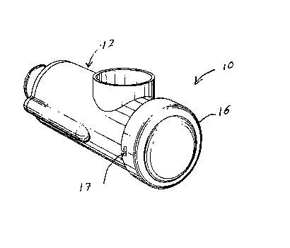
The device of the present invention may be incorporated as a novelty item
having various configurations. Thus, referring to Figure 1, there is
illustrated one
embodiment wherein the device is formed as a bat generally designated by
reference
numeral 10. Bat 10 has a handle 12 and spring 14 with the mechanism being
mounted
interiorly of the bat. A door 16 in the configuration of a baseball may
provide access
to the interior to place the nut in while the end of the bat opens as a door
18.
In the embodiment of Figure 2, the device is mounted interiorly of a chipmunk
configured character. In this case, the tail 24 functions as the handle while
an
opening 26 is provided to insert the nuts to be opened. Head portion 28 is
hingedly
connected to the body for removal of the nuts and shell.
In the embodiment of Figure 3, the device is configured as a soccer ball
generally designated by reference numeral 32. 'There is provided an opening 34
to the
interior of soccer ball 32 to place the nuts within the mechanism and a second
door 36
-4-

CA 02273118 1999-OS-27
for withdrawal of the cracked nut and segments. The base 38 functions as the
handle
of the device.
Referring to Figure 8, there is illustrated therein a tubular housing
generally
designated by reference numeral 70 and which includes a side wall 72
interiorly of
which there is an elongated passageway extending from a first end 74 to a
second
end 76. A pair of apertures 78 are formed within side wall 72 and located
proximate
ends 74 and 76. A locking prong 80 extends outwardly from side wall 72.
Designed
to fit over first end 74 is a first end cap 82 having an L-shaped recess 84
designed to
engage with locking pin 80 to retain end cap 82 in the desired position.
Located between ends 74 and 76 is an aperture 86 which defines a nut
receiving opening.
Also shown in Figure 8 is a first inner lining 87 along with an end cap 88 for
end 76 and associated component 90, each having apertures therein. Impacting
member 92 and a shaft 94 are designed to be connected to a handle 96.
The apparatus also includes a pair of pins 98. The nut cracking device is
designed to operate either with a pair of rubber bands 100 or a pair of
springs 102. A
pair of cover members 104 are provided for covering the rubber bands 100 and
102 as
they extend through apertures 78.
It will be understood that the above described embodiments are for purposes of
illustration only and that changes and modifications may be made thereto
without
departing from the spirit and scope of the invention.
-5-

Representative Drawing
A single figure which represents the drawing illustrating the invention.
Administrative Status

2024-08-01:As part of the Next Generation Patents (NGP) transition, the Canadian Patents Database (CPD) now contains a more detailed Event History, which replicates the Event Log of our new back-office solution.

Please note that "Inactive:" events refers to events no longer in use in our new back-office solution.

For a clearer understanding of the status of the application/patent presented on this page, the site Disclaimer , as well as the definitions for Patent , Event History , Maintenance Fee  and Payment History  should be consulted.

Event History

Description Date
Revocation of Agent Requirements Determined Compliant 2021-04-01
Application Not Reinstated by Deadline 2005-05-27
Time Limit for Reversal Expired 2005-05-27
Inactive: Abandon-RFE+Late fee unpaid-Correspondence sent 2004-05-27
Deemed Abandoned - Failure to Respond to Maintenance Fee Notice 2004-05-27
Application Published (Open to Public Inspection) 1999-11-27
Inactive: Cover page published 1999-11-26
Amendment Received - Voluntary Amendment 1999-08-27
Inactive: Correspondence - Formalities 1999-08-27
Inactive: First IPC assigned 1999-07-14
Filing Requirements Determined Compliant 1999-06-30
Inactive: Filing certificate - No RFE (English) 1999-06-30
Application Received - Regular National 1999-06-29

Abandonment History

Abandonment Date Reason Reinstatement Date
2004-05-27

Maintenance Fee

The last payment was received on 2003-05-23

Note : If the full payment has not been received on or before the date indicated, a further fee may be required which may be one of the following

  • the reinstatement fee;
  • the late payment fee; or
  • additional fee to reverse deemed expiry.

Please refer to the CIPO Patent Fees web page to see all current fee amounts.

Fee History

Fee Type Anniversary Year Due Date Paid Date
Application fee - small 1999-05-27
MF (application, 2nd anniv.) - small 02 2001-05-28 2001-05-24
MF (application, 3rd anniv.) - small 03 2002-05-27 2002-05-27
MF (application, 4th anniv.) - small 04 2003-05-27 2003-05-23
Owners on Record

Note: Records showing the ownership history in alphabetical order.

Current Owners on Record
JEAN BEAUCHEMIN
Past Owners on Record
None
Past Owners that do not appear in the "Owners on Record" listing will appear in other documentation within the application.
Documents

To view selected files, please enter reCAPTCHA code :


To view images, click a link in the Document Description column. To download the documents, select one or more checkboxes in the first column and then click the "Download Selected in PDF format (Zip Archive)" or the "Download Selected as Single PDF" button.

List of published and non-published patent-specific documents on the CPD .

If you have any difficulty accessing content, you can call the Client Service Centre at 1-866-997-1936 or send them an e-mail at CIPO Client Service Centre.


Document
Description 
Date
(yyyy-mm-dd) 
Number of pages   Size of Image (KB) 
Representative drawing 1999-11-16 1 9
Description 1999-05-27 5 196
Drawings 1999-05-27 4 92
Claims 1999-05-27 1 26
Cover Page 1999-11-16 1 31
Abstract 1999-08-27 1 18
Claims 1999-08-27 1 26
Drawings 1999-08-27 4 126
Filing Certificate (English) 1999-06-30 1 165
Reminder of maintenance fee due 2001-01-30 1 112
Reminder - Request for Examination 2004-01-28 1 113
Courtesy - Abandonment Letter (Request for Examination) 2004-08-05 1 166
Courtesy - Abandonment Letter (Maintenance Fee) 2004-07-22 1 175
Correspondence 1999-07-06 1 23
Correspondence 1999-08-27 8 218
Fees 2003-05-23 1 22
Fees 2002-05-27 1 25
Fees 2001-05-24 1 36