Note: Descriptions are shown in the official language in which they were submitted.
' CA 02273128 1999-OS-27
OPTICAL SYMBOL READING DEVICE
BACKGROUND OF TI-~E INVENTION
1. Field of the Invention
The present invention relates to a symbol reading
device, and particularly to an optical symbol reading
device for reading symbols on t:he front and back
surfaces of an article moved by, for example, a
conveyor.
2. Description of the Related Art
An article that is moved lby, for example, a
conveyor and that bears symbols to be read, movement
caused by the conveyor brings t:he front surface of the
article toward the symbol reading device and then moves
the back surface away from the symbol reading device.
In other words, when reading symbols on the front or
back surface of an article, the input of the image data
of the symbols must be carried out while the reading
distance, which is the distances between the reading
device and the symbols, is in a constantly changing
state.
Typical methods of receiving optical image data
include the use of a camera such as an image pickup tube
or CCD, or directing a laser beam scan light onto the
CA 02273128 1999-OS-27
surface to which symbols are applied and detecting the
reflected light.
Fig. 1 shows a symbol reading device of the prior
art that reads bar code labels by scanning by a laser
beam.
In the prior-art symbol reading device of Fig. 1,
article detector (light projeci~ion) 26a and article
detector (light reception) 26b first detect that an
article bearing a bar code to be read has entered the
read zone, following which image data input unit 10,
which constitutes image data input section 1, directs a
laser beam scanning light upon the surface of the bar
code label, a photo-sensor dets~cts the light of the
laser beam scanning light that is reflected from the
surface of the bar code label, an electric signal
converter converts the detection lights to electric
signals and these are interprei~ed by interpreter 2, and
the interpretation results are then outputted by way of
interpretation result output sE~ction 3 to an external
device. Image data input section 1 that uses a camera is
made up by a camera that uses an image pickup tube or
CCD.
As can be understood from focusing a camera, a
clear image free of blurring can be obtained in image
data input by camera of the prior art by focusing such
that the reading distance, which is the distance between
2
CA 02273128 1999-OS-27
the camera and the symbol, i.e., the article to be read,
is equal to the focal length of the camera lens.
In other words, clear images that are free from
blurring cannot be obtained whs~n reading symbols on the
front and back surfaces becauss~ the above-described
reading distance is constantly changing as described
above.
Similarly, regarding the :method of the prior art in
which a laser beam scan light _~s irradiated, it is
common knowledge that the beam diameter of the laser
beam scanning light such as oui~putted from the image
data input unit is not uniform but rather, first
converges with increasing distance from the image data
input unit and then diverges. At the waist position at
which the laser beam converges to its narrowest
diameter, i.e., at the focus point, resolution is high
and a clear image free of blurring can be obtained, but
at positions other than the focus point, the laser beam
broadens, resolution falls, an<i as with the above-
described camera, blurring occurs and a clear image
cannot be obtained.
In other words, when input of image data is carried
out at points other than the focus point in a symbol
reading device in which reading is realized by
irradiating a laser beam upon a bar code label and then
reading the reflected light, the laser beam diameter is
3
CA 02273128 1999-OS-27
broad and resolution is low. As a result, the bar
widths that make up a bar code cannot be accurately
detected and the reading performance of the symbol
reading device suffers. In image data input by means of
a camera as well, the image goes out of focus, clear
image data cannot be obtained, and reading performance
drops.
For these reasons, large symbols have been used
with symbol reading devices of the prior art that read
symbols on front and back surfaces, thereby reducing the
effect of the above-described blurring.
With large symbols, symbol data are not lost
despite blurring. Larger symbols, however, require
larger labels or paper for printing, and therefore
entail the disadvantage of increased operation costs.
A further disadvantage is that larger labels cannot
be applied to small articles.
SUMMARY OF THE INVENTION
It is an object of the present invention to
provide a high-performance optical symbol reading device
that is capable of always matching the focus point to
the front or back surface of an article when reading the
front surface or back surface of an article for which
the reading distance is in constant change.
4
CA 02273128 2002-04-30
74570-72
In accordance with the present invention, there is
provided an optical symbol reading device comprising: an
image data input section that is provided with an image data
input unit for receiving image data from a visual image
selected from the group consisting of bar code labels,
characters, symbols, and image data, on an article that is
moved by a conveyer, and an image data input focus point
modifier; an article detector for detecting that said
article has entered a read zone; an interpreter for
converting to numbers or characters, electric signals
generated by said image data input section in response to
said image data; an interpretation result output section for
outputting the interpretation results of said interpreter to
an external device; a front surface and back surface
position detector for detecting a position on said conveyer
of a front surface and a back surface of an article that is
moved by said conveyer; and an image data input focus point
control section for outputting data from said front surface
and back surface position detector to said image data input
focus point modifier.
In addition, the front surface/back surface
position detector is provided with means that is provided
with a light projection position detector and a light
reception position detector made up of a plurality of
transmissive multiple optical axis sensors, for
5
CA 02273128 1999-OS-27
finding the position of the front surface or back
surface of an article by detecting which transmissive
multiple optical axis sensors of the plurality of
transmissive multiple optical axis sensors of the light
projection position detector are being shielded by the
article.
In addition, the front surface/back surface
position detector is provided with means that includes a
rotary encoder that is attached to the conveyor, for
finding the position of the front surface or back
surface of the article by counting pulses from the
rotary encoder and measuring th.e distance of movement of
the conveyor.
In addition, the image dai~a input focus point
control section may also include means for converting
the front surface/back surface position data of the
article that are received from the front surface/back
surface position detector to a reading distance, which
is the distance between the image data input unit and
the front surface or back surface of the article, and
outputting the reading distance as focus point data to
the image data input focus point modifier.
In addition, the image dai~a input focus point
modifier may include means for matching the focus point
to the front surface or back surface of an article that
is constantly moving over time by setting the focus
6
CA 02273128 1999-OS-27
point to a position designated by focus point data that
are received from the image data input focus point
control section.
Further, means may be included for reading two
surfaces, i.e., the side surface/back surface or side
surface/front surface of an article that is moved by a
conveyor, by fixing the focus on the position of the
side surface and reading the side surface when receiving
a bar code label, characters, symbols, or image data on
a side surface of the article from the image data input
unit.
In other words, this invention provides an image
data input focus point control section that outputs
position data of an article that are received from the
front surface/back surface position detector to an image
data input focus point modifier for the purpose of
obtaining clear image data of, for example, symbols
applied to the front or back surface of an article that
is being moved by, for example, a conveyor and for which
the reading distance is constantly changing, thereby
enabling matching of the focus point of a camera or
waist point of a laser beam for image data input to the
front or back surface of the article and realizing the
input of clear image data.
The above and other objects, features, and
advantages of the present invention will become apparent
7
CA 02273128 1999-OS-27
from the following description based on the accompanying
drawings which illustrate an example of a preferred
embodiment of the present invention.
BRIEF DESCRIPTION OF THE DRAWINGS
Fig. 1 is a block diagram showing reading of
symbols on a front surface/back: surface by a symbol
reading device of the prior art. which reads a bar code
label by scanning a laser beam according to techniques
of the prior art;
Fig. 2 is a block diagram showing an optical symbol
reading device according to an embodiment of the present
invention;
Fig. 3 shows the arrangems~nt of the optical symbol
reading device of the embodiment of the invention and
the position of the conveyed article; and
Fig. 4 again shows the arrangement of the optical
symbol reading device of the embodiment of the invention
and the position of the conveyE~d article.
DETAILED DESCRIPTION OF THE PREFERRED EMBODIMENTS
An embodiment of the invention is next described
with reference to the accompanying figures. Fig. 2 is a
block diagram showing the optical symbol reading device
according to the embodiment of the invention.
8
CA 02273128 1999-OS-27
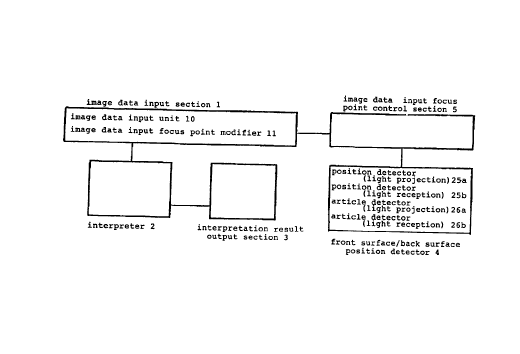
The symbol reading device according to the
invention shown in Fig. 2 is made up of: image data
input section 1 which is composed of image data input
unit 10 and image data input focus point modifier 11;
interpreter 2, interpretation result output section 3,
front surface/back surface position detector 4, and
image data input focus point control section 5.
Operation of the symbol rE~ading device according to
the invention is next explained) using Fig. 2, Fig. 3,
and Fig. 4. Figs. 3 and 4 show views taken from
directly above the conveyor of article 27 being conveyed
by conveyor 22 toward the left in Fig. 3 and Fig. 4 as
shown by conveyance direction 28. Front surface symbol
reading device 20 reads symbols. by scanning front
surface 23 of article 27 in an up-down direction by
means of scanning beam 30 composed of a laser beam and
receiving the light reflected from the symbols, such as
a bar code label, present on front surface 23. In the
same way as front surface symbol reading device 20, back
surface symbol reading device f1 reads symbols by
scanning back surface 24 in an up-down direction by
means of scanning beam 31 composed of a laser beam and
receiving the light reflected from the symbols, such as
a bar code label, present on back surface 24.
Article 27 is first conveyed by conveyor 22 in the
direction of conveyance direction 28, and the back end
9
CA 02273128 1999-OS-27
of conveyed article 27 is detected by article detectors
26a and 26b when the article reaches the position shown
in Fig. 3. Article detectors 26a and 26b typically
employ a transmissive sensor or a reflective sensor.
Here, the back end of conveyed article 27 is the
back surface of conveyed article 27. Scanning beam 31
must be directed onto back surface 24 in order to read
symbols present on the back surface of article 27, and
the position of article 27 shown in Fig. 3 is the
starting point of this irradiation. The position of
article 27 shown in Fig. 4 is the ending point of this
irradiation. This ending point is related to the width
of article 27, and a particular set value is therefore
established and scanning ends when the back end of
article 27 exceeds this set value.
Back surface symbol reading device 21 begins
reading the symbols on back surface 24 of article 27
from the position of article 27 shown in Fig. 3 and
completes the scanning of back surface 24 at the
position shown in Fig. 4.
Here, article 27 is moved by conveyor 22, and the
movement of back surface 24 away from back surface
symbol reading device 21 causes a change in the distance
between back surface symbol reading device 21 and back
surface 24, i.e., the reading distance, and this change
can be seen in the change of the length of scanning beam
CA 02273128 1999-OS-27
31 in Fig. 3 and Fig. 4. Similarly, it can be seen from
Fig. 3 and Fig. 4 that the approach of front surface 23
to front surface symbol readincT device 20 brings about
change in the distance between front surface symbol
reading device 20 and front surface 23, i.e., the
reading distance.
To obtain clear image data of symbols such as bar
code present on back surface 29E, the focus point of the
symbol reading device must be constantly matched to the
reading distance, which change: constantly with the
movement of article 27 as described hereinabove.
The above-described focus point is the focus point
of the scanning beam realized by a laser beam outputted
by image data input unit 10 or the camera incorporated
in image data input unit 10.
To realize this matching, front surface/back
position detector 4 of article 27 first detects the back
end of article 27 by means of article detectors 26a and
26b and then outputs this detection as a back end
detection signal to image data input focus point control
section 5.
Image data input focus point modifier 11 receives
the focus point data from image data input focus point
control section S and has the function of setting to any
distance the focus point of a camera or of a scanning
11
CA 02273128 1999-OS-27
beam realized by a laser beam outputted by image data
input unit 10.
Accordingly, upon receiving the back end detection
signal, image data input focus point control section 5
outputs the focus point information, which corresponds
to the length of the broken line of scanning beam 31, to
image data input focus point modifier 11, which is to
set the focus point at this time point to the length of
the broken line of scanning beam 31 as shown in Fig. 3.
This operation enables matching of the focus point to
back surface 24 of article 27 shown in Fig. 3.
Article 27 then moves in i~he direction of
conveyance direction 28 and they reading distance
accordingly changes. It can here be seen from Fig. 3
that this reading distance is determined by the position
of article 27 on conveyor 22. Figs. 3 and 4 show a
method in which the detection of the position of article
27 on conveyor 22 is realized by position detector
(light projection) 25a and position detector (light
reception) 25b made up of a plurality of transmissive
multiple optical axis sensors. This is a method by
which the back end of article f7 is directly found
depending on where the plurality of sensors of position
detector (light projection) 25a are shielded by article
27. Front surface/back surfaced position detector 4 then
outputs the back end position data of article 27
12
CA 02273128 1999-OS-27
outputted from position detector (light reception) 25b
to image data input focus point: control section 5.
Image data input focus point control section 5 next
converts the back end position data to the reading
distance and outputs the result: as focus point data to
image data input focus point modifier 11. Image data
input focus point modifier 11 c:an then match the focus
point to back surface 24 of constantly moving article 27
by setting the focus point to t:he position set by the
focus point data. Clear image data input can therefore
be obtained and a high-performance symbol reading device
can be realized.
Reading of front surface 23 is equivalent to that
for back surface 24 and explanation is therefore here
omitted.
Although transmissive multiple optical axis sensors
were employed for position detectors 25a and 25b in
Figs. 3 and 4, a method may also be used by which the
position of an article is detected by attaching a rotary
encoder to the conveyor and then measuring the distance
of movement of the conveyor by counting pulses from the
rotary encoder. Alternatively, if the conveyance speed
of the conveyor is known, the position of the back end
of an article can also be obtained by calculating the
elapsed time following detection of the back end of the
article by article detectors 26a and 26b.
13
CA 02273128 1999-OS-27
During the time interval from detection of front
surface 23 of article 27 by article detectors 26a and
26b to detection of back surface 24, scanning beam 31
scans side surface 25, and since the reading distance is
fixed at this stage, reading of side surface 25 can be
realized with the focus fixed to the position of side
surface 25. In this way, reading of two sides, i.e.,
the side surface/back surface or the front/side surface,
can be realized by a single symbol reading device.
In addition, this invention is effective not only
in a linear CCD or line scanning laser scan-type symbol
reading device in which the track of the scanning beam
is a straight line, but in a symbol reading device that
takes in and reads a two-dimensional image.
The invention as described hereinabove enables
matching of the focus point to the front surface/back
surface of an article even in the case of reading the
front surface/back surface of an article for which
reading distance is changing over time, thereby enabling
clear image data to be obtained and providing a high-
performance symbol reading device for symbols present on
the front surface/back surface of an article.
While a preferred embodiment of the present
invention has been described using specific terms, such
description is for illustrative purposes only, and it is
to be understood that changes and variations may be made
14
CA 02273128 1999-OS-27
without departing from the spirit or scope of the
following claims.