Note: Descriptions are shown in the official language in which they were submitted.
CA 02273229 1999-OS-31
1 ; -:~ l~:( ~_;
59-153-3 ,~~
FEMUR COMPONENT OF A HIP-JOINT ENDOPROSTHESIS.
The invention relates to a femur component of a hip-joint endoprosthesis
defined
in the preamble of claim 1.
s Such femur components already are known from the state of the art, however
they
incur various drawbacks.
As regards uncemented femur prostheses for hip-joint replacement, the primary
stabilization of the femur shaft is implemented by frictionally and
geometrically locking
onto the enclosing bone. The femur shaft shall be configured in such manner
that loading
io it will entail its being wedged into the bony support. In particular during
the first loading
phase wherein some seating shifts of the femur shaft are likely, a
corresponding
configuration must assure reliable primary affixation. In the event of a
seating shift, new
stabilization must be assured by corresponding reconfiguration. In the absence
of
adequate primary stability, loading will entail repeated shifts at the
boundary surface
~s between femur shaft and bone, preventing reliable implant bodily
incorporation. On the
other hand, if the primary anchoring is reliable, the implant can be enclosed
by the bone
tissue during the healing process and offer good long-term prospects.
Preferably the primary affixation shall be in the upper portion of the
prosthesis shaft
enclosed by the spongy bone. A large support surface can be achieved in the
big bone
2o volume present therein. Seen biomechanically/clinically, it has been
advantageous to
apply the force through this region.
Illustratively a femur shaft is on the market wherein the proximal shaft
portion
intended to be anchored in the spongy bone structure continuously tapers
sonically in the
lateral-to-mesial direction in order to secure renewed, automatic clamping in
the event the
zs bone would yield in the mesial direction. The region of the trochanter
major with the
anchoring space however does not have a cross-sectionally triangular or
trapezoidal shape,
rather an oval one. Accordingly this known femur shaft suffers from the
drawback that
CA 02273229 1999-OS-31
2 59-153-3
the laterally much enlarged proximal shaft portion may crack the bone. In
addition this
known femur shaft comprises solid ribs which when displacing bone volume will
raise the
pressure and may further contribute to the cracking effect.
A longitudinal section of the proximal femur with inserted femur shaft shows
that
s the spongy substance is not sharply delimited to the trochanter region but
instead partly
continues as far as the zone of the diaphyseal bone tube. However as much as
possible
of this bone structure should be used to transmit the load. But the ribs
located in one
position of the known femur shaft do not optimally meet this requirement
because of the
little differentiated configuration. The point of contact and the elongation
of the ribs at the
io shaft should be designed in such manner that as much as possible of the
spongy volume
of the proximal femur is used for anchoring.
In this respect, the object of the invention is palliation. The invention
addresses
the problem of creating a femur component of a hip-joint endoprosthesis
optimally
corresponding to the spongy architecture in the proximal femur part and
entailing
is cementless, primary shaft anchoring in the femur in the most stable
possible manner to
secure thereby good likelihood of bone healing.
The invention solves this problem by a femur component defined by the features
of claim 1.
The double-wedge or ellipsoidal shape of the proximal shaft segment offers the
zo advantage that the prostheses shaft can wedge itself both laterally and
mesially in the
event of a seating shift. The oval envelope curve of the ribs matching the
cross-section
of the proximal femur minimizes the danger of cracking the proximal femur due
to direct
pressure on the hard cortical bone.
In a preferred further development of the invention, wherein the ribs are
cross-
2s sectionally triangular, these ribs easily penetrate the spongy bone volume
and as a result
the pressure is reduced during the insertion procedure. Because preferably the
triangular
CA 02273229 1999-OS-31
3 59-153-3
ribs run conically, additional wedging is achieved that is lacking in
rectangular ribs such
as are used in the state of the art.
The straigthness of the shaft together with the increasing height in the
proximal
direction of the ribs running in the direction of the shaft axis allows secure
positioning and
s the femur shaft and knocking it into place with guidance by the self-cutting
ribs. If on the
other hand the ribs are partly or all mounted at an angle to the shaft axis,
no seat
enclosing the ribs can be realized when installing the femur shaft. Because
the rib
projection varies along the shaft, the stress on the spongy volume is more
homogeneous
than in known shafts with ribs beginning at a given height which then
continuously
io increases.
Another preferred development consists in that the combs of the longitudinal
ribs
subtend an angle'/zb of at least 1°, preferably at least 2° with
the plane of symmetry. The
individual combs of the longitudinal ribs subtend different angles '/zb in the
range of 3 to
8° with the plane of symmetry, preferably the longitudinal ribs
situated closer to the lateral
~s and the mesial side subtending a larger angle '/zb than those in-between.
Such a rib
geometry functionally stimulates the enclosing bone, whereas such a stimulus
is not
achieved with the dull rib shape of the state of the art. This functional
stimulus causes
bone regeneration in the stressed zone with ensuing compaction and hence bone
healing.
The blood supply to the regenerated bone can optimally form in the troughs of
this rib
2o structure.
Appropriately the anterior and posterior surfaces form a wedge tapering toward
the
distal segment, the central plane being the plane of symmetry, the angle ~ of
the wedge
being in the range of 0.5 to 3.0°, preferably within 1.0 and
2.0°. On account of this
geometry, the wedging effect is continued also along the upper shaft zone. In
case sub-
zs sequent intervention is due on a solidly integrated shaft, the shaft is
more easily knocked
free if its geometry is conical in all directions, that is also proximally in
the intra-rib zone,
than if the geometry were other than conical.
CA 02273229 1999-OS-31
4 59-153-3
Seen in a section orthogonal to the plane of symmetry, the envelope curve of
the
combs of the longitudinal ribs is approximately in the form of a kite
quadrilateral of which
the sides may approximately represent straight lines or arcs of circle or
elliptical segments.
Relative to the mesial side, the kite quadrilateral should subtend an inside
angle a
s larger than 10, and preferably larger than 12°. In addition the
inside angle a should be
less than 22, preferably less than 20°.
Toward the lateral side, the kite quadrilateral should subtend an inside angle
~
larger than 8, preferably larger than 9°. Moreover the inside angle ~3
should be less than
45, preferably less than 40°.
io Appropriately the longitudinal-rib combs are sharp and seen in a section
orthogonal
to the plane of symmetry are preferably triangular. Illustratively the
longitudinal ribs may
assume the shape of three-sided pyramids of which the vertices point distally.
The
longitudinal-rib combs however may also be rounded and, seen in a section
orthogonal to
the plane of symmetry, preferably are semi-circular. On the other hand
uniformly thick
is longitudinal ribs of rectangular cross-section are to be avoided.
Preferably in continuous manner, the width of the longitudinal ribs
appropriately
decreases from the proximal to the distal sides. This design also applies to
the height of
the longitudinal ribs which preferably continuously shall decrease in the
proximal-to-distal
direction.
2o Surprisingly especially good clinical results were observed when at least
one of the
longitudinal ribs runs as far as the distal half of the shaft because making
possible thereby
increased primary stability and because bone regeneration or bone
transformation
propagates proximally from this anchoring zone in the form of osteo-
conduction.
Further advantages may be achieved using embodiments wherein the shaft is
2s without collar and assumes a substantially rectangular cross-section as
seen in a section
orthogonal to the plane of symmetry.
CA 02273229 1999-OS-31
59-153-3
The invention and its further developments are elucidated below in relation to
several embodiments shown in the partly schematic Figures.
Fig. 1 is an elevation of the femur component of the invention seen from the
anterior side and with two cross-sectional contours,
s Fig. 2 is an elevation of the femur component of Fig. 2 seen from the
lateral side,
Fig. 3 is a section of the femur component of Fig. 1 along line III-III and
Fig. 4 is a section similar to that of Fig. 3 with a modified envelope curve
of the
longitudinal-rib combs.
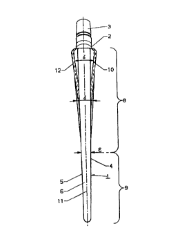
The femur component of a hip-joint endoprosthesis shown in Figs. 1 through 3
io essentially comprises a shaft 1 without collar with a distal segment 9 and
a proximal
segment 8 adjoined by a neck 2 with a stub 3 to receive a hinge head, or by a
hinge head
firmly joining the neck 2. The shaft 1 comprises an anterior surface 4, a
posterior surface
5, a lateral side 6, a mesial side 7 and a plane of symmetry 11 identical with
the plane of
Fig. 1. Shown in a section orthogonal to the plane of symmetry 11, the shaft
is of a
is substantially rectangular cross-section 14.
Longitudinal ribs 10 are present on the anterior and posterior surfaces 4 and
5 resp.
in the proximal segment 8 of the shaft 1 and run from the proximal side to the
distal side.
Depending on their positions, the combs 12 of the longitudinal ribs 10 subtend
and an
angle '/2b of 3 to 8 ° with the plane of symmetry il. The longitudinal
ribs 10 near the
zo lateral side 6 and mesial side 7 subtend a larger angle'/zb than the
longitudinal ribs 10 in-
between. Moreover the individual longitudinal ribs 10 are of different
lengths, preferably
those located toward the lateral side 6 and the mesial side 7 being shorter
than those in
between. The line 17 connecting the ends 18 of the longitudinal ribs 10
merging into the
anterior and posterior surfaces 4, 5 do not lie on a straight line but instead
on a parabolic
zs or ellipsoidal curve.
CA 02273229 1999-OS-31
59-153-3
The envelope curves of the combs 12 of the longitudinal ribs 10 subtend a
double-
wedge or an ellipsoidal body tapering both in the direction of the lateral
side 6 and in the
direction of the mesial sides 6, 7.
Furthermore the anterior surface 4 together with the posterior surface 5 forms
a
s wedge 4,5 tapering toward the distal segment 9, the plane of symmetry 11
being the
center plane, the wedge angle ~ of the wedge 4, 5 being 0.5°.
As shown in Fig. 3, when seen in a section orthogonal to the plane of symmetry
11,
the envelope curve of the combs 12 of the longitudinal ribs 10 form a kite
quadrilateral 13,
the quadrilateral's short sides pointing laterally and its long sides pointing
mesially.
o The inside angle a of the kite quadrilateral 13 is 12 to 20° toward
the mesial side
7 and its inside angle (3 toward the lateral side 6 is from 9 to 44°.
The combs 12 of the longitudinal ribs 10 are sharp and when seen in a section
orthogonal to the plane of symmetry 11 their contour is triangular. The width
and height
of the longitudinal ribs 10 decrease continuously in the proximal-to-distal
direction.
is Accordingly the longitudinal ribs 12 form three-sided pyramids, the vertex
of the pyramid
pointing distally. Therefore the troughs between the individual longitudinal
ribs 10 narrow
from the distal segment 9 to the proximal segment 8.
As shown in Fig. 1, one of the longitudinal ribs 12, namely the center one,
runs as
far as the distal half of the shaft 1 and thereby enhances the primary
stability of the
2o implanted shaft.
The envelope curve of the combs 12 of the longitudinal ribs 10 shown as a kite
quadrilateral 13 in Fig. 3 also may comprise slightly outward bulging, for
instance arcuate
envelope curves 15, as shown in Fig. 4. In this embodiment the angles o and Q
relate to
the inside angles of the kite quadrilateral formed by the tangents 16 to the
convex
2s envelope curves.