Note: Descriptions are shown in the official language in which they were submitted.
CA 02273520 1999-07-29
1
TITLE: SHAPED ICE ARTICLE AND ARTICLE FOR MAKING SAME
BACKGROUND OF THE INVENTION
This application is a Continuation-In-Part application of Serial No.
09/089,283, filed June 2, 1998.
This invention pertains to methods and apparatuses for chilling beverages, and
more specifically to methods and apparatuses for freezing substances into
useful forms such
that the freezable substances, once frozen, have an elongated, narrow form
such that they are
insertable into a beverage container, beverage can, juice can, water bottle,
sports bottle or the
like and can more effectively cool the entire depth of the beverage.
DESCRIPTION OF THE RELATED ART
Basic "cube-shaped" ice "cubes" and ice cube trays are known in the prior art.
Typically, ice cube trays are designed to produce ice cubes having a cubic or
rectangular
form. The prior art also teaches ice cube trays which produce ice cubes having
a variety of
forms. For example, in U.S. 4,417,716 an ice tray is disclosed which forms
completely
enclosed chambers of different shaped ice. Further, in Des. 287,856 another
shaped ice cube
tray is disclosed. Other designs are disclosed in U.S. Des. Pat. Nos.
D244,275; D292,802;
and D318,281.
Notwithstanding the fact that the prior art teaches both ice cubes having a
variety of forms and the ice cube trays for making these ice cubes, the prior
art does not teach
a frozen substance or a method of freezing a substance such that the freezable
substance, once
frozen, has an elongated form such that the frozen substance is insertable
into a beverage
container, beverage can, juice can, water bottle, sports bottle or the like
and resultingly more
effectively cools the entire depth of the beverage.
For example, a conventional beverage can has a depth of about 5.0 inches ( 127
mm) and has an opening with a width of about 0.75 inches (19.05 mm). Beverage
containers
such as water, soda or beverage bottles have various depths ranging from about
11.0 inches
(279.4 mm) for a typical polyester two liter bottle to about 6.0 inches (
152.4 mm) for a
CA 02273520 1999-07-29
2
typical bottled water bottle. These containers also have openings of various
widths. Neither
the conventional cubic or rectangular ice cubes, nor the various forms of ice
cubes that the
prior art teaches, are insertable within these containers because of the
narrowness of the
containers' openings. Consequently these beverages can not be easily cooled in
their
containers by the addition of ice cubes or other frozen substances. The only
way to cool
these beverages while they are in their containers is to place them into a
cool environment
such as a refrigerator, freezer, ice box, ice bucket, cooler, tub of ice, or
the like. However,
the introduction of a beverage container into a very cold environment can lead
to a messy
result as the beverage container may rupture as the freezable substance within
the container
expands during freezing.
Furthermore, when a straw is used to consume a beverage, the use of
conventional ice cubes in the beverage does not achieve the advantages offered
by the current
invention. It is common knowledge that when ice is added to a beverage, the
ice floats.
Consequently, the upper, rather than the lower, portion of the beverage is
cooled. When a
straw is used to consume the beverage, the non-cooled lower portion of the
beverage is
sucked up through the straw and introduced into the consumer's mouth rather
than the cooled
upper portion of the beverage wherein the ice cubes reside. This is
dissatisfying and contrary
to the motives behind adding ice cubes to beverage containers; namely,
consuming a cool
beverage. The current invention solves this problem. The elongated form of the
current
invention assures that the frozen substance is narrow and insertable into a
beverage container,
beverage can, juice can, water bottle, sports bottle or the like and that the
lower portion of
the beverage, from which the beverage is consumed when the consumer uses a
straw, is
cooled.
~ITMMARY OF THE INVENTION
According to one aspect of the invention, a body is provided which has at
least
one elongated cavity within it. The cavity has a top, a bottom and sidewalk
between the top
and bottom. The freezable substance is placed into the cavity through the top
or bottom. The
top and/or bottom have a maximum width, Wm, which is less than or equal to
0.875 inches
CA 02273520 1999-07-29
3
(22.23 mm).
According to another aspect of the invention, a body is provided which has
at least one elongated cavity within it. The cavity has a top, a bottom and
sidewalls between
the top and bottom. The freezable substance is placed into the cavity through
the top or
bottom. The top and/or bottom have a maximum width, Wm, which is less than or
equal to
1.1875 inches (30.1625 mm).
According to another aspect of the invention the top and/or bottom have a
maximum width, Wm, which is less than or equal to 0.625 inches ( 15.875 mm).
According to another aspect of the invention the cavity has a depth, X. The
depth X of the cavity is measured from the top of the cavity to the bottom of
the cavity, or
vice versa. The depth X is greater than or equal to 1.5 inches (38.1 mm).
According to another aspect of the invention the top may be circular, having
a diameter Dt. The bottom may also be circular, having a diameter Db, where Db
is less than
or equal to Dt.
According to another aspect of the invention the width of the cavity is less
than or equal to 0.875 inches (22.23 mm) at any point along its depth.
According to another aspect of the invention the width of the cavity is less
than or equal to 0.625 inches ( 15: 875 mm) at any point along its depth.
According to another aspect of the invention the width of the cavity at any
point along its depth is less than or equal to the width of the top of the
cavity. Additionally,
the width of the cavity at any point along its depth is greater than or equal
to the width of the
bottom of the cavity.
According to another aspect of the invention the article has a sealing means
for selectively sealing the top or bottom so that the freezable substance
cannot spill out of the
cavity prior to becoming frozen. The means for sealing the opening can take
the
configuration of a lid, "zip-loc" mechanism, screw-in mechanism, frictionally
fastening means
or any other like means which would prevent spillage of the freezable
substance prior to its
freezing.
CA 02273520 1999-07-29
4
According to another aspect of the invention, a body is provided which has
at least one elongated cavity within it. The cavity has a top and bottom, and
sidewalls
between the top and bottom. The freezable substance is placed into the cavity
through either
the top or bottom. The top and/or bottom have a maximum width, Wm, which is
less than
or equal to 0.875 inches (22.23 mm). The body also has sealing means for
selectively sealing
the top and/or the bottom, so that the freezable substance is not spillable
from the cavity prior
to the freezable substance becoming frozen.
According to yet another aspect of the invention, a tray for freezing water to
form ice cubes is disclosed using a plurality of body's having one cavity
within said body,
cavity having an top and bottom, and side walls therebetween. The tray also
comprises
sealing means for the body's to selectively sealing the top and/or the bottom,
so that the
freezable substance is not spillable from the cavity prior to the freezable
substance becoming
frozen. Further, the tray has attachment means to attach the plurality of
body's to one
whereby the plurality of body's are integral and form the tray.
Still other benefits and advantages of the invention will become apparent to
those skilled in the art to which it pertains upon a reading and understanding
of the following
detailed specification.
BRIEF DESCRIPTION OF THE DRAWINGS
The invention may take physical form in certain parts and arrangement of
parts, a preferred embodiment of which will be described in detail in this
specification and
illustrated in the accompanying drawings which form a part hereof and wherein:
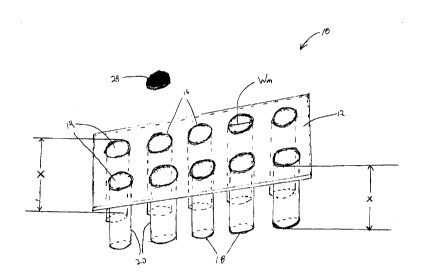
FIGURE 1 is a perspective view of one embodiment of the invention having
more than one cavity;
FIGURE 2 is a top view of one embodiment of the invention having more than
one cavity;
FIGURE 3 is a side view of one embodiment of the invention having more
than one cavity;
CA 02273520 1999-07-29
S
FIGURE 4 is a side view of a cavity;
FIGURE S is a side view of an ice structure (or ice cube) formed from a
cavity;
FIGURE 6 is a side view, in partial cross-section, of an associated beverage
container with the inventive chilling article installed inside, and,
FIGURE 7 is a perspective view of a tray for freezing water to form ice cubes.
DESCRIPTION OF THE PREFERRED EMBODIMENT
Referring now to the drawings wherein the showings are for purposes of
illustrating a preferred embodiment of the invention only and not for purposes
of limiting the
same, FIGS. 1, 2 and 3 show the preferred embodiment of the invention.
Throughout this
specification, the term "ice cube" and "ice cube tray" will be used for
convenience of the
reader, even though the shape and form of the ice formed by the inventive
structure may- not
be cubic. In addition, while the invention will be referred to in the context
of freezing water
to form ice, any freezable substance is within the scope of the invention.
In the preferred embodiment, a body 12 of an article 10 contains multiple
cavities 14. Each cavity 14 has an open top 16 and open bottom 18 and side
walls 20
between the top 16 and bottom 18. The top 16 and/or bottom 18 of each cavity
14 has a
maximum width Wm of less than or equal to 0.625 inches ( 15.875 mm). Each
cavity 14 has
a depth X of greater than or equal to 1.5 inches (38.1 mm). The depth X is
measured from
the top 16 to the bottom 18, as shown in the Figure 1.
The maximum width Wm is important, as the primary goal of the invention is
to cool drinks within their respective containers. Because most of the drink
containers
presently have interior diameters less than 0.625 inches (15.875 mm), the
present invention
provides a way to effectively cool the beverage within its original container.
Further, because
the ice cube is now "narrow", and because cooling is a function of surface
area, the length of
the ice cube is necessarily lengthened in order to provide the requisite level
of cooling.
Therefore, in an ice cube formed by the inventive article, the depth X is
greater than a
conventional ice cube. Also because of the greater surface area ai~orded, the
preferred form
CA 02273520 1999-07-29
6
of the cavity is one that will provide a generally cylindrical shaped ice
cube. However, it is
within the scope of this invention to have ice cubes having shapes not
generally cylindrical.
FIG. 4 shows a side view of a cavity 14 wherein the freezable substance is
formed as it freezes. The top 16 may be circular having a diameter Dt. The
bottom 18 may
be circular having a diameter Db.
In addition to the foregoing, FIG. 1 also shows another embodiment wherein
a sealing means 24 is used to prevent the freezable substance from spilling
out of the cavity
14 prior to freezing. The sealing means 24 may comprise any type of sealing
that does not
allow the freezable substance from exiting the cavity 14 prior to its
freezing. Typically, the
sealing means comprises a cap 25 that may be attached to the body 12. The
sealing means
may also be a screw-type of arrangement whereby the sealing means comprises a
threaded
attachment to either the top 16 or bottom 18 of the body 12.
In addition to the foregoing another embodiment is contemplated wherein the
maximum width Wm of the top 16 and/or bottom 18 is less than or equal to 0.625
inches
(15.875 mm).
In addition to the foregoing another embodiment is contemplated wherein the
cavity has a width less than or equal to 0.875 inches (22.23 mm) at any point
along its depth,
which is typically less than soda bottles. However, for drinks typically
having a wider cavity
or "mouth", the width is less than or equal to 1.1875 inches (30.1625 mm).
These containers
are typically found on wider "mouth" sport and/or soda bottles.
In addition to the foregoing another embodiment is contemplated wherein the
cavity has a width less than or equal to 0.625 inches (15.875 mm) at any point
along its depth.
In addition to the foregoing, with reference to FIG. 5, another embodiment
is illustrated wherein the diameter of the bottom Db is less than or equal to
the diameter of
the top Dt.
In addition to the foregoing, with continued reference to FIG. 5, another
embodiment is contemplated wherein the width of the cavity at any point along
its depth is
less than or equal to the width of the top and greater than or equal to the
width of the bottom.
Also shown in FIGS. 4 and 5 is another preferred embodiment in which the
bottom 18 has a
CA 02273520 1999-07-29
7
rounded, somewhat spherical surface 80. It is believed the rounded surface 80
will ease the
removal of the ice cube or ice structure 88.
With reference to FIGURE 6, the method of chilling a beverage within its
original container will now be described. In a typical beverage container 90,
the lid 92 is
removed, typically by unscrewing the lid 92 from the container 90 via threads
94, depending
upon the beverage used. The frozen ice structure 88 is then inserted into the
container 90 so
that the longitudinal centerline of the structure 88 is coaxial with the
longitudinal centerline
of the beverage container 90. The entire depth of the beverage 96 becomes
cooled and chilled
by the article 88.
With reference to Figure 7, a tray 50 for freezing water to form the ice cubes
mentioned hereinabove is shown. The tray comprises a plurality of body's 12
having one
cavity 14 within the body 12. The tray also has the sealing means for
selectively sealing the
top and/or the bottom, so that the freezable substance is not spillable from
the cavity 14 prior
to the freezable substance becoming frozen. The tray 50 also has attachment
means 51 to
attach the plurality of body's 12 to one another thus making the body's 12 are
integral with
one another and forming the tray 50.
The preferred embodiments have been described. It will be apparent to those
skilled in the art that the above methods may incorporate changes and
modifications without
departing from the general scope of this invention. It is intended to include
all such
modifications and alterations in so far as they come within the scope of the
appended claims
or the equivalents thereof.
Having thus described the invention, it is now claimed: