Note: Descriptions are shown in the official language in which they were submitted.
CA 02273550 1999-06-02
-20633
- 1 -
PROCESS INTEGRATING A SOLID OXIDE FUEL CELL
AND AN ION TRANSPORT REACTOR
FIELD OF THE INVENTION
This invention relates to a process for the
co-generation of power and at least one product gas.
More particularly, the process integrates a solid oxide
fuel cell and an ion transport reactor.
BACKGROUND OF THE INVENTION
Electrical power is traditionally generated by a
thermodynamic process. Heat, for example, may be
generated by burning oil in a boiler to superheat
pressurized water. The superheated water is expanded
into pressurized steam that mechanically rotates a
turbine. Rotation of the rotor windings of an electric
generator rotor connected to the turbine through an
appropriate magnetic field generates electrical power.
Conventional electrical power generation uses a
thermal/mechanical process the efficiency of which is
limited by the Carnot cycle. The Carnot cycle mandates
that, even under ideal conditions, a heat engine cannot
convert all the heat energy supplied to it into
mechanical energy, and therefore a significant portion
of the heat energy is rejected. In the Carnot cycle,
an engine accepts heat energy from a high temperature
source, converts part of the heat energy into
mechanical work, and rejects the remainder of the heat
energy to a low temperature heat sink. The rejected
heat energy causes a loss in efficiency.
A different process for generating electricity
utilizes a solid oxide fuel cell. Electrical power
i ;. . ~ . ~~
CA 02273550 2002-11-27
' I9-20633
- 2 -
results from the direct conversion of the energy
released by a chemical reaction into electrical power,
rather than a thermal/mechanical process. As a result,
solid oxide fuel cells are not limited in efficiency by
the Carnot cycle and highly efficient electrical power
generation is theoretically possible.
One solid oxide fuel cell is disclosed in U-.S.
Patent No. 5,413,879 to Domeracki et al. ~~ The .
patent discloses a solid oxide fuel cell having a gas
tight ceramic membrane that separates an air chamber
. from a fuel chamber. The -ceramic membrane is typically
a three_layer composite having a gas tight core portion
formed from a ceramic membrane material, such as
yttria-stabilize zirconia, that selectively transports
oxygen ions by diffusion. A portion of the surface of
the ceramic membrane in contact~with air is coated with
an electrode that may be made'of strontium-doped
lanthanum manganite. A portion of the opposing surface
of the ceramic membrane in contact with fuel is a fuel
electrode that may be a nickel=zirconia cermet.
Interconnects are provided on both electrodes which
permit connecting several electrical cells in series or
parallel and withdraw an electric current generated by
the ion~flux. Suitable solid fuel cells are disclosed
in U.S. Patent Nos. 4,490,444 (Isenberg) and 4,728,584
(Isenberg).
Hot air contacts the-air electrode and oxygen is
separated from the air by ion transport through the
ceramic membrane to the surface of the fuel electrode.
CA 02273550 1999-06-02
D-20633
- 3 -
A gaseous fuel, typically a light hydrocarbon such as
natural gas or carbon monoxide, contacts the fuel
electrode surface and exothermally reacts with the
oxygen ions to produce electricity and heat as the
result of internal losses. Exiting the fuel cell are a
hot partially oxygen depleted gas from the cathode or
retentate side and reaction or combustion products from
the anode or permeate side.
Electric power generating systems using solid
oxide fuel cells are limited in attainable efficiencies
due to several factors including: (1) internal
electrical losses primarily in the electrodes, (2) the
high temperature in the range of about 700°C to about
1,000°C to which air must be heated; and (3) the fact
that only a portion of the oxygen contained within the
hot air, typically on the order of between 20~ to 30~
by volume of the oxygen available, is transported
through the ceramic membrane for reaction with the
gaseous fuel. The remainder of the oxygen is
discharged in the retentate stream exiting the air
chamber. Part of the energy added to the retentate and
permeate streams is lost as the result of pressure drop
and limited effectiveness of optional recuperative heat
exchangers.
U.5. Patent No. 5,413,879 (Domeracki) discloses
combining the reaction products from chemical reactions
in the fuel chamber with the hot gas retentate from the
air chamber and reacting it with additional fuel in a
combustor to further elevate the temperature of the
mixture. The hot mixture heats a compressed gas which
is used to drive a turbine.
i c c~
CA 02273550 2002-11-27
U-20633
- 4 -
Several types of ion transport membranes are
disclosed in U.S. Patent No. 5,733,435 (Prassad et al.)
For membranes that exhibit only ionic conductivity,
external electrodes are placed on the surfaces of the
membrane and the electron current is returned by an
external circuit. In mixed conducting membranes,
electrons are transported to the cathode side
internally, thus completing a circuit and obviating the
need for external electrodes in a pressure-driven mode.
Dual phase conductors, in which an ionic conductor is
mixed with an electronic conductor, may also be used
for the same application.
U.S. Patent No. 4,793,904 to Mazanec et al.
discloses an ion transport membrane coated on both
sides with an electrically conductive layer. An
oxygen-containing gas contacts.one side of the
membrane. Oxygen ions are transported through the
membrane to the other side where the ions react with
methane or similar hydrocarbons to form syngas. The
electrons released by the oxygen ions flow from the
conductive layer to external wires and may be utilized
to generate electricity.
In a mixed conductor type membrane, the membrane
has the ability to selectively transport both oxygen
ions and electrons. It is not necessary to provide an
external electric field for the removal of the
electrons released b.y the oxygen~ions. U.S. Patent No.
5,306,411 to Mazanec et al. discloses application
of mixed conductor and dual phase conductor membranes.
CA 02273550 1999-06-02
J-20633
- 5 -
The membrane comprises either "single phase" mixed
metal oxides having a perovskite structure with both
ion- and electron conductive properties or a
multi-phase mixture of an electron-conductive phase and
an ion conductive phase. The oxygen ion transport is
disclosed as being useful to form syngas and to
remediate flue gases such as NOX and SOX.
U.S. Patent No. 5,516,359 to Kang et al. discloses
a ceramic ion transport membrane integrated with a high
temperature process in which heat is utilized
effectively for the operation of both the membrane and
the high temperature process. Hot compressed air
contacts with an oxygen selective ion transport
membrane and a portion of the oxygen contained within
the air is transported through the membrane and removed
as a product gas. The oxygen depleted residual gas is
combined with a gaseous fuel and reacted to generate a
high temperature gas useful to drive a turbine that
typically drives an air compressor and a generator for
electrical power generation.
There remains, however, a need for a process that
integrates ion transport reactors with the more
efficient solid oxide fuel cell for the generation of
one or more product gases and electric power to realize
an improvement in efficiency.
OBJECTS OF THE INVENTION
It is therefore an object of the invention to
provide a process for the generation of both electric
power and one or more product gases including oxygen,
nitrogen and carbon dioxide singly or in combination.
CA 02273550 1999-06-02
~-20633
- 6 -
It is a further object of the invention that such
process efficiently integrates a solid oxide fuel cell
with an ion transport reactor. This objective is aided
by the fact that solid oxide fuel cells and oxygen ion
transport membranes have similar operating
temperatures.
Yet another object of the invention is to utilize
the streams exiting the solid oxide fuel cell as feed
streams to the ion transport reactor and to utilize the
exiting stream from the retentate side and optionally
also from the permeate side of the oxygen selective ion
transport membrane to drive a turbine.
It is another object of the invention to utilize
the heat generated on the anode side of the fuel cell,
as the result of inefficient conversion of chemical
energy into electrical energy, to heat the feed gas
directed to the cathode of the oxygen transport
separator to membrane operating temperature.
It is yet another object of the invention to place
the anode side of the fuel cell in series with anode
side of a reactively purged ion transport membrane and
add excess fuel to the fuel cell anode feed to be
available as reactant in the purge stream and thereby
raise the efficiency of the fuel cell energy
conversion.
SUMMARY OF THE INVENTION
This invention comprises a process for the
generation of electric power and one or more product
gases from an oxygen-containing gas and a gaseous fuel.
A solid oxide fuel cell is provided having a first
cathode or retentate side and a first anode or permeate
CA 02273550 1999-06-02
D-20633
side. A first ion transport reactor is provided having
an oxygen selective ion transport membrane disposed
therein, the membrane having a second cathode or
retentate side and a second anode or permeate side.
The oxygen-containing gas is contacted with the first
cathode side and a gaseous fuel is contacted with the
first anode side causing a first oxygen portion to be
transported from the first cathode side to the first
anode side as oxygen ions. The oxygen ions react with
the gaseous fuel and generate heat and a flow of
electrons that is recovered as electric power. A
retentate gas with remaining oxygen is directed from
the first cathode side of the solid oxide fuel cell to
the second cathode side of the first ion transport
reactor causing a second oxygen portion to be
transported through the ceramic membrane to the second
anode side. At least one product gas is recovered from
one or more of the respective first and second anode
and cathode sides.
In a preferred embodiment, the oxygen-containing
gas is air and is compressed prior to contacting the
first cathode side. Oxygen is recovered from the
second anode side. A recuperative heat exchanger
transfers heat from exothermic reaction outputs to said
oxygen-containing gas and to said first gaseous fuel
upstream of said solid oxide fuel cell.
In another preferred embodiment the heat generated
in the fuel cell, as the result of inefficient
conversion of chemical to electrical energy of the
anode side reaction, furnishes at least part of the
energy required to heat the air stream to oxygen
CA 02273550 1999-06-02
D-20633
_ g _
transport membrane operating temperature. Steam is
used as a sweep gas for the second anode side and the
second anode side permeate comprises a mixture of steam
and oxygen that is utilized for coal gasification. A
purge gas is contacted with the second anode side and a
low oxygen content nitrogen gas is recovered as product
gas.
In yet another preferred embodiment the reaction
products generated on the anode side of the fuel cell
are used to purge the anode of the oxygen transport
separator. A second reactively purged ion transport
reactor is disposed between the solid oxide fuel cell
and the first ion transport reactor.
In a preferred embodiment the fuel required in a
reactively purged oxygen transport reactor is added to
the fuel feed to the fuel cell and the anode sides of
the fuel cell and said ion transport reactor are placed
in series, thereby increasing the efficiency of the
fuel cell. Either nitrogen product gas under pressure
or electric power generated by the solid oxide fuel
cell is used to drive the compressor that compresses
the oxygen-containing gas.
BRIEF DESCRIPTION OF THE DRAWINGS
Other objects, features and advantages will occur
to those skilled in the art from the following
description of preferred embodiments and the
accompanying drawings, in which:
Figure 1 schematically illustrates a solid oxide
fuel cell integrated with a ceramic membrane ion
transport reactor in accordance with the invention;
CA 02273550 1999-06-02
D-20633
- 9 -
Figure 2 schematically illustrates an integrated
system for the co-production of power and oxygen;
Figure 3 schematically illustrates an integrated
system for the co-production of power and a mixture of
oxygen and steam useful in a coal gasifier;
Figure 4 schematically illustrates an integrated
system for the co-production of power and nitrogen;
Figure 5 schematically illustrates an integrated
system for the co-production of power, oxygen and
nitrogen;
Figure 6 schematically illustrates another
integrated system for the co-production of electric
power, oxygen and nitrogen; and
Figure 7 schematically illustrates an integrated
system for the production of essentially oxygen-free
nitrogen.
DETAILED DESCRIPTION OF THE INVENTION
This invention may be accomplished by integrating
a solid oxide fuel cell with a ceramic membrane ion
transport reactor. Preferably, a turbine is operated
with one or more streams exiting the integrated system.
Compressed air is delivered to the solid oxide fuel
cell where a first portion of the oxygen contained
within the air is transported through a ceramic
membrane and exothermally reacts with a fuel gas to
generate combustion products and electricity. A
reduced oxygen content retentate stream is discharged
from the solid oxide fuel cell cathode to the cathode
of an ion transport reactor that has an oxygen
selective ion transport membrane. A second portion of
the oxygen contained within the air is transported
CA 02273550 1999-06-02
D-20633
- 10 -
through the oxygen selective ion transport membrane and
may be recovered as a product gas or utilized in
downstream reactions. The retentate from the ion
transport membrane, while substantially oxygen
depleted, may still contain sufficient oxygen so that
it is mixed in some embodiments with a gaseous fuel and
combusted to generate a high temperature gas for
driving a turbine. Alternatively, nitrogen may be
recovered from the oxygen depleted stream.
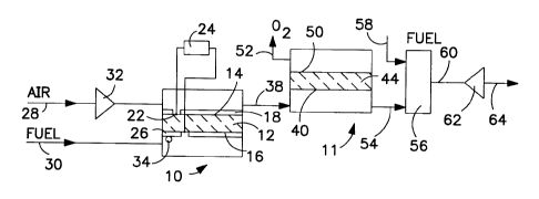
Figure 1 schematically illustrates a process
integrating a solid oxide fuel cell 10 and a first ion
transport reactor 11 in accordance with the invention.
The solid oxide fuel cell 10 has a ceramic membrane 12
that divides the solid oxide fuel cell 10 into a first
cathode side 14 and a first anode side 16.
The ceramic membrane 12 is oxygen selective and
transports oxygen ions from the first cathode side 14
to the first anode side 16. One suitable material for
the ceramic membrane 12 is ytria stabilized zirconia.
A porous air electrode 18 covers substantially all of
the first cathode side 14. One suitable material for
the air electrode 18 is strontium doped lanthanum
manganite. A first interconnect portion 22 is not
coated with the air electrode 18 and is electrically
connected to a load 24. Oxygen ions are transported
through the ceramic membrane 12 to the first anode side
16 that is coated with a porous fuel electrode 26
except for an electrical interconnect portion. Fuel
electrode 26 that may be made of any material that
effectively minimizes polarization losses and is stable
CA 02273550 1999-06-02
D-20633
- 11 -
in the reducing atmosphere such as a nickel-zirconia
cermets.
An oxygen-containing gas feed 28 is delivered to
the first cathode side 14 and a gaseous fuel 30 is
delivered to the first anode side 16.
The oxygen-containing gas feed 28, typically air,
is delivered to the cathode side of the fuel cell at a
temperature somewhat below (typically 200 to 700°C
below) the operating temperature of the fuel cell to
act as heat sink for the heat generated by the fuel
cell reaction. The operating temperature of the solid
oxide fuel cell 10 is typically at a temperature above
500°C and preferably in the range of from about 700°C
to about 1,000°C. Oxygen molecules in the feed air are
dissociated to elemental oxygen on contact with air
electrode 18. "Elemental oxygen" refers to oxygen that
is uncombined with other elements of the periodic
table. While typically in diatomic form, the term
elemental oxygen as used herein is intended to
encompass single oxygen atoms, triatomic ozone and
other forms uncombined with other elements. Air is
preferred as the oxygen-containing gas feed 28.
The oxygen-containing gas feed 28 is preferably
compressed, typically to a pressure of between 30 and
300 psia, and more preferably to a pressure of between
100 to 230 psia, by compressor 32. The compressed
oxygen-containing gas feed is then preferably warmed to
an intermediate temperature of between about 300°C and
about 800°C, and more preferably to a temperature of
from about 500°C to about 700°C, and then delivered to
the first cathode side 14. The final heating of the
CA 02273550 1999-06-02
O-20633
- 12 -
feed air to fuel cell and oxygen transport membrane
operating temperatures occurs within the fuel cell by
virtue of the portion of the chemical energy of the
anode side reaction which is not converted into
electrical energy but is released as heat which in turn
is transferred to elevate the temperature of the feed
stream to the required level.
The gaseous fuel 30 is any gas or combination of
gases having a constituent that exothermally reacts
with elemental oxygen. The reactive constituent may be
natural gas or mixtures of light hydrocarbons, methane,
carbon monoxide, or synthesis gas ("syngas"). Syngas
is a mixture of hydrogen and carbon monoxide with a
HZ/CO molar ratio of from about 0.6 to about 6. A
further component of the fuel gas, which may be
undesirable in the fuel cell, in some embodiments is a
non-reactive diluent gas such as nitrogen, carbon
dioxide or steam.
The gaseous fuel 30 is preheated to a temperature
of from about 300°C to about 900°C and then introduced
to the first anode side 16. The reactive constituents
of the gaseous fuel 30 exothermally react with
elemental oxygen. Electrons 34 released by the oxygen
ions provide electrical power to load 24.
A portion of the oxygen contained in the
oxygen-containing gas feed 28 is consumed by the
reaction at the first anode side 16. A retentate
stream 38 with reduced oxygen content is then conducted
to a second cathode side 40 that is a portion of a
first ion transport reactor 11.
CA 02273550 1999-06-02
O-20633
- 13 -
The first ion transport reactor 11 has an oxygen
selective ion transport membrane 44 that separates the
first ion transport reactor 11 into a second cathode
side 40 and a second anode side 50. By "oxygen
selective" it is meant that oxygen ions are
preferentially transported across the oxygen selective
ion transport membrane 44, from the second cathode side
40 to the second anode side 50, over other elements,
and ions thereof. The oxygen selective ion transport
membrane 44 is made from inorganic oxides, typified by
calcium- or yttrium- stabilized zirconia. At elevated
temperatures, generally in excess of 400°C, the oxygen
selective ion transport membrane 44 contains mobile
oxygen-ion vacancies that provide conduction sites for
the selective transport of oxygen ions through the
membrane. Transport through the membrane is driven by
the ratio of partial pressure of oxygen (Po2) across
the membrane: 0--ions flow from the side with high Po2
to the side with low Po2. Ionization of Oz to 0-- takes
place at the second cathode side 40 and the ions are
then transported to the second anode side 50 where OZ
is recoverable as a product gas.
The oxygen selective ion transport membrane 44 is
formed as either a dense wall solid oxide mixed or dual
phase conductor, or alternatively, as a thin film solid
oxide mixed or dual phase conductor that is supported
on a porous substrate. The oxygen-selective ion
transport membrane 44 has a nominal thickness of under
5,000 microns and is preferably less than 1,000 microns
thick.
The oxygen selective ion transport membrane 44
transports oxygen ions and electrons at the prevailing
.~ I: i
CA 02273550 2002-11-27
D-20633
- - 14 -
oxygen partial pressure in the temperature range of
from about 450°C to about 1200°C when a chemical
potential difference is maintained across the ion
transport membrane surface caused by a ratio of oxygen
partial pressures across the ion transport membrane.
The oxygen ion conductivity is typically in the range
of between 0.01 and 100 S/cm where S ("Siemens") is
reciprocal ohms (1/S~). Suitable materials fox the
oxygen selective ion transport membrane include
perovskites and dual phase metal-metal oxide
combinations as listed in Table 2 of U.S. Patent No.
5,733,435~ See also the materials disclosed
in U.S. Patent Nos. 5,702,999 (Mazanec) and 5,712,220
(Carolan et al.) A material with a high ion
conductivity, at least 0.5 and preferentially at least
1 S/cm at 900°C, is desired for membrane 44 since the
driving force for oxygen transport will typically be
small( < 10° ). A suitable material would be a mixture
of lanthanum, strontium and cobalt oxides.
,20 Optionally a porous catalyst layer, in some
embodiment made from the same perovskite material as
the material of the dense membrane layer, is added to
one or both sides of the oxygen selective ion transport
membrane 44 to enhance oxygen surface exchange in the
chemical reactions on the surfaces. Alternatively, the
surface layers of the oxygen selective ion transport
membrane 44 may be doped, for example, with cobalt, to
enhance surface exchange kinetics.
The first iron transport reactor 11 is operated at
an elevated temperature that is sufficient to
facilitate oxygen transport through the oxygen
CA 02273550 1999-06-02
D-20633
- 15 -
selective iron transport membrane 44. The operating
temperature is at least 400°C, preferably in the range
of from about 400°C to about 1,200°C, and most
preferably in the range from about 400°C to about
1,000°C.
Approximately 30$ to 60$, by volume, of the oxygen
retained in the reduced oxygen gas feed output is
transported through the oxygen selective ion transport
membrane 44 and is recovered as oxygen product gas 52.
The percentage of oxygen that can be recovered depends
on the respective oxygen partial pressures at the
second cathode side 40 and second anode side 50. The
percentage of oxygen recovered can be enhanced by
reducing the oxygen partial pressure at the second
anode side 50 by the use a sweep gas at the second
anode side or vacuum pumping.
Purge gases are oxygen scavenging gases such as
natural gas, methane, methanol, ethanol and hydrogen.
A sweep gas is a non-reactive gas that reduces the
oxygen partial pressure. Suitable sweep gases include
carbon dioxide and steam.
Optionally an oxygen depleted retentate stream 54
is directly expanded in a turbine 62 to generate
turbine power 64 or it may be delivered first to a
combustor 56 and reacted with a second gaseous fuel 58.
The combustion products 60 are a high temperature gas
of low oxygen content that may be used to drive the
turbine 62 to generate a turbine shaft power 64.
The efficiency of the process illustrated in
Figure 1 is enhanced by the arrangement illustrated
schematically in Figure 2. A recuperative heat
exchanger 66 recovers heat rejected from elevated
temperature gases such as product gas 52, combustion
CA 02273550 2002-11-27
D-20633
- 16 -
products 68 of solid oxide fuel cell 10, and combustion
products 60 of combustor 58: Optionally, the oxygen
depleted output 54 bypasses combustor 56 and rejects
heat to recuperative heat exchanger 66. The heat is
used to raise the temperature of the oxygen-containing
gas feed 28 and the gaseous fuel 30.
The combustion products 68 may be discharged after
recovery of waste heat as illustrated in Figure 2.
Alternatively, the combustion products 68 are conducted
to the second anode side 50 as a sweep gas, shown in
phantom as arrow 68a, to enhance oxygen transport and
recovery. In this alternative embodiment, the product
gas 52 contains oxygen, water and carbon dioxide.
After condensing out the water, a low purity oxygen
stream diluted by carbon dioxide is recovered. If
desired, the oxygen and carbon dioxide product gases
can be separated by a downstream process such as
thermal swing adsorption or polymeric membranes.
Reactive purge arrangements are disclosed in
"Reactive Purge for Solid Electrolyte,Membrane Gas
Separation", U.S. Patent No. 5,837,125,
E.P. Publ. No. 778,069. Preferred
configurations for ion transport modules utilizing a
reactive purge are disclosed in "Solid Electrolyte
Ionic Conductor Reactor Design", U.S. Patent No.
5,820,655. Both patents are commonly owned with
the present application.
The oxygen depleted retentate 54, Fig. 2,
contains between 6$ and 12~, by volume, of residual
oxygen and may be discharged 70 after rejecting heat to
recuperative heat exchanger 66, or alternatively, a
.,
,. ~i ~ , . ~ t '~. ~. 'i
CA 02273550 2002-11-27
D-20633
- 17 -
portion 70', or all, of the oxygen depleted retentate
is expanded in turbine 62 to recover power.
Since the.oxygen depleted retentate 54 contains
some residual oxygen, a combustor 56 may be inserted
upstream of turbine 62 and the oxygen depleted
retentate reacted with second gaseous fuel 58 to raise
the turbine 62 inlet temperature to between 1100°C and
1500°C thus increasing both the power generated and the
thermal efficiency of the system.
In the absence of combustor 56 or if expanded
stream 60 is at too low a temperature, the energy
required to sustain operation of the integrated system
illustrated in the Figure 2 is provided by the heat
generated in the solid oxide fuel cell 10. The amount
of heat generated depends on~the efficiency of the
solid oxide fuel cell 10 in converting chemical energy
'to electrical energy. This efficiency, in turn,
dictates the portion 70' of the oxygen depleted
retentate stream 54 that may be expanded in the turbine
62 since, if the heat generated by the solid oxide fuel
cell 10 is inadequate, a larger portion of the heat
contained within stream 54 must be used in recuperative
heat exchanger 66.to preheat the oxygen-containing gas
feed 28 and gaseous fuel 30.
. 25 In an alternative embodiment, the recuperative
heat exchanger 66 is replaced by a combustor (not
shown) that is positioned upstream of the solid oxide
fuel cell l0 to preheat the oxygen-containing gas feed
28 and gaseous fuel 30.
Figure 3 schematically illustrates an application
of the integrated system that provides both oxygen and
steam to a coal gasifier. As disclosed in.
I
CA 02273550 2002-11-27
D-20633
- 18 -
commonly owned, U.S. Patent No. 5,964,922:
coal gasifiers require both steam .
and oxygen, typically at a molar ratio of about 1:2 and
at elevated pressure.
In this embodiment, air stream 28, fuel stream 30,
and combustion products stream 68 from fuel cell 10 are
similar to those of Fig. 2. Retentate stream 54 of
module 11, Fig. 3, is passed directly through heat
exchanger 66 and/or through combustor 56' and turbine
62'. The second anode side 50 of module 11 is swept
with steam 72 to enhance oxygen transport through the
oxygen selective ion transport membrane 44 by lowering
the average oxygen partial pressure on the second anode
side 50. The advantages of steam sweeping are
discussed in commonly owned, U.S. Patent No.
5,954,859.
The steam 72 is a part of a process loop 73
integrated into the fuel cell/ion transport module
system. Feed water 74 is pumped to a required
pressure, typically on the order of 150 to 600 psi, by
pump 76 and then evaporated and superheated, such as in
recuperative heat exchanger 66, to produce the steam
72. Permeate stream 78 contains a mixture of residual
oxygen and steam. Stream 78, in a first embodiment, is
directly injected into a coal gasifier 80 (shown as
stream 102, but without the addition of stream 100',
described below).
In a second embodiment, the stream 78 is divided
into a first portion 82 injected into coal gasifier 80
i. _
' o ' ~'
CA 02273550 1999-06-02
~-20633
- 19 -
and a second portion 84 that is expanded in turbine 63,
cooled and delivered to a condenser 86. Most of the
steam is condensed in condenser 86 and the condenser
output 88 is a mixture of liquid water and water
saturated oxygen. The water is separated from the
mixture in a separator 90 and recycled water 92 is
mixed with make up feed water 74.
Water saturated oxygen 94 removed from separator
90 is cooled in a cooler 96 and compressed in
compressor 98. The compressed stream 100 is reheated,
such as by passing through recuperative heat exchanger
66 as heated stream 100' and then blended with the
first permeate stream portion 82 to produce stream
102. By controlling the proportion of first portion 82
and compressed stream 100 to make up stream 102, the
desired steam to oxygen ratio for coal gasifier 80 is
obtained.
Advantages of the system schematically illustrated
in Figure 3 over a separate generation and injection of
steam and oxygen to a coal gasifier include a reduction
in required ion transport membrane area and savings in
the power required to compress oxygen. By blending a
stream containing steam and oxygen with a second, high
oxygen content stream, better control of the steam to
oxygen ratio is achieved. Using steam as a sweep gas
permits operating the cathode sides of the fuel cell
ion transport reactor at pressures lower than gasifier
pressure while saving oxygen compression power.
Alternatively, a condenser (not shown) may be used
to remove water from output 78 to obtain a lower steam
to oxygen ratio. This alternative, however, wastes
much of the energy contained within that portion of the
CA 02273550 1999-06-02
D-20633
- 20 -
output 78 that is condensed reducing the efficiency of
the system.
Figure 4 schematically illustrates an integrated
system having a solid oxide fuel cell 10 and a first
ion transport reactor 11 useful for the co-production
of power and nitrogen. Oxygen-containing feed gas 28,
typically air, is compressed by compressor 32 to a
pressure of between about 45 and 165 psia. The
compressed air is then heated, such as by recuperative
heat exchanger 66 to a temperature of between about
200°C and 700°C and introduced to the first cathode
side 14 of fuel cell 10. Approximately 60o to 700, by
volume, of the oxygen contained within the
oxygen-containing gas feed 28 is transported through
ceramic membrane 12 and exothermally reacts with the
gaseous fuel 30. By maintaining a relatively high
pressure on the first cathode side 14, a relatively
high oxygen partial pressure is maintained enabling a
significant volume fraction of the oxygen to be
transported through the ceramic membrane 12 and thus
obtaining reasonable conversion efficiency. Due to the
significant exothermic reactions occurring at the first
anode side 16, additional cooling may be required to
avoid an excessive temperature rise.
The retentate 38 having reduced oxygen content is
delivered to the first ion transport reactor 11 to
complete removal of oxygen from the cathode side
stream. The oxygen is transported through the oxygen
selective ion transport membrane 44 and exothermally
reacts with gaseous fuel 30' at the second anode side
50. The heat from this exothermic reaction is absorbed
within a heater section 39 by temperature rise of the
cathode side feed stream 38' which as stream 38 was
CA 02273550 1999-06-02
D-20633
- 21 -
cooled in heat exchanger 66 or in optional cooler 66'.
Stream 54 retentate contains less than about 10 ppm of
oxygen and can be delivered at pressure as a high
pressure nitrogen product 104 after the removal of
useful heat by recuperative heat exchanger 66.
Alternatively, at least a portion of the oxygen
depleted stream 54 is expanded in turbine 62 and
recovered as a low pressure nitrogen product 106.
A first portion of the gaseous fuel 30 is
delivered to the first anode side 16 of the solid oxide
fuel cell 10. A second portion 30' of the gaseous fuel
30 can be delivered directly to the second anode side
50 of the first ion transport reactor 11. Preferably,
the combustion products 68 serve as a diluent and are
combined at junction 108 with the second portion 30' of
the gaseous fuel 30 gas to purge the second anode side
50. Most preferably, all gaseous fuel 30 passes
through the first anode side 16 to increase the average
fuel partial pressure at the solid oxide fuel cell 10
anode and thereby maximize the efficiency of the fuel
cell since a high fuel partial pressure will enhance
the reaction kinetics on the fuel cell anode and
thereby minimize polarization losses.
The permeate gas 52 is substantially water vapor
and carbon dioxide, since nitrogen is excluded from the
anode side reactions, except for trace amounts
contained within the fuel. If desired, a carbon
dioxide product 109 may be recovered after condensing
out the water.
The system illustrated schematically in Figure 4
generates a significant excess of heat because all the
oxygen contained in the oxygen-containing gas feed 28
is exothermally reacted with gaseous fuel 30. In small
CA 02273550 1999-06-02
D-20633
- 22 -
systems, this heat may be used to generate steam to
export from the system. In larger systems, the excess
heat may be utilized to produce additional power
through a Rankine cycle 110, shown in phantom. In a
Rankine cycle, the excess heat is directed to a boiler
where the heat changes the water into superheated
steam. Expansion of steam to a lower pressure vapor
drives a turbine to generate shaft power. Heat is then
removed in a condenser as the steam is converted back
to a saturated liquid low pressure. A pump then
returns the pressure to the boiler pressure. Heat for
the Rankine cycle 110 is preferably removed from
streams 38 and/or 54.
Figure 5 illustrates a system for the
co-generation of nitrogen and oxygen. A second ion
transport reactor 112 is disposed between the solid
oxide fuel cell 10 and the first ion transport reactor
11. An oxygen-containing gas feed 28, typically air,
is compressed to a pressure of between 100 psia and 300
Asia by a compressor 32 and heated, such as by
recuperative heat exchanger 66, to a temperature of
between about 300°C and about 800°C. The heated
oxygen-containing gas feed 28 is delivered to the first
cathode side 14. Approximately 20o to 250, by volume,
of the oxygen contained within the oxygen-containing
gas feed 28 is transported through the ceramic membrane
12 to exothermally react with gaseous fuel 30
generating electrical power delivered to load 24 and
heat. The heat is effective to raise the temperature
of the partially oxygen depleted retentate stream 38 to
a temperature in the range of from about 900°C to about
l, 000°C.
CA 02273550 1999-06-02
~-20633
- 23 -
The partially depleted oxygen gas stream 38 is now
at an effective temperature for oxygen separation in
the second ion transport reactor 112 and approximately
40o to 60~ of the remaining oxygen is transported
through a oxygen selective ion transport membrane 114
and recovered as oxygen product 116. A low
oxygen-containing retentate stream 118 discharged from
the second ion transport reactor 112 rejects heat to
heat exchanger 120. The rejected heat can be used for
an external Rankine power cycle, delivered to
recuperative heat exchanger 66 to make up thermal
deficiencies in other parts of the system, or
discharged as waste. A reduced temperature, typically
on the order of 300 to 700°C, low oxygen content stream
122 is introduced to the second cathode side 40 of the
first ion transport reactor 11. Typically, the oxygen
content in the feed gas to the cathode side 40 of the
first ion transport reactor 11 will be between 2o and
70, by volume, depending on whether a sweep gas (a
suitable source could be stream 52 consisting of
products of combustion) is introduced to the third
anode side 124 of the second ion transport reactor 112
to reduce the oxygen partial pressure at the third
anode side, thereby increasing the driving force for
oxygen transport through the oxygen selective ion
transport membrane 114. The lower value is achieved if
a sweep gas is used. The remaining oxygen is
transported through the oxygen selective ion transport
membrane 44 and exothermally reacted with either
gaseous fuel 30, or a mixture of fuel and combustion
product 60 where all fuel is introduced to the anode of
fuel cell 10, at the anode side 50 of the first ion
transport reactor 11. The retentate from cathode side
CA 02273550 1999-06-02
7-20633
- 24 -
40, oxygen depleted gas stream 54, typically has an
oxygen content of less than 10 parts per million.
As described above, the oxygen depleted gas stream
54 may be recovered as a high pressure nitrogen product
104, as low pressure nitrogen product 106 after stream
54' is expanded in power producing gas turbine 62, or a
combination thereof.
Product gas 52 from the second anode side 50 may
be cooled to recover carbon dioxide 109 and water
vapor. Alternatively, the product gas 52 may be
delivered to the anode side 124 of the second ion
transport reactor 112, in which case the permeate
stream 116 contains a mixture of carbon dioxide, oxygen
and water vapor. If the water vapor is removed, such
as by condensation, the gas will contain about 75o to
920 oxygen by volume. Pure oxygen is obtained, after
separation and recovery of the carbon dioxide and
additional drying.
The advantages of the invention described herein
above will become more apparent from the examples that
follow:
Example 1
Figure 6 schematically illustrates a system that
integrates a solid oxide fuel cell 10, a first ion
transport reactor 11 and a second ion transport reactor
112 to co-produce electric power for load 24, oxygen as
product gas 52 and high pressure nitrogen 104 and low
pressure nitrogen 106. The nitrogen product streams
are proportioned so that the power produced by gas
turbine 138 is just sufficient to drive air compressor
32.
CA 02273550 1999-06-02
D-20633
- 25 -
An oxygen-containing gas feed 28, air, is
compressed by compressor 32 to a pressure of about 155
psia and after having been preheated in recuperative
heat exchanger 66 is delivered to the first cathode
side 14 and where it is further heated to a temperature
of about 950°C due to heat generated by the exothermic
reactions occurring at the first anode side 16. The
solid oxide fuel cell 10 generates electric power that
is withdrawn and after conditioning delivered to the
load 24, such as an external power grid. The oxygen
content of the partially depleted oxygen gas stream 38
is approximately 15$, by volume.
Stream 38 is delivered to the third cathode side
126 of the second ion transport reactor 112. Oxygen
corresponding to 12$ of that contained in the feed air
is transported through the second oxygen selective ion
transport membrane 114 such that the oxygen content of
retentate stream 118 contains about 6$ oxygen, by
volume. Stream 118 is at an elevated temperature and
rejects heat in a first superheater 128 to steam stream
130. Stream 122, now at reduced temperature, is
introduced to the second cathode side 40 where the
residual contained oxygen is removed by a reactive
purge gas stream 68, typically consisting of fuel and
combustion products coming from the first anode side
16, of the first ion transport reactor 11.
The oxygen depleted stream 54, now a high purity
nitrogen stream, is split or divided at junction 132
into a first stream 134 which is recovered as high
pressure nitrogen product 104 and a second stream 136
which is expanded in turbine 138 which drives the
compressor 32. The split between streams 136 and 134
is proportioned such that the power delivered by
CA 02273550 1999-06-02
D-20633
- 26 -
turbine 138 satisfies the requirements of the
compressor 32 when the turbine and compressor are
mechanically coupled. The flow in excess of that
required is recovered as high pressure nitrogen product
104. Waste heat from the expanded second stream 140 is
recovered by the Rankine cycle 110 before discharge
from the system as low pressure nitrogen stream 106.
The gaseous fuel 30 is heated in recuperative heat
exchanger 66 and delivered to the first anode side 16.
At the first anode side 16, the gaseous fuel 30 reacts
exothermally with transported oxygen to produce
electric power and heat. The permeate stream 68
exiting the first anode side 16 contains excess
unburned fuel and combustion products and is
introduced to the second anode side 50 of the first ion
transport reactor 11 to serve as the reactive purge
stream for removal of residual oxygen from the
partially oxygen depleted gas feed 122. The permeate
144 from the second anode side contains primarily the
products of combustion (carbon dioxide and water vapor)
and is discharged after recovery of useful heat in
recuperative heat exchanger 66.
Alternatively, the gaseous fuel 30 is compressed
by a conventional element (not shown) and the first
anode side 16 and the second anode side 50 are then
operated at about the same pressure as the first and
second 40 cathode sides 14 and 40. If this is done,
the anode side products of combustion can be delivered
at pressure for enhanced downstream recovery of carbon
dioxide or, if carbon dioxide co-product is not
desired, added to the second high pressure nitrogen
stream 136 and expanded. This will permit recovery of
i~ , ~.. ~-Ili ..
CA 02273550 2002-11-27
D-20633
. - 27 -
additional high pressure nitrogen as product 104 or the
export of additional power.
The third anode side 124 is purged by a sweep gas
(steam in this construction) generated by pumping feed
water 74 by pump 76 to a pressure of about 1,000 psia
and delivering it to a boiler/heater 146 that converts
it to steam 130. The steam is then superheated in a
second superheater 148 to a temperature that is
sufficient to avoid moisture condensation during
subsequent expansion to a pressure of about 150 psia in
high pressure turbine 150.
The expanded steam 130 is reheated in first
superheater 128 and used to purge the third anode side
124. This improves oxygen recovery and increases the
driving force for oxygen transport. Such an
application for a steam circuit is more fully disclosed
in commonly owned, U.S. Patent No. 5,954,859.
Stream 78 has a partial pressure of oxygen of
about 20 psia and is delivered to a low pressure steam
turbine 152 at a pressure of about 150 psia. The
expanded output 154, now at a pressure of 16 Asia, is
then cooled in the second superheater 148 providing the
heat required to superheat steam 130. The cooled,
expanded output stream 156 enters condenser 158 where a
major portion of the contained water condenses,
permitting recovery of the oxygen as product gas 52
from separator 90. Recycled water 92 may be combined
with the feed water for return to pump 76 and thereby
returned to a pressure of 1,000 psia to complete the
30steam circuit.
.,
CA 02273550 1999-06-02
D-20633
- 28 -
Table 1 identifies the inputs utilized to model
the system illustrated in Figure 6.
Table 1
FIGURE 6, REF.
PARAMETER VALUE NUMERAL
Air Flow 8.33 MiHNCFH 28
Air Compressor 155 psia (4 32
Discharge Pressure Compression Stages)
Air Compressor 85~ adiabatic 32
Efficiency
SOFC temperature 950C 10
SOFC Efficiency 60$ 10
Hot Gas Turbine Inlet150 psia 138
Pressure
Hot Gas Turbine Inlet950C 138
Temperature
Hot Gas Turbine 16 Asia 138
Exhaust Pressure
High Pressure Steam 1,000 psia 150
Turbine Inlet Pressure
High Pressure Steam 430C 150
Turbine Inlet
Temperature
Low Pressure Turbine150 psia 152
Inlet Pressure
Low Pressure Steam 900C 152
Turbine Inlet
Temperature
Low Pressure Steam 16 Asia 152
Turbine Exhaust
Pressure
Steam Condensing 14.7 psia 158
Pressure
Steam Generated 303 M lbs./hr. 130
CA 02273550 1999-06-02
D-20633
- 29 -
The calculated results for the system are
tabulated in Table 2.
Table 2
FIGURE 6, REF.
PARAMETERS VALUE NUMERAL
Oxygen Product 1,000 MNCFH 57~ 52
at 1 Rec.
atm. of OZ in Air
Nitrogen Product 2,990 MNCFH 104
at
9.86 atm.
Net Power Generated98,100 KW 36
Heat Required 711 MM BTU/Hr. For System
Heat Rate 7,247 BTU/KW Hr. For System
Heat Rate with 6,766 BTU/KW Hr. 66
Credit for N2
Compression
Heat Rate with 6,344 BTU/KW Hr. 112
Add.
Credit for Sep.
at
7KW/1,000 NCFH
02
The Table 2 results display a very attractive
performance potential in terms of the heat rates
realized notwithstanding the relatively modest peak
temperatures employed in the cycle while obtaining
respectable oxygen recoveries in comparison to
conventional systems. As further benefit, a
significant fraction of the nitrogen contained in the
air is delivered at pressure.
Example 2
Figure 7 schematically represents another
integrated system in accordance with the invention.
This system is particularly effective for the
production of essentially oxygen-free nitrogen with the
option for the co-production of oxygen and carbon
dioxide. Utilizing the parameters presented in Table 3
CA 02273550 1999-06-02
D-20633 '
- 30 -
below, the solid oxide fuel cell 10 is sized to deliver
sufficient power to drive the air compressor 162.
An oxygen-containing gas feed 28, preferably air,
is compressed by air compressor 162 to a pressure of
about 155 psia. The compressed air is then preheated,
such as by recuperative heat exchanger 66, to a
temperature of about 800°C and introduced to the first
cathode side 14 of the solid oxide fuel cell. Gaseous
fuel 30 is introduced to the first anode side 16 and
exothermally reacted with oxygen ions transported
through the ceramic membrane 12 generating heat,
electricity and anode side stream 68 that is a mixture
of combustion products and gaseous fuel. The electric
power generated is utilized to drive an electric motor
164 that drives the air compressor 162.
The partially oxygen depleted retentate stream 38
exiting the solid oxide fuel cell 10 is at a
temperature of about 950°C. About 120, by volume, of
the oxygen contained in the air is consumed by the
reaction with the gaseous fuel 30 at the first anode
side 16. Partially oxygen depleted stream 38 is
conducted to the third cathode side 126 of the second
ion transport reactor 112 where about 600, by volume,
of the remaining oxygen is transported through the
second oxygen selective ion transport membrane 114. To
enhance the removal and potential recovery of a
significant fraction of the oxygen contained within the
stream 38, the third anode side 124 is swept with the
combustion products of either the first anode side 16,
the second anode side 50 or the combination of both.
The sweep gas reduces the oxygen partial pressure at
the third anode side 124 to increase oxygen recovery
and or the driving potential for oxygen transfer.
CA 02273550 1999-06-02
D-20633
- 31 -
Retentate stream 118 from the third cathode side
126 contains about 6$, by volume, of oxygen. Stream
118 is cooled in heat exchanger 166 producing a reduced
temperature stream 122 to function as a heat sink 168
to absorb the heat of reaction generated downstream in
first iron transport reactor 11. The heat rejected
from the low oxygen content retentate stream 118 in
heat exchanger 166 can be used to raise steam 170 for
export or other uses.
The reduced temperature stream 122 is delivered to
the second cathode side 40 where the remainder of the
contained oxygen is transported through the oxygen
selective ion transport membrane 44 and reacts with the
gaseous fuel contained within the gaseous
fuel/combustion products mixture 68 at the second anode
side 50. The oxygen depleted gas stream 54 removed
from the second cathode side 40 contains less than 10
ppm oxygen and can be delivered, after recovery of
useful heat, as a high pressure nitrogen product 104.
The gaseous fuel 30 is preheated in recuperative heat
exchanger 66 and delivered to the first anode side 16
and reacts with oxygen transported through ceramic
membrane 12 from the first cathode side 14. Since the
gaseous fuel 30 contains also the fuel required in the
first oxygen transport reactor 11, the average partial
pressure of the gaseous fuel in the solid oxide fuel
cell 10 is elevated to enhance efficiency. The exiting
permeate stream 68 contains gaseous fuel diluted by the
products of combustion and enters the second anode side
50 of the first ion transport reactor 11 to remove
oxygen transported through the ceramic membrane 44 from
the second cathode side 40 by a reactive purge. The
exiting permeate stream 144 contains combustion
CA 02273550 1999-06-02
D-20633
- 32 -
products, a mixture of water vapor and carbon dioxide,
and is useful as a sweep gas to purge the third anode
side 124 of the second ion transport reactor 112.
Permeate stream 78 exiting from the second ion
transport reactor 112 contains a mixture of combustion
products and oxygen. Following the recovery of useful
waste heat in recuperative heat exchanger 66, condenser
158 and separator 160 are utilized to recover a low
purity oxygen product gas 52 that contains about 75$,
by volume, of oxygen with the bulk of the impurities
being carbon dioxide. If required, the carbon dioxide
could be removed by a downstream process and the oxygen
recovered. Recycled water 92 is appropriately
discharged. If the oxygen or carbon dioxide are not
desired, stream 78 may also be discarded after recovery
of useful heat in recuperator 66.
Table 3 identifies the input parameters for the
system schematically illustrated in Figure 7.
Table 3
FIGURE 6, REF.
PARAMETER VALUE NUMERAL
Air Flow 126,000 NCFH 28
Compressor Discharge150 Asia 162
Pressure
No of compression 3 162
stages
Adiabatic Compressor85$ 162
Efficiency
SOFC Efficiency 60$ 10
SOFC Operating 950C 10
Temperature
CA 02273550 1999-06-02
D-20633
- 33 -
The results of the calculations utilizing the
inputs of Table 3 are tabulated in Table 4.
Table 4
FIGURE 7, REF.
PARAMETERS VALUE NUMERAL
Nitrogen Product 100,000 NCFH 104
at
< 10 ppm 02
Nitrogen Product 140 psia 104
Pressure
Nitrogen Recovery 100 104
Potential Oxygen 16,120 NCFH 52
Byproduct contained at 75.9$
Purity
Byproduct Pressure14.7 psia 52
Oxygen Recovery 61~ 52
Potential Stream 2,900 Lbs./Hr. 170
for
Export
Required Fuel 5,100 NCFH of 30
Natural Gas
An advantage of the system illustrated in Figure 7
is that the efficiency is enhanced by the availability
of fuel diluent, in the form of combustion products
from the solid oxide fuel cell 10, and the first ion
transport reactor 11 to purge the second ion transport
reactor 112. This enables high recovery rates of both
nitrogen and oxygen. A nonintegrated (separate fuel
cell powering the compressor or an independent ion
transport membrane) separation system would be burdened
by additional capital expenditure for the separate air
and fuel circuits, the capital and energy penalties due
to a larger fuel cell which is required to supply the
air compression power for both systems and greater
energy penalties due to cold end temperature
differential losses, likely resulting in less efficient
fuel utilization.
CA 02273550 1999-06-02
D-20633
- 34 -
The specific features of the invention are shown
in one or more of the drawings for convenience only, as
each feature may be combined with other features in
accordance with the invention. Alternative embodiments
will be recognized by those skilled in the art and are
intended to be included within the scope of the claims.