Note: Descriptions are shown in the official language in which they were submitted.
CA 02273684 1999-06-04
1
ARRANGEMENT FOR DRYING SECTION OF PAPER MACHINE
The invention relates to an arrangement for a drying section of a
paper machine, the arrangement comprising a fine wire and a coarse wire
which are formed of several threads and withstand high temperatures and
humidity, the wires being arranged to pass through the drying section between
a heated and a cooled metal band provided in the drying section, together with
a fibre web placed against the heated band, such that the fine wire is
arranged
against the web to be dried and the coarse wire is arranged against the cooled
metal band.
Paper machine fabrics, such as wires and felts, are used in different
machines producing a web-like product from a pulp, such as paper machines,
board machines or the like, which will be referred to herein as 'paper
machines'. Paper machine fabrics are used at the wet end, the press section
and the drying section of the paper machine for forming a web and guiding it
via the different stages of the machine. At the beginning of the paper
machine,
a pulp is supplied to the wire for forming a web, and felts and wires are used
in
the press and drying sections of the machine. In the press section, water can
be removed from the web when it is pressed for drying it before final drying
by
heat. When in use, paper machine fabrics rotate around different rolls and
cylinders at a rate equal to that of the web.
A paper machine fabric is typically made of different threads of
possibly varying cross-sections and materials in order to provide desired
properties. Thread materials used include polyester, polyamide and other
monofilament and multifilament threads. The manufacture of the fabrics
employs different binding structures and combinations thereof, which should
provide the fabric with desired properties suitable for the intended use.
Dryer
screens must operate under varying conditions, which means that sometimes
they are subjected to heat and humidity and at other times to heat and
drought. Further, a dryer screen is required to have good dimensional
stability
and durability as well as flexibility.
Typical paper machine fabrics include dryer screens used to guide
the paper web to be dried through the drying section and to support the web
so that the finished fibre web comprises as little marking as possible
resulting
from the texture of the wire, whereas the permeability and behaviour of the
wire in the drying section is as desired. In dryer screens the object is to
CA 02273684 1999-06-04
2
achieve as even and dense a surface structure as possible, in other words a
high thread density, so that the web surface would be as smooth as possible.
Usually the web is placed against the smoother surface of the dryer screen so
that the occurrence of marking in the web can be prevented.
The drying of a fibre web may utilize a band dryer unit disclosed in
Finnish Patent Application 944,775, wherein a fibre web is dried between two
parallel metal bands moving in the same direction such that the web touches a
heated metal band, and between the fibre web and the other, cooled metal
band there is a wire so that as a result of heating the steam that evaporates
from the fibre web is condensed in the wire due to the cold metal band. The
wires may be bands made in the shape of a closed loop, or alternatively,
bands that are connected together from their free ends to form a closed loop.
A fibre web, a fine wire or fine felt and a coarse wire are carried between
the
upper band and the lower band through the drying section. The operation of
the band dryer is based on the heating of the upper band that is in contact
with
the web, so that the water in the web evaporates due to the temperature of the
upper band and it is transferred through the fine wire and the coarse wire
towards the lower band. The lower band, in turn, is cooled so that steam
produced on the surface of the band is condensed into water and it is
discharged with the lower band and the coarse wire positioned against the
lower band. The fine wire preferably comprises a plurality of permeable flow
conduits. Free flow in the direction of the wire level can be equal in all
directions, or stronger in one direction, or the flow may be prevented in any
direction, if required. Further, the coarse texture should have a sufficient
water
retention capacity. The coarse texture of the coarse wire situated against the
cooled metal band is not always able to retain the water that is condensed on
the side of the cooled metal band; as desired, but some of the water may be
able to disadvantageously move back towards the web. This so-called
rewetting naturally reduces the efficiency of the dryer and causes problems in
the following stages of the paper machine.
The purpose of the present invention is to provide an arrangement
for a drying section in a paper machine, avoiding the drawbacks of the prior
art
and enabling more efficient drying of a web than previously.
The arrangement according to the invention is characterized in that
the fine wire comprises at least three interwoven layers, wherein surface
CA 02273684 1999-06-04
3
layers arranged against the web and the coarse wire are denser than a middle
section situated between them.
The basic idea of the invention is that between the web to be dried
and the cooled metal band of the band dryer the arrangement comprises a fine
wire placed against the web and a coarse wire provided against the metal
band. The fine wire is formed such that it comprises at least three interwoven
textural layers. Further, the surface layers of the fine wire, in other words
the
side of the wire facing the paper and the side facing the coarse wire have a
denser texture than the section situated between the layers. The basic idea of
a preferred embodiment of the invention is that the surface layer of the fine
wire facing the web is formed with the densest texture, the middle section of
the wire has a looser texture, and the bottom of the wire facing the coarse
wire
is again formed with a dense texture, which is not as dense, however, as the
surface layer of the wire facing the web. As regards the density of its
structure,
such a wire is asymmetrical with respect to the central axis of the wire. The
basic idea of another preferred embodiment of the invention is that the
textural
structure of the fine wire is formed such that the threads in the machine
direction or the warp threads are sheltered by the transverse weft threads
almost along their entire length in the texture, wherefore the wearing effect
and the pressure acting on the wire affect more the weft threads which are not
significant for a wire break.
The invention has an advantage that due to its structure the fine
wire can be made stiffer than previously, which means that it is suitable for
use
also in a situation where the coarse wire is arranged to travel between the
bands so that the coarse side thereof faces the fine wire and the smoother
side of the coarse wire faces the cooled metal band. In such a case, the
stiffer
fine wire according to the invention does not press into depressions and
openings of the coarse wire resulting from its rough surface texture, but it
is
positioned suitably as an even surface, thus preventing the occurrence of
marking in the web. The rougher surface texture of the coarse wire is
therefore
not able to produce marking on the web through the fine wire. The structure
according to the invention with three or more layers where the outermost
sections are made of a finer texture than the middle section form a sandwich
structure which is advantageous in the production of stifF constructions. Due
to
such a structure, the fine wire may also be thin but still sufficiently stiff
to
prevent the occurrence of marking through the fine wire. A thin fine wire is
CA 02273684 1999-06-04
4
advantageous especially in high-speed drying apparatuses, since a thin wire
does not transport as much air between the bands as a thicker wire.
Furthermore, a thin wire can be dried more easily after the washing than a
thick wire before it is passed again between the bands of the drying
apparatus.
In the future development of the band dryer, the temperature of the hot band
is
raised continuously in order to improve the efficiency, which in turn sets
higher
and higher standards also for the wires to be used. Also, possible preheating
of a fine wire must be taken into account when planning the behaviour of the
wire during a run. A fine wire according to the invention also solves the
aforementioned problems since due to its structure it is more stable and has
better dimensional stability than previously, in other words it can be used
better even at high temperatures without the occurrence of disadvantageous
stretching, narrowing or other dimensional changes of the fine wire that would
affect the quality of the drying. Another advantage is that the fine-textured
bottom of the fine wire facing the coarse wire wears the coarse wire less and
also wears itself down less than the fine wire used in the prior solutions
where
the bottom section facing the coarse texture is rough. The wearing caused by
the movement of the fine wire and the coarse wire with respect to each other,
for example the difference in speed between the wires, can thus be decreased
by making the bottom of the fine wire smooth. The life of the wires can
therefore be increased. However, the dense outermost layers of the fine wire
do not prevent in any way the transfer of humidity through the fine wire, the
humidity still being in the form of steam as it penetrates the fine wire. A
further
advantage is that the fine wire no longer soils easily due to its dense outer
layers and the wire is therefore also easier to clean.
In this application, the terms 'fine texture' and 'dense texture' refer
to a layer with lower water or air permeability, a greater number of threads
per
surface area, or a layer with a greater contact area achieved with flatter
threads than in the other layers of the fabric. A dense fine texture may have
all
the aforementioned properties simultaneously. Such a dense layer can be
provided on the surfaces of the fine wire in several different manners. It is
possible to use either spun or doubled threads, threads with an oval or flat
cross-section, or a lower thread density together with thicker threads, or a
higher thread density and correspondingly thinner threads.
The invention will be described in greater detail in the
accompanying drawings, in which
CA 02273684 1999-06-04
Figure 1 is a schematic side view of a band dryer unit wherein an
arrangement according to the invention can be applied,
Figure 2 is a schematic sectional view of an arrangement according
to the invention applied in connection with a band dryer and viewed
5 transversely with respect to the direction of travel of the web, and
Figures 3a to 3i are schematic cross-sectional views of fine wires
according to the invention.
Figure 1 shows, in a simplified manner, a band dryer known per se,
in connection of which the arrangement according to the invention is to be
used. The structure and operating principle of the band dryer 1 are already
described above in the description of the background art, which will now be
referred to. A fibre web 4 to be dried is supplied between a heated upper band
2 and a cooled lower band 3 in a direction of travel A denoted in the figure,
together with wires 5a and 5b supporting the web which are passed together
through the dryer. The wires may consist of a woven paper machine fabric with
one or more layers, and they are usually bands in the shape of an endless
loop, made to travel around different rolls or the like, and they are
controlled
by the rolls. In the case shown in the figure, there are two wires between the
web and the cold band, but at least in principle it is possible to use even a
greater number of separate wires. The fabric placed against the web 4 to be
dried, shown uppermost in the figure, is a fine wire 5a and the lower fabric
is a
coarse wire 5b which may comprise a section with a coarse texture 5c placed
against the fine wire 5a and a section with a fine texture 5d placed against
the
cooled band 3. Such a structure of the coarse wire 5b is advantageous for the
dewatering capacity of the wire. It is generally required that a coarse wire
has
a sufficient water retention capacity so that it is capable of transporting
the
liquid that is separated from the fibre web 4 with the band dryer 1 from
between the upper and the lower band 2 and 3. The water retention capacity
can be adjusted by means of the thickness of the coarse wire and the textural
structure.
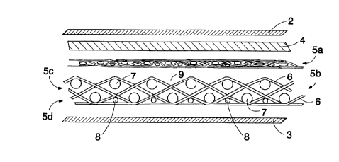
Figure 2 shows, in a very simplified manner, a cross-section of an
arrangement according to the invention viewed transversely to the direction of
travel of the web. The fabric supporting the web consists of a fine wire 5a
placed against the web 4 and a separate coarse wire 5b. It should be
mentioned that the different textural sections are shown separately from one
another for the sake of clarity. In actual use, the web to be dried between
the
CA 02273684 1999-06-04
6
metal bands is naturally pressed tightly together with the wires. In the
arrangement shown in the figure, the coarse wire 5b comprises a coarse-
textured section 5c facing the fine wire 5a, and steam that evaporates from
the
web is able to pass easily via the larger and more numerous openings thereof
through the coarse structure of the wire. The transfer of humidity is thus
effective. The coarse-textured section 5c of the coarse wire 5b facing the web
does not cause significant marking in the web 4 through the fine wire 5a, if a
slightly thicker fine wire is used than previously and/or if the structure of
the
fine wire is made more rigid so that it does not press into depressions 9
provided on the surface of the coarse side of the coarse wire. Therefore the
surface of the coarse wire facing the fine wire does not necessarily have to
have a fine texture or to be otherwise especially smooth and even. The
openings in the fine-textured section of the coarse wire are placed against
the
substantially even metal band, so that condensing humidity can be retained on
the surface of the coarse wire against the metal band by means of capillary
forces, wherefore the web will not get wet again. For the sake of
illustration,
the figure shows a possible textural structure of the coarse wire comprising
warp threads 6 in the machine direction, transverse weft threads 7 and filling
threads 8. The fine-textured sections can be formed in the fine wire and the
coarse wire for example by using thinner threads than in the coarser section
of
the wire, and a binding structure providing a closer texture. It is clear that
textural structures formed of other kinds of threads and bindings between
them are also possible.
In connection with the coarse wire described above which
comprises a coarse texture against the fine wire, it is preferable to use a
fine
wire shown below in Figures 3a to 3i, comprising at least three and preferably
exactly three interwoven layers: a surface 10 facing the web, a bottom 11
facing the coarse wire and a middle section 12 situated between them. The
density of the surface and the bottom is greater than that of the middle
section.
The close structure provided by means of the threads on the surface 10 of the
fine wire reduces marking, since a dense structure has more contact points
between which the contact pressure can be distributed. In such a case the
contact area is greater. The dense surface simultaneously prevents rewetting
and improves heat transfer capacity. Further, the surface is preferably made
such that the warp threads 6 in the machine direction are partly sheltered by
the rest of the structure so that they are not worn so easily on the side of
the
CA 02273684 1999-06-04
7
paper, wherefore the risk of a wire break occurring in the prior art fine
wires
can be prevented. In such a structure, the compression acting on the wire is
advantageously directed more towards the transverse threads than the
threads in the machine direction. This feature will be described below in
connection with Figures 3a to 3i. Further, the middle section 12, which is
provided with a looser texture than the surface and the bottom, improves the
transverse stability and bending stiffness of the fine wire. The middle
section
thus increases the strength of the wire. Further, by means of the middle
section it is possible to easily make the wire slightly thicker than normally,
if
required. The wire thickness is normally in the range of 0.6 to 0.7 mm, but by
making the loose middle section thicker the wire thickness can be easily
increased to about one millimetre and even more. However, when designing
the thickness of the middle section it should be taken into account that the
wire
does not transport too much air between the metal bands and cause an air
blow, and further, that the wire can be dried sufficiently after the washing
before it is passed again between the metal bands. On the other hand, if the
fabric can be made sufficiently stiff, the middle section and thus also the
entire
fine wire may be rather thin. The bottom 11 of the fine wire is made dense,
even and suitably stiff so that the wire cannot press into the uneven spots in
the coarse texture of the coarse wire. The middle section providing strength
also prevents the aforementioned pressing of the fine wire and thus the
marking. Furthermore, the smooth bottom prevents the wearing of the contact
surfaces of the coarse wire and the fine wire. Material for the threads of the
wire can be any suitable plastic material that withstands hydrolysis, for
example polyethylene terephthalate (PET), polyamide (PA), polyphenylene
sulphide (PPS), polyetheretherketone (PEEK), polydimethylene cyclohexylene
terephthalate (PCTA) or polyethylene naphthalate (PEN).
Figures 3a, 3d and 3g are simplified cross-sectional views of
possible structures of a fine wire viewed transversely with respect to the
direction of travel of the web. Figures 3b and 3c, 3e and 3f, and 3h and 3i
further show these wire structures in a cross-section viewed from the
direction
of travel of the web, shown from different points of the structure. The
textures
shown in Figures 3a - 3c, 3d - 3f and 3g - 3i thus correspond to each other,
but
they are shown from different directions. The fine wires 5a shown in the
figures comprise three interwoven layers, and the texture of the outermost
layers 10, 11 is denser than the texture of the middle section 12. Unlike the
CA 02273684 1999-06-04
structure shown in Figures 3a to 3f which is symmetrical with respect to
density, Figures 3g to 3i show a fine wire where the surface 10 has a denser
texture than the bottom 11. Further, it can be mentioned that the warp thread
6
in the machine direction of the structures shown in Figures 3a and 3d has
preferably a thickness of 0.17 mm, the upper weft thread 7a has a thickness of
0.17 mm, the middle weft thread 7b 0.19 mm and the lower weft thread 7c
again 0.17 mm. The threads of the structure shown in Figure 3g are equal in
thickness except for the lower weft thread. In this figure, the lower weft
thread
7c is preferably slightly thicker, for example 0.20 mm. Further, the bottom
layer
11 is provided with a looser texture and therefore it is less dense than the
surface layer 10. It can also be seen from the figures that the warp thread 6
presses into the structure so that its outer surface is approximately at the
same level as the plane formed by the weft threads 7a, 7c on the wire surface,
or it presses even further inwards, in which case the weft threads are mainly
subjected to the wearing effect.
It is further mentioned that the behaviour of the wires in the drying
section and their dewatering properties can be controlled by adjusting the
hydrophobicity andlor hydrophilicity of the different wire layers in a desired
manner. A wire may be either entirely hydrophobic or correspondingly entirely
hydrophilic. Further, a wire can be provided with hydrophobic and/or
hydrophilic sections for example only in desired predetermined layers thereof.
Increasing the hydrophobicity or hydrophilicity of a wire or a certain layer
thereof makes it easier to clean the wire and to keep it clean and also
improves the dewatering properties of the wire. Dirt-repellent compounds
forming a film usually greatly reduce the surface energy and are hydrophobic,
but they may also be hydrophilic. A hydrophobic part usually consists of a
hydrocarbon chain (CH 2)n or an aromatic cyclic compound. Hydrophobic
compounds also include silicone-based or fluorine-based polymers and
mixtures thereof. Further, polyester thread, which is greatly used as a
material
for wires, is rather hydrophobic as such and does not therefore absorb water.
Hydrophobic polymers also often have low surface energy, which increases
their ability to repel dirt and facilitates the cleaning of wires. An example
of
such a fluorine compound is polytetrafluoroethylene (PTFE), which is known
by the trade name Teflon. The surface energy of PTFE is only 18 mJlm2.
There are several manners of providing a wire with a hydrophobic structure.
Hydrophobicity can be achieved, for example, by treating the finished wire or
a
CA 02273684 1999-06-04
9
certain layer thereof through spraying or soaking, for instance, or by using
hydrophobic threads in desired parts of the wire structure, thus making a
certain layer of the wire hydrophobic. A hydrophobic thread can be produced
by making the thread from a hydrophobic material, such as PTFE, by coating a
thread made of a material used in the manufacture of wires with a hydrophobic
cover, or by mixing a hydrophobic polymer with a thread material commonly
used for wires. The threads can naturally also be treated, for example, by
spraying or soaking with a hydrophobic polymer or a polymer mixture.
Correspondingly, examples of hydrophilic groups in an aqueous solution
include -COOH, -OH, -NH2, -O-, -CONH-, -COO-, -S03, -OS03 and
-N+(CH3)3. It can be mentioned as an example that a polyamide thread used
widely in paper machine fabrics is rather hygroscopic as such, since it is
able
to absorb quite a high percentage of water. Due to its character, polyamide
has also hydrophilic properties. Furthermore, the hydrophilicity of a
polyester
thread can be increased similarly as its hydrophobicity. On the other hand,
mixing a hydrophilic component with a polyester polymer is not considered a
very good solution since the absorption of water into the inner structures of
the
thread thus becomes easier, wherefore the risk of hydrolysis increases. The
most advantageous manner of increasing hydrophilicity of a thread is probably
surface treatment with a hydrophilic component. Adding hydrophilic groups to
the surface of a polyester can also be implemented by grafting, wherein the
hydrophilic groups are made to adhere to the surface of the polyester through
irradiation, for example.
The drawings and the related description are only intended to
illustrate the inventive idea. The details of the invention may vary within
the
scope of the claims. Therefore, a fine wire may comprise more textural layers
than disclosed above. Further, the properties disclosed above in the
specification can also be provided in the wire by means of structures other
than those made by weaving. It should also be mentioned that it is obvious for
a person skilled in the art to apply, for example, different bindings, thread
materials and threads with different cross-sections to manufacture wires of
the
arrangement according to the invention. It should also be mentioned that
several band dryer units described above may be placed in succession, and
that the successive units may be placed alternately in different positions
with
respect to the web. Yet, the present invention can be applied therein.