Note: Descriptions are shown in the official language in which they were submitted.
CA 02273711 1999-06-03
FIELD OF THE INVENTION
The invention relates to fastener strips in which a plurality of fasteners are
collated together and attached to a web of breakable material for feeding into
a
fastener apparatus and to feed mechanism for feeding such fastener strips and
to such a fastener strip having perforations.
BACKGROUND OF THE INVENTION
Fastener strips for use in high speed fastener setting machines are well
known. Typically such fasteners are what are know as Tee-nuts. Such fasteners
are bonded together into a strip in which they are adhesively bonded on a
breakable web. Typically the setting machine will incorporate a plunger or
hammer which engages the end most or leading fastener in the strip and drives
it
into a work piece. The strip is intended to break away to allow the end most
fastener to be separated and driven in.
In a typical fastener strip, the fasteners consist of Tee-nuts. Tee-nuts are
formed of sheet metal and comprise a planar flange portion and a central
generally cylindrical or tubular sleeve which is punched out of the centre of
the
flange. The interior of the tube is threaded to receive a bolt or threaded
fastener.
Typically such tee-nuts will incorporate prongs around the flange to engage
the
work piece. The work piece may be of wood or a composition board or particle
board or the like.
1
CA 02273711 1999-06-03
Clearly the invention is not restricted solely to the use of Tee-nuts but
Tee-nuts are a typical example, and are used in this description for the
purposes
of explaining the invention.
Tee-nuts of this type are widely used especially in the furniture industry.
Any one piece of furniture may incorporate a large number of Tee-nuts at
different spaced locations so that various components of the furniture can be
bolted together and assembled. In order to ensure quality control, it is
essential
that the Tee-nuts be driven in a reliable and repeatable manner so that there
is a
Tee-nut at each specified location in the work piece. Setting machines must
therefore operate reliably and continually so that an operator can move the
work
piece around on the setting machine and ensure that a Tee-nut is inserted at
each location required.
In the past, however, it has been known that there has been some lack of
reliability in the operation of such setting machines. It will be appreciated
that to
some extent that this results necessarily from the design and construction of
the
Tee-nut strip. The web of breakable material holding the Tee-nuts together
must
be sufficiently strong that it can hold a large number of Tee-nuts in a roll
or strip
and ensure that the Tee-nut strip is fed continuously into the setting
machine.
On the other hand, if the web is made strong, then it will be difficult for
the end
most Tee-nut to be engaged by the plunger. When this happens, the plunger
bounces on the web material. One or more Tee-nuts may be dislodged or
misfed, resulting in missed insertion, or damaged workpiece. In this case, the
2
CA 02273711 1999-06-03
setting machine either stops working altogether or will result in a failure to
insert
a Tee-nut at a particular location.
The balancing of the two characteristics of the strip, namely the strength
of the web and, at the same time, the integrity of the coiled strip, must
therefore
be calculated with a great degree of care. In the past, such webs have often
been made of thin plastic or, in some cases, paper or paper-based materials.
Such materials were easily breakable for insertion of Tee-nuts. On the other
hand, they did not always provide complete integrity of the Tee-nuts strip,
for
example, in a coil so that occasionally the strip would break in feeding or
simply
in handling of the coil or strip.
In order to overcome these problems, it has now been found that the
strength of the web can be increased by making the web out of a stronger
synthetic plastic material. Typically the web is now made out of a plastic
material, for example, film of polyethylene type material. This material has
two
advantages. On the one hand, it is stronger than earlier plastics, or paper so
that the web is less liable to break in the handling of the coil. On the other
hand,
adhesives can be applied to such a plastic strip which are superior to
adhesive
used on paper, and thus create a better bond with the Tee-nuts.
However, it has been found that these very factors tend to aggravate the
other problems indicated above. The plunger in the setting machine must make
secure engagement in the end most Tee-nut. In most of the setting machines,
the plunger is formed with a protrusion or abutment which is designed to fit
into
3
CA 02273711 1999-06-03
the open top of the sleeve, in the centre of the flange of the Tee-nut. Where
the
web was of easily breakable material this could be achieved with reasonably
reliable results. However, when the web is made of stronger material, it is
found
that the plunger does not always securely engage the end most Tee-nut. The
plunger appears to "bounce" on the web and does not penetrate the web. This
sometimes caused one or more of the Tee-nuts to be dislodged or misfed.
An additional and separate consideration in the use of such Tee-nut strips
and fastener setting machines, is the feeding of such strip along a feed path
and
into the setting plunger or hammer. The feeding of the Tee-nut is necessarily
intermittent. That is to say the strip must move and then stop so that the end
most Tee-nut is located stationary underneath the plunger for a brief moment
while the plunger operates and inserts the Tee-nut into the work piece. This
intermittent feed operation must take place many times a minute in order to
provide high speed, repeatable insertion of Tee-nuts. When using a Tee-nut
strip, the design of the feed mechanism has proved to be somewhat of a
comprise. The web holding the Tee-nuts in the strip usually covers the opening
at the top of the tubular sleeve and the centre of the Tee-nut flange, and
leaves
only side edge portions of the flanges exposed. Consequently, any feed
mechanism used in such a feed apparatus must, generally speaking, operate
from one side of the strip. The feed mechanism usually incorporates a tooth or
pawl, which engages an exposed side portion of the Tee-nut flange, and thus
pushes the strip by increments or lengths, equal to the length of one Tee-nut.
4
CA 02273711 1999-06-03
However, when such setting machines are operated at high speed, it is found
that the continual pushing of the strip from one side tends to cause the strip
to
become misaligned in the feed mechanism and creates unnecessary friction.
This occurs because the pushing action of the tooth or pawl is offset at a
substantial angle to the axis of travel of the Tee-nut strip, to one side of
the Tee-
nut strip, tending to push the strip sideways as well as forwards.
At first sight, it would appear to be desirable that the position of the feed
mechanism could be rearranged so that its axis of operation was aligned with
the
central axis of the strip so that the pushing action simply tended to push the
strip
along the slide, rather than push it sideways. However, the location of the
web
engaging the upper surfaces of the flanges of the Tee-nuts is such that it
prevents access of any feed mechanism to any portion of the Tee-nuts, from
above.
It has been found that by modifying the feed mechanism and also by
modifying the strip itself, that these various problems, both of feeding of
the strip
and of engaging the end most Tee-nut, on the plunger, can be overcome without
loss of strength in the integrity of the coil or strip itself.
BRIEF SUMMARY OF THE INVENTION
With a view to overcoming the various disadvantages in the problems
noted above, the invention comprises a fastener strip for fasteners
incorporating
flanges, and openings in the flanges, and a web of material overlying such
5
CA 02273711 1999-06-03
flanges and openings, forming such fasteners into a strip and in which the
strip is
formed with recesses registering with the openings in the flanges.
In accordance with the invention, the recesses may be pre-formed in the
web material before it is applied to the fastener. In another form of the
invention,
the recesses may be formed during the process of collating the fasteners into
the
strip.
A preferred form of the fastener strip comprises a plurality of Tee-nuts
adhesively bonded to a web strip and in which recesses are formed in the web
in registration with the threaded sleeves of the Tee-nuts.
In a preferred form of the invention, the recesses are actually formed in
the Tee-nut setting machine used for inserting the Tee-nuts into the work
piece
so that the Tee-nut strip may be assembled and delivered into the setting
machine, with the web unbroken, and in which the actual Tee-nut strip feed
mechanism in the fastener setting machine itself forms recesses in the web,
thereby achieving the double objective of facilitating the feeding of the
strip
towards the setting plunger, and facilitating the inter-engagement between the
plunger and the end most Tee-nut which is to be driven into the workpiece by
the
plunger.
The advance mechanism within the setting machine may be operated at
angle relative to the axis of the strip, but aligned with the central axis of
the strip,
so that the pushing action engages each Tee-nut centrally, rather than along
one
edge. In another embodiment, the advance mechanism may take the form of a
6
CA 02273711 1999-06-03
linear push and return mechanism operating along a movement path parallel to
the axis of the strip, and incorporating a punch moveable transversely to the
axis, to punch recesses in the web.
The invention also envisages the provision of a Tee-nut strip collating
apparatus which incorporates a web punch assembly for forming recesses, or
actually punching holes in the web while the Tee-nuts are being collated and
assembled into a strip.
The recesses may be formed as depressions in the web, or may be actual
punctures or slits. In some cases, actual holes can be punched out of the web
if
desired.
The invention further provides for a Tee-nut feed escapement mechanism,
whereby Tee-nuts can be fed in a strip forwardly, ie. towards a setting
station but
in which reverse movement is prevented. The escapement apparatus also
provides a stop control for the apparatus, when the Tee-nut strip has passed
through the escapement mechanism.
The various features of novelty which characterize the invention are
pointed out with more particularity in the claims annexed to and forming a
part of
this disclosure. For a better understanding of the invention, its operating
advantages and specific objects attained by its use, reference should be made
to
the accompanying drawings and descriptive matter in which there are
illustrated
and described preferred embodiments of the invention.
CA 02273711 1999-06-03
IN THE DRAWINGS
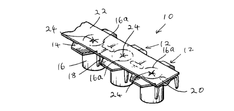
Figure 1 is an upper perspective illustration of a portion of a fastener strip
greatly enlarged, to illustrate the invention, the fasteners in this case
being Tee-
nuts;
Figure 2 is a schematic side elevational view of a fastener strip feed
mechanism such as is used in fastener setting machines, the fasteners in this
case being Tee-nuts;
Figure 3 is a schematic side elevational view of an alternate embodiment
of a fastener feed mechanism;
Figure 4 is a schematic side elevation of a portion of a collating apparatus
incorporating a punch assembly for punching hales during collating of the
fastener strips;
Figure 5 is a cut away perspective illustration of an alternate form of web
material embodying the principals of the invention;
Figure 6 is a perspective illustration partially cut away of the further
embodiment of web material;
Figure 7 is a schematic side elevational view of an alternate form of strip,
in which the recesses are in the form of depressions or dimples, are formed in
the tape in registration with recesses in the fasteners, without actual
perforations
being made through the web;
Figure 8 is a schematic top plan view of a Tee-nut feed mechanism
incorporating a one-way escapement, shown in one position, and;
s
CA 02273711 1999-06-03
Figure 9 shows the same mechanism in another position, corresponding
to a machine shut down condition.
CA 02273711 1999-06-03
DESCRIPTION OF A SPECIFIC EMBODIMENT
Before describing the various embodiments of the invention, it will be
understood that the type of fastener to which the invention relates is a
fastener
which can be driven into a work piece, usually a wooden or particle board work
piece, typically such as is used in furniture, although many other uses of
such
fasteners are known. Such fastener setting machines operate at a high rate of
repetition, so that a large number of fasteners can be set into work pieces,
over a
period of time. The fastener machines typically incorporate a setting
location, where
there is a fixed anvil, and a moveable plunger or hammer which can reciprocate
towards and away from the anvil, either downwardly or upwardly, in most cases,
and
during such driving movement the plunger or hammer will engage a fastener and
drive it towards the anvil. The work piece is placed against the anvil, so
that the
operation of the plunger drives the fastener into the work piece.
A typical example of such fastener setting machines is employed to drive
Tee-nuts into a work piece. As already explained, Tee-nuts are well known, and
comprise a planar sheet metal flange, in the centre of which there is formed a
tubular sleeve, and the interior of the sleeve is threaded to receive a bolt.
Prongs
are usually formed around the periphery of the flange. The sleeve is usually
driven
into a predrilled hole in the work piece, and the prongs are forced into the
material of
the work piece around the pre-drilled hole, with a view to holding the Tee-
nut.
Examples of such machines are shown in U.S. Letters Patent Number 5, 323,531
Inventor: Walter H. Leistner and Keith G. Bromley, dated June 28, 1994, and
U.S.
to
CA 02273711 1999-06-03
Letters Patent Number 5,606,794 inventor: Volkmar W. Leistner and also in U.S.
Letters Patent Number 5,214,843; inventor: Keith G. Bromley and Walter H.
Leistner, granted: June 1, 1993 and U.K: Letters Patent 0580907. For this
machine
Tee-nuts were formed into a strip, usually by some collating and bonding to
form of
adhesive web such as paper or the like. This strip was rolled into a wound
coil, and
the coiled strip was then placed on edge on a rotary feed table. The Tee-nuts
were
unwound from the coil, and fed into a Tee-nut feed slide. They were advanced
along the slide incrementally by means of a Tee-nut feed advance mechanism,
until
the leading Tee-nut registered with a plunger.
Reference is made to the machine shown in this patent merely by way of
example and for the sake of illustration and without, in any way, wishing to
restrict
the scope of the invention.
Such apparatus being known per se, is not illustrated over again here, since
it
is superfluous.
The Tee-nut setting machine in this patent illustrates a plunger operating in
an upward direction, with the anvil being located above the work piece and
held
stationary.
However, it will be appreciated that in many other machines the anvil is
located beneath the work piece and the plunger operates downwardly driving the
fastener downwardly.
The invention is equally applicable to both types of fastening setting
machines as well as others not discussed here.
m
CA 02273711 1999-06-03
It is, however, apparent that such apparatus of this type incorporates a feed
mechanism for advancing the Tee-nut strips, along a Tee-nut carriage or slide
path,
and it is to this aspect of a machine that the invention is directed, in one
embodiment.
As mentioned above, in such earlier machines, the Tee-nut advance
mechanism was located to one side of the feed slide. The advance mechanism
would engage the side edge of each Tee-nut and push it along the slide. The
advance mechanism usually operated at an angle, off set to one side of the
axis of
the Tee-Nut strip. Thus the sideways angled pushing movement of the advance
mechanism had a forward axial component and also a side ways component of
force. The side ways component of the feed advance mechanism tended to push
the Tee-nut strip to one side of the feed slide, and caused unnecessary and
undesirable displacement of the strip within the slide, and also set up
frictional
forces which were undesirable.
As shown in Figure 1, a fastener strip illustrating the invention is shown
generally as 10. As mentioned in this case, the fasteners are Tee-nuts and the
Tee-
nuts are shown individually by the general reference 12. As is generally well
known,
such Tee-nuts incorporate generally planar flanges 14, and tubular sleeves 16.
Prongs 18 are formed out of the flanges 14, spaced from the sleeves 16.
Although not shown, the interior of the sleeve 16 are formed in threads, and
the sleeves are open at both ends so that threaded fasteners can pass through
them. As mentioned, such Tee-nuts are well known.
12
CA 02273711 1999-06-03
In this particular case, the Tee-nuts 12 are formed with axial depressions 20,
in the flanges 14, for reasons to be described below. The invention, however,
is not
specifically limited to Tee-nuts incorporating such depressions 20, and it is,
in any
event, not specifically limited to Tee-nuts per se but is applicable to a
variety of
different fasteners, of the type which may be fed sequentially into a fastener
setting
machine.
The fasteners 12 are formed into a continuous strip by being adhesively
bonded to a continuous web or tape 22. Web or tape 22 is formed of flexible
material. It may be paper, or a paper composition, or a thermoplastic or the
like. All
of these materials have been used in the past for forming strips of fasteners
in this
way. In this particular embodiment, polyethylene type thermoplastic material
is the
preferred form of tape since it is strong enough to hold a substantial number
of Tee-
nuts and maintain them in a roll or coil. It will be noted that the web or
tape 22 is of
a reduced width in relation to the transverse dimensions of the flanges 14.
The web
22 is aligned along the central axis of the fasteners 12 and covers a
substantial
central area of the flanges 14 and also covers the top or upper ends of the
sleeves
16, which are indicated generally as 16A in phantom.
As has been previously explained, Tee-nuts strips of this general type have
been used in the past in fastener setting machines. In such machines, a Tee-
nut
feed advance mechanism was located to one side of the strip 10. The feed
mechanism engaged side edge portions of the respective flanges 14 of
successive
Tee-nuts and push them in sequence along a feed slide (see below).
13
CA 02273711 1999-06-03
In accordance with the present invention, however, the web 22 is formed with
recesses 24, which register with the upper open ends 16A of the sleeve 16. The
purpose of these recesses will become apparent from the following explanation.
However, it is noteworthy that these recesses 24 may, in some
circumstances, be preformed as actual perforations, in the web 22 before it is
applied to the fasteners. In other circumstances, the recesses or perforations
may
be formed in the web 22 during the process of collating the fasteners and
securing
them on the web, and in other cases, the recesses may be formed in the actual
advance mechanism in the Tee-nut in the fastener setting machine. While
recesses 24 are shown in this preferred embodiment as actual tears or
perforations,
there may be circumstances where a simple slit is adequate. There may be other
cases where an actual hole is punched out of the web, and in some other cases,
it
may be sufficient to stretch the web in the region of the open end 16A to form
a
recess in the form of a depression without actually breaking the web at all.
Referring now to Figure 2, this figure illustrates a strip 10, carried in a
feed
slide indicated generally as 30. The feed slide 30 is, in this case, a portion
of a
fastener setting machine, the remaining details of the fastener setting
machine are
not pertinent to this description and are omitted for the sake of clarity.
Fasteners in
the strip 10 are advanced so that the end most fastener will register with a
hammer
or plunger or piston (not shown) which is commonly incorporated in such
setting
machine and will be separated from the remainder of the strip 10, and driven
into a
work piece (not shown) by operation of such a plunger.
14
CA 02273711 1999-06-03
As mentioned above, all of this is well known and requires no separate
description of illustration.
In accordance with the invention, the advance mechanism is illustrated
generally as 32. It will be seen to comprise a power source, in this case a
cylinder
34, containing a piston 36. The piston 36 is connected to a piston rod 38
which, in
turn, is provided at its lower free end with an advance tool 40. Such a tool
40 may
be of a variety of different designs. In this particular embodiment, it
incorporates a
downwardly oriented tooth 42, the purposes of which will be described below.
The
one end of the cylinder 34 is powered by means of air through hose 44, and at
the
opposite end of the cylinder 34 there is a spring 46.
The cylinder 34, is mounted on a stub 48. Stub 48 is pivotally mounted in a
yolk 50, mounted on a fixed arm 52. The stub 48 is swingable in the yolk 50. A
return spring 54 extends between the face of the arm 52 and the free end of
the
cylinder 34.
The operation of the Figure 2 embodiment is as follows.
The Tee-nut strip 10 formed with an unbroken web 22, in this case formed of
polyethylene type thermoplastic material, although this is merely an example,
and is
in no way limiting as to the scope of the invention, is manually fed along the
slide
30, until it reaches the advance mechanism 32. At this point, the apparatus is
then
ready to commence operation. During the sequence of operations of the
apparatus,
the plunger (not shown) will cycle down and up, and as part of the timing of
such
CA 02273711 1999-06-03
apparatus, the air pressure is normally applied through hose 44 to piston 36
urging
piston 36 to compress spring 46.
During the normal cycle of operations, the air pressure on hose 44 is
momentarily released, allowing piston 46 to move under the biassing force of
spring
46, thereby extending the tool 40.
The tool 40, having a tooth 42, pierces or tears the web 22 in the region of
the upper end 16A of the sleeve 16 and thereafter, pushes the entire strip 10
along
the feed slide 30. As the machine continues to cycle, the air pressure is
alternately
applied to hose 44 and then released, causing the piston 46 to cycle to and
fro
within cylinder 46. This will draw the tool 44 backwardly, and then allow it
to move
forwardly, procuring intermittent advancing of the strip 10, and one-by-one
forming
of recesses or perforations 24 in web 22.
Eventually the first fastener in the strip will reach the plunger, at which
point
the plunger will then engage the end most fastener, and tear it away from the
rest of
the web 22 and drive it into a work piece.
Thereafter, each time the apparatus is cycled, the tool 44 will be retracted
and then advanced, thereby successively forming recesses or perforations 24 in
sequence, registering with respective fasteners 12. It will be seen that this
pushing
action takes place along the longitudinal axis of the strip 10, so that there
is no
tendency for the strip 10 to get pushed to one side of the feed slide 30.
At the same time, the formations of the recesses or perforations 24 materially
assist in the in the registering of the free end of the plunger (not shown)
with the
16
CA 02273711 1999-06-03
central sleeve in the fastener, thereby facilitating the insertion of the
individual
fasteners, one-by-one, without disturbing the rest of the fasteners in the
strip.
Referring now to Figure 3, an alternate embodiment of advance mechanism
is illustrated. In this case, the fastener strip 10 is shown supported in a
fastener
feed slide 30 of a typical fastener setting machine, as in the case of Figure
2. In this
case, the fastener advance mechanism consists of a cylinder 60, containing a
piston
62 connected to a piston rod 64.
Cylinder 60 is a mounted parallel tube, spaced above the central axis of the
strip 10, and the piston 62 and piston rod 64 reciprocate to and fro parallel
to such
axis, for the advancing of the strip.
In order to engage the fasteners in the strip and also to form recesses the
web 22, a second cylinder 66 is provided. Cylinder 66 contains a piston 68
connected to a piston rod 70. A recessing and advance tool 72 is mounted on
the
lower free end of piston rod 70.
In piston 60, piston 62 is normally urged to the left, by means of spring 74
and is moved against spring 74 by means of air pressure supplied through hose
76.
In piston 62, the piston 68 is urged upwardly by means of spring 78 and is
forced
downwardly against spring 78 by air pressure supplied through air hose 80.
Cylinder 66 is mounted on a sliding mounting plate 82, and can slide to and
fro, along the axis of piston rod 64 so as to intermittently advance the strip
10.
Tool 72 is reciprocal downwardly and upwardly so as to recess or actually
perforate the strip in the region of the opening 16A.
m
CA 02273711 1999-06-03
Thus, in the normal operating cycle of the fastener setting machine, the
piston 68 will be forced downwardly by compressed air, causing the tool 72 to
recess the web 22. Cylinder 60 will then be operated so as to advance cylinder
68,
thereby advancing the strip 10. The air pressure in cylinder 66 will then be
released,
causing the tool 72 to raise upwardly, and after that air will be supplied to
cylinder
60, causing the piston 62 to retract.
In accordance with a further embodiment of the invention, the recesses or
other formations may be formed in the web, in the process of collating the
fasteners
into a strip and attaching thereby adhesive means to the web.
Figure 4 illustrates in schematic form a portion of such a collating machine.
Number 90 relates to a collating feed slide, for collating the strip 10.
A rotary recessing wheel 92 is mounted reciprocally, so that it may move
downwardly and upwardly. The wheel 92 is provided with a plurality of recess
tools
94. Rotation of the wheel 92 will cause the tools to successively form
indentations
or perforations in the web 22. In this case, the feed mechanism of Figure 2 or
Figure 3 will not be actually required to form additional recesses or
perforations, but
it may function in essentially the same way, so that the feed mechanism
engages
the fastener by means of inter-engaging in the top end of the recess 16A. The
feed
movement of the feed mechanism is transmitted to the strip 10 along the
central axis
of the strip 10 and not from one side.
It will be understood from the foregoing that the invention is equally
applicable to a strip in which there are recesses or indentations formed in
the web in
la
CA 02273711 1999-06-03
registration with the open ends of the sleeves, as well as with strips in
which the
recesses are formed as actual tears, perforations, slits or even punched
holes.
Examples of webs showing punched holes 24A are shown in Figure 5, the web
being shown as 22A. A web shown with slits 24B is shown in Figure 6, the web
being shown as 22B.
A web formed with depressions or recesses 24, without actual perforation or
tearing of the web is shown in Figure 7 as 22C.
In accordance with further features of the invention, a feed slide escapement
mechanism may be provided in a Tee-nut feed slide, substantially as shown in
Figures 8 and 9. Figure 8 is a top plan view in schematic form looking down on
a
strip of Tee-nuts. In Figure 8, the Tee-nuts indicated generally as 100 and
the tape
or web is shown in phantom as 102. The actual details of the feed slide itself
are
not shown, since it is believed they are self evident. The Tee-nut insertion
plunger
tool is indicated generally as 104. For the purposes of this illustration, it
is shown
rotated 90°, out of its correct position. This is simply for the sake
of clarity of
explanation. The piston clearly could not operate from the actual location as
shown,
but would have to be located vertically above the Tee-nuts, substantially in
the
manner shown in the U.S. Letters Patent described above.
The movement of the Tee-nuts in both Figures 8 and 9 are from right to left.
The Tee-nut advance mechanism substantially as described in relation to, for
example, Figure 2, will be engaging the Tee-nuts from vertically above, by
placing
an insertion tool in the upper end of the central sleeve of each Tee-nut and
pushing
19
CA 02273711 1999-06-03
the strip along. In order to prevent the strip from inadvertently backing up,
an
escapement mechanism is provided, in accordance with this embodiment which
comprises a first escapement lever 106, pivoted at 108 and normally urged by
spring 110 to engage the flanges of the Tee-nuts on one side, between adjacent
Tee-nuts. A second escapement tool 112 is pivoted at 114 and engages the Tee-
nut flanges on the opposite side. The second tool is also normally urged
inwardly
by a spring 116.
It will be noted that the tools 106 and 112 are off set from one another along
the axis of the strip, by a distance equal to the length of one Tee-nut.
The tool 106 has a free end 118 which engages a limit switch 120. Limit
switch 120 may be operated to shut off supply of power, ie. compressed air, to
the
machine but is normally open to allow such supply of air to continue.
When a strip of Tee-nuts has passed both the second escapement tool 112
and the first tool 106, the tool 106 will swing inwardly and the free end 118
will swing
outwardly. This will operate limit switch 120 which will then shut off supply
of air to
the machine.
The few remaining Tee-nuts in the Tee-nut slide will then stay in place. The
fresh strip of Tee-nuts will then be inserted. The first Tee-nut will abut
against the
last Tee-nut of the previous strip and be held in position by the escapement
tool
112. As the Tee-nuts are inserted, they will spread the two escapement tools
106
and 112 apart and thereby opening limit switch 120, and allowing air to reach
the
machine for continued operation.
CA 02273711 1999-06-03
The foregoing is a description of a preferred embodiment of the invention
vhich is given here by way of example. The invention is not to be taken as
limited
o any of the specific features as described, but comprehends all such
variations
:hereof as come within the scope of the appended claims.
21