Note: Descriptions are shown in the official language in which they were submitted.
1
CONNECTOR FOR A BROKEN RUBBER-TYPE TRACK
The present invention relates to a mechanical connector used to temporarily
join two
ends of a ruptured or damaged rubber-type track of a vehicle and allow the
vehicle to
proceed to the nearest maintenance site or to a convenient location where the
replacement of the track can be undertaken.
Many modern tanks and other military vehicles, as well as some off-highway
utility
vehicles, are supported by a set of endless tracks made of a strong rubber-
type
composite material. One advantage of using rubber-type tracks is that these
tracks are
less likely to cause damages to roads or structures on which they travel, when
compared to their metallic counterparts. However, these rubber-type tracks can
be cut
transversely due to a defect in the material, wear or fatigue. A track may
also be
severed by an object on which it traveled. In the case of a military vehicle,
a track may
be severed or damaged by a mine, a nearby explosion or a projectile. In all
instances,
the affected vehicle is likely to be useless unless a repair is done on site,
even if no
section of the track is missing or extensively damaged.
An on-site replacement of a damaged track not always possible, especially if
the failure
occurred in an hostile territory or in a location which is difficult to
access. Yet, some
tanks can weight up to 60 tons and more. Replacing a track on such vehicle
requires
the presence of heavy lifting equipments that will have to be dispatched to
the location
where the vehicle is.
The object of the present invention is to allow a ruptured or damaged track to
be
temporarily repaired so that the vehicle can proceed by its own to the nearest
maintenance site or to a convenient location where the replacement of the
track can be
achieved.
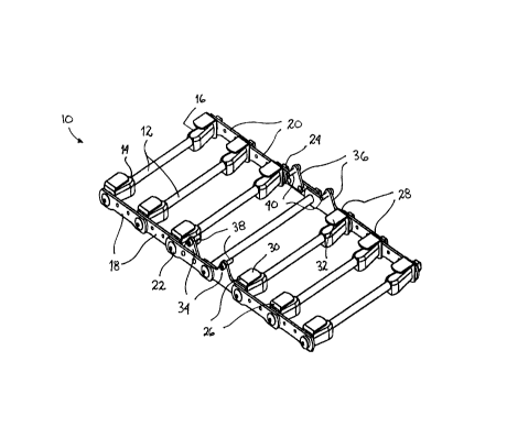
The appended figures show an example of a connector (10) according to the
present
invention. Other models are also possible, depending on the kind and the
extent of the
2
damage as well as the model of the track. The connector (10) is preferably
made of
metal.
The connector (10) comprises a plurality of parallel and spaced-apart
elongated rods
(12). Their exact number depends on the extent of the damage and the type or
the size
of the vehicle . They are to be transversely set against the exterior side of
the track. The
length of the rods (12) is equivalent to the width of the track to be
repaired. Further, the
ends of some or all rods (12) are preferably reinforced by filler blocks
(14,16) to provide
additional stiffness and to concentrate the traction forces on the sides.
The ends of the rods (12) are connected together by means of two parallel sets
of links
(18,20). The length of the links (18,20) are equivalent to the distance
between two drive
lugs on the interior side of the track. The links (18,20) of each set are
pivotally
interconnected one after the other and form an articulated linkage that is
adjacent to a
respective side edge of the track. Each link (18,20) partially overlaps an
adjacent one
and the rod (12) is inserted through a slightly larger hole made through them.
The rod
(12) is retained by a nut. The articulated linkage allows the connector (10)
to follow the
curvature of the track as the vehicle moves. Of course, another kind of
articulated
linkage may be used, such as a flexible strip of a plastic material or any
other
equivalents, as apparent to a person skilled in the art.
The connector (10) also comprises two sets of at least two L-shaped tabs
(26,28) that
are connected to or near a respective end of the rods (12). These tabs (26,28)
are
oriented inwardly. Their end section (30,32) is to be in engagement with the
interior side
of the track in order to maintain the connector (10) in place. The end
sections (30,32)
will be located between two drive lugs on the interior side of the track.
Additionally, two adjacent links (18,20) that are about the middle of each
side of the
connector (10), comprise an upright projecting flange (34,36). These flanges
(34,36)
allow one or more bolts (38,40) to be inserted through a tapped hole in the
side of a
corresponding drive lug or guide horn on the interior side of the track.
3
In use, the connector (10) is substantially centered with reference to the
crack or
damaged section in the track. By doing so, each flange (34,36) of a same side
should
be located next to a respective side of the crack or damaged section. The
bolts (38,40)
will prevent the track from bending towards the center and affect the movement
of the
track while going over the wheels and sprockets.
FIGS. 2 to 6 show the connector (10) once installed on a typical track (50).
The track
(50) is provided with drive lugs (52) and guide horns (54). As it can be
appreciated, only
the end sections (30,32) of the tabs (26,28) are in contact with the interior
side of the
track (50). Their convenient location and small size prevent them from
interfering with
the driving system of the track (50).
The present invention can be advantageously used to temporarily join two ends
of a
ruptured or damaged rubber-type track of any kind of vehicle with an internal
track
driving system, for instance off-highway utility vehicles, some snowmobiles,
tanks and
other military vehicles. It can also be used to reinforce a section of a track
that shows
signs of a possible failure before it actually happens. Moreover, the present
invention
does not need the belting of the track (50) to be punctured between the
interior and
exterior side thereof, which greatly simplifies the installation of the
connector (10).
