Note: Descriptions are shown in the official language in which they were submitted.
CA 02273961 1999-OS-31
WO 98/25744 PCTlUS97/22689
-1-
APPARATUS AND METHOD FOR CONTINUOUS FORMATION OF
COMPOSITES HAVING FILLER AND THERMOACTIVE MATERIALS,
AND PRODUCTS MADE BY THE METHOD
CROSS REFERENCE TO RELATED APPLICATION
This application claims priority from copending U. S. provisional patent
application
No. 60/032,690, filed on December 11, 1996, which is incorporated herein by
reference.
FIELD OF THE INVENTION
This invention concerns an apparatus and method for applying a hot, dry gas to
filler
and thermoactive materials, particularly cellulosic and thermoplastic
materials, in the continuous
production of composites.
BACKGROUND OF THE INVENTION
Products that combine wood materials with thermoplastic or thermoset materials
are
known. These products generally are made using batch processes, such as
processes that employ
heated platens to apply heat and a compression force to the substrate, instead
of continuous
processes.
Recently, products comprising waste plastics and waste cellulosic materials
have been.
developed) most of which are made by extrusion or injection-die methods.
Examples of patented
inventions concerning wood/plastic composite products include:
(a) Smith's U.S. Patent No. 3,995,980, which describes forming mixtures of
materials using three separate delivery systems, and thereafter extruding
products comprising the
mixture;
(b) Goforth et al.'s U.S. Patent No. 5,088,910, which describes an extrusion
process
for making synthetic wood products from recycled materials, such as low or
high density
polyethylene;
(c) Wold's U.S. Patent No. 5,435,954, which discusses a method for forming
wood-
plastic composites comprising placing mixtures of such materials in molds and
subjecting the
mixture to sufficient temperatures to cause the material to occupy the mold
and assume its shape;
and
(d) Reetz' U.S. Patents) Nos. 5,155,146 and 5,356,278, incorporated herein by
reference, which describe extrusion apparatuses and processes for processing
charges that include
expanded thermoplastic materials, such as polystyrene.
There are several disadvantages associated with the inventions discussed
above. A
principal problem associated with extrusion and injection methods is that the
particle size of the
materials used to form the composite must be fairly small. Otherwise, the
viscosity of the
CA 02273961 1999-OS-31
WO 98/25744 PCT/US97/22689
-2-
composite mixture is too high to be extruded or injection molded efficiently.
Moreover, extrusion
and injection processes are further limited by the ratio of filler materials)
such as wood, to the
thermoactive materials that can be used in the charge (i.e., the mixture of
filler material and
thermoactive material used to form the final product). This puts undesirable
constraints on the
products that can be produced.
Another problem associated with these prior processes and apparatuses
involving
heated platens is that they produce products batchwise, instead of
continuously. This substantially
reduces product throughput. For example, heated platens take too long to heat
composites
completely throughout their cross section. If the temperature of the platens
is increased too much
in an effort to speed production) the composite product may burn or scorch,
particularly at
temperatures above about 400' F. Moreover, many processes that use platen
presses require that
the platen not only be heated but also cooled during each production cycle.
This decreases
product throughput and is expensive in view of the energy required to complete
the serial heating
and cooling steps.
Steam injection processes also can be used to produce composites. However) the
initial steam heating stage is followed by continued heating to remove all of
the water applied to
the composite during the steam injection process. The combination of heating
the composite to
form products) followed by continued heating to remove water, requires a
longer period of time
and is more expensive than is desirable in a commercial process.
German Patent No. 14 53 374 (the '374 patent) describes a continuous process
for
forming composites comprising waste plastic and waste wood. A mixture of waste
plastic and
waste wood is pressed in the nip between two rollers and hot air is applied to
the substrate as it
travels around the rollers. The structural features of the apparatus described
in the '374 patent
are limiting. For example) the '374 patent teaches applying hot gas to only
one of the two major
opposed surfaces of a substrate at a time. As the substrate passes over one
roller gas is applied to
one surface; then as the substrate passes over a second roller, hot gas is
applied to the opposite
surface. There is considerable energy loss, and therefore added expense) as a
result of heated gas
being vented to the atmosphere after passing through the composite. This also
may present a
health problem in that vented gas may include volatile organic compounds
(VOCs) that present a
health risk.
Despite the inventions discussed above, there still is a need for an effective
and
efficient apparatus and method for continuously forming composite products.
SUN114IARY OF THE INVENTION
The present invention overcomes the difficulties of the prior art by providing
an
effective and efficient composite consolidation apparatus and method for
continuously forming
composite products comprising filler materials and thermoactive materials. The
apparatus and
r_._..~ ~ _ T
CA 02273961 1999-OS-31
WO 98/25744 PCT/US97/22689
-3-
method are particularly suited for forming composites comprising waste
cellulosic materials and
waste thermoplastics.
One embodiment of the consolidation apparatus includes a hot-gas distribution
system
having at least one pair of gas cells, more typically plural paired gas cells,
such as rollers or
hoods, for applying hot air to the charge. A first cell of each pair applies
gas to the charge, and
generally is referred to as an application roller. The second cell of each
pair, referred to as a
suction roller, operates at a pressure less than the application roller, i.e.,
a pressure differential
exists between the application roller and the suction roller. Certain
embodiments of the apparatus
include at least one set of baffles positioned adjacent a cell) at least one
shroud positioned about a
cell, or at least one set of baffles positioned adjacent a first cell and at
least one shroud positioned
about a second cell to eliminate or substantially reduce the amount of gas
that is vented to the
surrounding atmosphere.
The consolidation apparatus can be used in combination with other apparatuses
to
form a system. One embodiment of the system comprises: (1 ) a mixer, such as a
cyclone, for
continuous or batchwise formation of mixtures of filler material and
thermoactive material; (2)
optionally a prepress for optional densification of the mixture prior to
subsequent treatment; (3) a
consolidation apparatus having a thermal consolidation zone, and perhaps a
densifying zone) for
continuously applying hot-gas to a moving charge) the zone having at least one
pair of and
perhaps plural paired gas cells wherein a first cell of each pair applies gas
to the moving charge
and wherein a second cell of each pair operates at a pressure less than in the
first cell; and (4) a
mechanical densifying apparatus for applying a densifying pressure to the
charge downstream of
the consolidation zone. The system may further include a mat-forming apparatus
downstream of
the mixer and upstream of the consolidation zone.
The invention further comprises a method for continuously forming composites.
A
mixture is formed comprising a waste thermoactive material and a waste filler
material. The
mixture is then continuously consolidated by applying a hot, dry
noncondensable gas to the
mixture. The apparatus described above may be used to continuously apply the
gas to the
mixture) and the mixture may move continuously through a zone where the
consolidating gas is
applied. Generally, but not necessarily, the filler material comprises
cellulosic material, and the
thermoactive material is a thermoplastic material. The mixture may further
include materials
selected from the group consisting of biocides, fungicides, fire retardants,
conductive materials)
pigments, water retardants, wax-like materials, coupling agents, crosslinking
agents) and
combinations thereof.
BRIEF DESCRIPTION OF THE DRAWINGS
FIG. 1 is a flow chart illustrating certain process steps used to form
composites that
include filler materials and thermoactive materials in accordance with the
invention.
CA 02273961 1999-OS-31
WO 98/25744 PCT/US97/22689
-4-
FIG. 2 is a schematic, side elevational view illustrating a cyclone mixer for
mixing
filler and thermoactive material in accordance with the invention.
FIG. 3 is a schematic, longitudinal sectional view of an embodiment of a
continuous
consolidation and densifying apparatus in accordance with the invention.
FIG. 4 is a partial schematic longitudinal sectional view showing a portion of
a
continuous consolidation apparatus in accordance with a second embodiment of
the invention.
FIG. 5 is a schematic longitudinal sectional view showing a third embodiment
of a
continuous consolidation apparatus in accordance with the invention, including
a continuous
foraminous conveying belt.
FIG. 6 is a schematic longitudinal sectional view showing a fourth embodiment
of a
continuous consolidation apparatus in accordance with the invention having
plural hoods for
applying hot gas to a charge and removing the gas after it passes through the
charge.
DETAILED DESCRIPTION OF THE PREFERRED EMBODIMENTS
The flow chart of FIG. 1 illustrates certain process steps used to form
composite
products that include filler materials and thermoactive materials. The first
steps in the process
require selecting appropriate filler material, selecting appropriate
thermoactive material, and
thereafter forming a mixture comprising such materials. The mixture may be
used as a charge
for the continuous consolidation apparatuses illustrated in FIGS. 3-6.
Alternatively, the mixture
may be processed before being consolidated by the apparatuses of FIGS. 3-6,
such as by using a
preliminary preheating and/or pressing stages to provide an intermediate
substrate. One example
of an intermediate substrate suitable as a charge for the illustrated
continuous consolidation
apparatuses is a mat of the composite material. Mats can be formed using
conventional
apparatuses known in the art.
The apparatuses illustrated in FIGS. 3-6 continuously consolidate charges in a
consolidation stage by applying hot gas thereto using the illustrated hot-gas
distribution systems.
As used herein, "consolidates" or "consolidation, " means that the mixture of
filler and
thermoactive material is processed from a first initial density to a second,
greater density of from
about 5 pounds per cubic foot (pcfj to about 50 pcf) and more typically from
about 5 pcf to about
12 pcf. The second, greater density results, for example, as the thickness
dimension of the
charge decrease upon application of the hot gas {i.e., thermal consolidation),
and perhaps a
simultaneous densifying force (mechanical consolidation), thereto. It also
should be appreciated
that the density of the charge may be serially increased by thermal and/or
mechanical
consolidation as the charge moves through the consolidation zone.
As indicated by FIG. 1, the consolidated product may then be further
compressed to
an even greater density in a densifying stage, such as by using a conventional
press. However,
the apparatuses of FIGS. 3-5 may be designed to both compress the charge and
consolidate the
.I T
CA 02273961 1999-OS-31
WO 98/25744 PCT/LTS97/22689
-5-
charge to a greater density than could be achieved by hot gas consolidation
alone. And) each pair
of cells forming the apparatus may increase the force applied to the charge
moving through a
consolidation zone. Alternatively) the apparatuses may include (1) a first
consolidation stage
wherein the density of the charge generally increases by application of the
hot gas, and (2) a
second densifying stage wherein greater compression forces, and perhaps cooler
temperatures than
in the heating stage, are applied to the composite product to achieve the
product's final desired
density, as shown in FIG. 3.
The preferred materials, without limitation, for preparing the composite
products
comprise waste cellulosic materials and waste thermoactive materials, such as
waste plastics.
Each of these materials is described below, followed by a discussion of the
apparatuses illustrated
in the drawings.
I. MATERIALS FOR FORMING COMPOSITES
A. Filler Materials
Without limitation, a partial list of filler materials includes all natural
and synthetic
fibers, examples of which include cellulosic materials) carbon-based materials
such as carbon
fibers, glass fibers, and mixtures of these materials. A currently preferred
filler material is
cellulosic material.
The cellulosic material may be virgin wood materials, i.e., materials that
have not
been used previously to form products) such as wood chips, sawdust) cotton,
hemp) straw, or
combinations of such materials. Alternatively, the cellulosic material rnay
comprise waste
products, such as used paper, peanut shells) used cotton, used railroad ties,
fibers derived from
paper mill sludge) fibers derived from recycling mill sludge, and combinations
of such materials.
Moreover, the cellulosic material may comprise virgin materials mixed with
waste materials.
Single-layer products made in accordance with the present invention typically
include
both cellulosic materials and plastic materials where the average particle
size that ranges anywhere
from about 3/16 inch in length to about 3/4 inch in length. The strength of
the product may be
affected by the size of the particles used to form the board product, but
cellulosic and plastic
materials having particle sizes that range anywhere from about 3/16 inch in
length to about 3/4
inch in length have been found suitable for making single-layer products, or
the core portion of
multilayered board products. Multilayered products made in accordance with the
present
invention often have one or more layers that include "fines" , i.e. ,
materials having an average
particle size of less than about 3/16 inch, and more typically having a
particle size so that
approximately 80% of the particles pass through a 14 mesh size screen.
B. Thermoactive Materials
CA 02273961 1999-OS-31
WO 98/25744 PCTIUS97/22689
-6-
The filler material is mixed with a thermoactive material. "Thermoactive"
refers to
both thermoset and thermoplastic materials. Thermoplastic materials generally
are preferred
materials because waste thermoplastics can be remelted) allowing the melted
thermoplastic
material to wick along and to flow around the filler materials. The
thermoactive materials act as
S binders for the filler particles once the thermoactive materials are heated
to a temperature
sufficient to make them flow, in the case of thermoplastics, or heated to the
cure temperature in
the case of thermoset materials.
As with the filler material, the thermoactive material may be any material now
known or hereafter discovered that is useful for forming composite products.
Moreover, the
thermoactive material may be virgin, i.e., materials that have not been used
previously for any
purpose. Alternatively, the thermoactive material can be a waste material,
particularly waste
thermoplastic materials.
Examples of suitable thetmoactive materials include, but are not limited to:
polyamides and copolymers thereof; polyolefins and copolymers of polyolefins,
with particular
polyolefm examples including polyethylene, polypropylene, polybutene,
polyvinyl chloride,
acrylate derivatives, acetate derivatives, etc; polystyrene and copolymers of
polystyrene;
polycarbonates; polysulfones; polyesters; polyvinyl chloride; polyvinylidene
chloride; copolymers
of vinyl chloride and vinylidene chloride; and mixtures of these materials.
This list should not be considered an exhaustive list of thermoactive
materials that can
be used to form composites. Any readily available) relatively nontoxic
thermoactive material
which ( 1 ) can be made to flow to coat filler fibers or particles, or which
can be heated to a curing
temperature, and (2) which materials act as suitable binders for the fibrous
material, can be used.
C. Additional Materials
The composites that are produced according to the present invention are not
limited
to having only filler materials and thermoactive materials. A partial list of
additional materials
that can be used to form such composites includes preservatives, biocides,
fungicides, fire
retardants) conductive materials such as carbon black, pigments, water
retardants, wax-like
materials, coupling agents (which are used to enhance the interaction between
the filler material
and the thermoactive material), crosslinking agents, and combinations thereof.
Crosslinking agents have been found to decrease the creep observed with
composite
products made in accordance with the present invention. "Crosslinking" refers
to reactions that
occur with thermoactive materials) either intermolecularly or
intramolecularly, most typically
intramolecularly, and is distinguished from coupling agents which form bonds
between
thermoactive materials and the cellulose. See the examples provided below for
more detail
concerning crosslinkng the thermoactive materials and creep. A number of
crosslinking agents
can be used to practice the method of the present invention. For example and
without limitation)
T_ . J _ _ ... ..
CA 02273961 1999-OS-31
WO 98/25744 PCT/US97/22689
_7_
suitable crosslinking agents can be selected from the group consisting of
organic peroxides, such
as dicumyl peroxide, t-butyl peroxide, benzoyl or dibenzoyl peroxide, t-butyl
peroxybenzoate,
butyl 4,4-di-(t-butylperoxy)valerate, t-butyl curnyl peroxide) di-(2-t-
butylperoxyisopropyl)benzene,
di-2,4-dichlorobenzoylperoxide, 1,1-di-(t-butylperoxy)-3,3,5-
trimethylcyclohexane, 2,5-dimethyl-
2,5-di(t-butylperoxy)hexane, 2,5-dimethyl-2,5-di(t-butylperoxy)hexyne,
azonitriles, such as 2,2'-
azobisisobutyronitrile, azo-type derivatives, such as 2,2-azoisobutene and
triazobenzene, and other
free-radical generators, such as benzenesulfonyl azide and 1,4-dimethyl-1,4-
diphenyltetrazene, and
any combination of these crosslinking agents. Particularly suitable
crosslinking agents are
selected from the group consisting of dicumyl peroxide) t-butyl peroxide,
benzoyl or dibenzoyl
peroxide, t-butyl peroxybenzoate, and combinations thereof, with dicumyl
peroxide being a
currently preferred crosslinking agent for use in making
cellulose/thermoactive composites
according to method of the present invention.
Generally ) the crosslinking agents are mixed with the thermoactive component
or
components prior to forming mixtures comprising the thermoactive
component/crosslinking
materials and cellulose. This can be accomplished in a batch process by
forming a solution,
typically an organic solution, comprising a crosslinking agent or agents, and
then applying the
solution to the thermoactive material. Alternatively, the thermoactive
material may be immersed
in the solution comprising the crosslinking agent. In a continuous commercial
process, the
crosslinking agent likely will be applied to the thermoactive material by
atomizing liquid
crosslinking agent) or a solution comprising the crosslinking agent, and
spraying the atomized
material onto the thermoactive material.
II. MIXING FILLER AND TI~RMOACTIVE MATERIALS
Once the desired materials are selected as described above) the materials are
then
combined to form a mixture. The materials may be mixed by hand or by using a
hand actuated
mixer. However, for commercial production it is preferred to mix the materials
using a large-
capacity, continuous or batch blending apparatus that tumbles, oscillates,
shakes, or otherwise
thoroughly mixes the materials. Such apparatuses are referred to herein as
mixers.
The filler material and the thermoactive material may be mixed using a cyclone
mixing and/or heating apparatus 10 illustrated in FIG. 2. Cyclone 10 also can
be used solely as a
heating chamber for preheating a previously formed mixture of filler material
and thermoactive
material prior to the mixture being consolidated in one of the apparatuses of
FIGS. 3-6.
Cyclone IO includes a top 12, walls 14) and a bottom outlet 16. Cyclone 10
also includes a gas
supply conduit 18 which passes through wall 14. Gas conduit 18 is coupled to a
gas heater 20
and conveys hot, pressurized gas from a gas source (not illustrated) to
interior region or chamber
22 adjacent top 12 of cyclone 10. The heater heats the gas to a temperature of
from about 250°F
CA 02273961 1999-OS-31
WO 98/25744 PCT/US97/22689
_g_
to about 600°F. Gas conduit 18 is coupled to wall 14 so as to
substantially prevent the hot gas
from being vented to the atmosphere.
Cyclone 10 also includes at least one additional supply conduit 24 that passes
through
wall 14 and into the interior region 22. If the cyclone 10 is used solely to
preheat the filter
S material and thermoactive material, then the conduit 24 transports a
preformed mixture of these
materials to the interior 22 of the cyclone 10. Alternatively) if cyclone 10
is being used as both a
mixing and heating chamber, then the cyclone 10 may include a third supply
conduit 26. One of
the conduits 24 and 26 transports comminuted filler material from a filler
material storage unit
(not illustrated) to interior region 22. The other of the conduits 24 or 26
transports comminuted
thermoactive material from a thermoactive material storage unit (also not
illustrated) to interior
region 22.
The cyclone 10 is capable of performing several functions, including forming
mixtures) heating premixes of suitable mixtures, and simultaneously heating
and forming
mixtures. The mixing and/or heating functions occur in interior chamber 22.
Filler material and
thermoactive material naturally descend in a cyclonic flow path 23 towards,
and eventually
through) outlet 16 and onto a conveyor 28. Conveyor 28 conveys the filler-
thermoactive material
composition to the consolidation apparatuses illustrated in FIGS. 3-6.
From the foregoing, it will be apparent that cyclone 10, when continuously
supplied
with filler and thermoactive materials, either separately or in a premix,
provides a continuous
mixer, and perhaps heater, for the materials. As a result, a mixture or hot
mixture may be
supplied in a continuous stream, or charge, to the conveyor 28.
FIG. 2 also shows that cyclone IO may include a hot gas exhaust and recycling
conduit 30. This conduit is used to recycle gas from the interior region 22
back to gas heater 20.
Alternatively, recycling conduit 30 may be used to supply hot gas to the hot
gas distribution
systems illustrated in FIGS. 3-6.
Plural cyclones similar to cyclone 10 also may be used. For example, two or
more
cyclones 10 can be arranged adjacent each other to deliver mixtures onto a
conveyor to positions
adjacent each other across the width of a conveyor. This arrangement of plural
cyclones 10 can
be used to form mats and other charges.
Once formed and deposited on conveyor 28, the mixture should be sufficiently
permeable to a hot, dry noncondensable gas (discussed in more detail below) so
as to allow the
hot gas to circulate throughout the composite. The gas circulation can be
affected by the ratio of
the filler material to the thermoactive material. This ratio is best
determined by reference to the
attributes desired in the final product. In general, mixtures comprising a 7:3
ratio, by volume, of
filler-to-thermoactive materials to 3:7 ratio) by volume, of filler-to-
thermoactive materials can be
used. Working embodiments of the invention have made mixtures comprising
roughly a 1:1 ratio,
by volume, of filler particles and thermoactive materials, and currently it is
believed that the best
r.... _ T _ .
CA 02273961 1999-OS-31
WO 98/25744 PC'T/US97/22689
-9-
results are obtained when the filler materials comprise about 60 volume
percent or less of the
mixture.
The filler particles and plastic particles may be of different sizes and
shapes;
however, it has been found that the best results, in terms of obtaining a
thoroughly mixed
material, are obtained when the filler particles or fibers and the plastic
particles or fibers are of
roughly the same size and shape. Moreover, the larger the particle size, the
more time it takes to
melt solid thermoactive materials, and the less thoroughly covered are the
filler materials by the
thermoactive materials. Thus) powdered filler material and thermoactive
materials may be used.
The particles also generally are mixed at ambient temperatures and under
relatively dry
conditions, i.e., no added water is used during the formation of the mixture.
Additional
materials, as discussed above, may be mixed with the filler and thermoactive
materials in the
mixer.
III. CONTINUOUS CONSOLIDATION
A. Background
One primary advantage of the present invention is that it allows for the
continuous)
thermal consolidation) and if desired, mechanical densification, of mixtures
continuously supplied
as described above. Steam can be used to form the composites by thermal
consolidation.
However, dry, noncondensable gases) particularly air) are best used for the
hot-gas consolidation
process. "Dry" refers to a gas in which water is not a major component,
although "dry" does
include materials that have some water or water vapor. For example, air
generally includes some
water, the amount depending upon the location. "Dry" does not include gases
wherein a major
fraction is water, and preferably does not include materials wherein the
amount of water exceeds
the saturation point of the gas at room temperature.
"Noncondensable" refers to materials that remain in a gaseous state at ambient
conditions. One benefit of using a noncondensable gas is that the pressure and
temperature of the
gas can be independently controlled. This generally is not true for
condensable gases, such as
steam. When steam is used as the medium for applying heat to the composite,
relatively high
pressures must be used in order to maintain the gas at the desired
temperature.
There a number of gases that satisfy the stated criteria for a dry,
noncondensable gas.
Such gases include, without limitation) air, nitrogen) carbon dioxide, and
combinations of these
and other gases.
The temperature of the gas also is an important consideration. For
thermoactive
materials, the temperature generally must be high enough to "activate" the
material. With
reference to thermoplastic materials, this generally means that the
temperature is sufficiently high
to allow the thermoplastic material to become more flowable, i.e., less
viscous in nature, so that
the material can flow over and around the filler materials. For thermoses
materials) there
CA 02273961 1999-OS-31
WO 98/25744 PCT/US97/22689
-10-
generally is no precise temperature at which the material cures. Generally,
the cure rate for
thermoses materials depends upon the temperature, i. e. , there is a direct
correlation between
temperature and cure rate.
Some guidance can be provided for selecting an appropriate activation
temperature
for a given thermoplastic or thermoset material. However, it also should be
appreciated that the
precise activation temperature depends on a number of factors. A partial list
of such factors
would include the particular materials being used to form the composite) the
thickness of the
composite, the ability of the materials forming the composite to absorb heat,
and the heat capacity
or insulating properties associated with the apparatus used to thermally
consolidate) and perhaps
mechanically densify, the composite while being heated or heated and
densified.
Thermoplastic materials generally have an activation temperature in the range
of from
about 250 ° F to about 600 ° F, and more typically from about
400 ° F to about 600 ° F. For
thermoset materials, curing may begin at temperatures of as low as about
100°F, although higher
temperatures also may be used. The cure rate of thermoset materials also may
be enhanced) and
the curing temperature lowered, by using catalysts.
B. Consolidation System
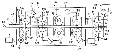
FIG. 3 illustrates an apparatus 40 for thermally consolidating and ) if
desired,
mechanically densifying, a filler-thermoactive material charge. Gas-permeable
conveyor 28
delivers to apparatus 40 continuously a charge 42 comprising a mixture of
thermoactive material
and filler, as supplied, for example, from cyclone 10. Charge 42 may be a lose
mixture of
thermoactive material and filler, known in the art as a fluff) or may be in
the form of a partially
consolidated mat formed in a pre-consolidation step, which is not shown.
Charge 42 is moved into an enclosed consolidation and heating zone 44 by
conveyor
28 through inlet 46. Zone 44 substantially reduces or prevents exposure of
people adjacent the
apparatus to volatile organic compounds (VOCs) by acting as a containment hood
to remove
fumes, fines and VOCs that may be emitted during the consolidation process.
The enclosed
consolidation zone also helps minimize heat loss from the hot gas to the
surroundings.
Consolidation zone 44 houses a plurality of hot-air distribution cells) one
embodiment
of which comprises perforated or otherwise gas-permeable rollers 50a-SOh
arranged in pairs on
opposite sides of a charge 42, for applying hot gas to and drawing hot gas at
least partially into
and perhaps through charge 42. The actual number of rollers 50 used in a
particular embodiment
is not critical, and is more likely defined by processing times, production
rate, nature and size of
the filler and thermoactive materials, and characteristics desired in the
final product. FIG. 3
illustrates eight rollers 50a-50h arranged in pairs to engage the major
opposed surfaces of charge
42. For example, roller 50a is paired with roller 50b.
T. T
- ........
CA 02273961 1999-OS-31
WO 98/25744 PCT/US97/22689
-11-
Apparatus 40 also includes at least one additional paired set of rollers 52a)
52b
located in a region exterior to zone 44 in a densifying stage of the apparatus
downstream from the
described consolidation stage. In the illustrated embodiment, hot-gas
distribution rollers SOa-SOh
consolidate charge 42 from a first density, i.e., the density of charge 42
prior to entering zone
44, to a second density. This is illustrated in FIG. 3 as a decrease in the
thickness of charge 42
from a first thickness to a second thickness in zone 44. Rollers 52a, 52b
apply positive pressure
to the charge 42 to densify the charge from the second density and thickness
to a third density and
a thickness. The third density and thickness may be those of the final
product, or there may be
an additional densifying stage (not illustrated) subsequent to the
densification stage represented by
rollers 52a, 52b.
Apparatus 40 includes a hot gas distribution system for applying hot gas to,
and into,
charge 42. The flow of gas through the system can be either counter to the
direction the charge
42 moves, or it can be in the same direction the mat moves through the
apparatus. Currently, the
preferred flow of gas through the system is indicated by arrows 54, which show
that the hot gas
flows in a direction counter to the movement of charge 42 through apparatus
40. Hot pressurized
gas from source 56 flows through checkpoint 58 in the direction of arrow 54.
Gas checkpoint 58
may include both pressure and temperature sensors to monitor the pressure and
temperature of the
gas as it flows through checkpoint 58 and into first densifying roller drum
52a.
Each pair of rollers is coupled so that one is a hot gas application roller
and the other
of the pair is a suction or evacuation (if a vacuum pump is used) roller. In
other words, a
pressure differential is created across the pair of rollers. The gas
application roller applies gas to
one major surface of the charge 42 while the evacuated roller helps draw gas
through the charge
42 and into the evacuated roller. For example, with the arrow 54 indicating
flow direction, roller
52a operates as a hot gas application roller and roller 52b operates as an
evacuated roller, thus
creating a pressure differential across the charge to help the hot gas
penetrate the charge and thus
perform its consolidation function.
Each roller SOa-50h and 52a, 52b is substantially identical and includes a
stationary
central region 60 for receiving hot gas from or directing the gas to charge
42, depending upon the
function of the roller as either an application or suction or evacuation
roller. As an application
roller, hot gas feeds into roller 52a by a hot gas conduit (not illustrated)
and into central portion
60. Central portion 60 is fluidly coupled to a hot-gas distribution region 62
which rotates on
central portion 60. External surface portion 64 of the roller is perforate) or
is otherwise rendered
gas permeable) so as to allow hot gas to flow from hot-gas distribution region
62 through surface
64 and into the charge under a pressure greater, but perhaps only slightly
greater, than ambient.
In the case of a suction or evacuation roller, gas flow is in the opposite
direction, and central
portion 60 is maintained under a negative pressure through connection to a
suction fan or vacuum
pump (not shown).
CA 02273961 1999-OS-31
WO 98/25744 PCT/(1597/22689
-I2-
The rotation of the rollers SOa-SOh and 52a,52b is synchronized. As a result,
hot gas
application region 62 of roller 52a allows hot gas to flow to charge 42 and
hot gas evacuation
region 66 of roller 52b receives gas after it flows through charge 42. In this
manner, the
application of hot gas to charge 42 through roller 52a is coupled to the gas
drawing capability of
roller 52b. Alternatively, the rollers may include an internal, stationary
baffle (not shown) that
allows hot air to be expelled through perforate rollers.
Gas exiting from roller 52b is routed into zone 44 as indicated by the gas
flow arrow
54. Prior to entering zone 44, hot gas may flow through sensor 68, which may
include a
temperature sensor, a pressure sensor, or both a pressure and a temperature
sensor. The
temperature and pressure of the hot gas can be continuously monitored at
sensor 68 prior to the
introduction of the hot gas through a second gas checkpoint 70. Gas checkpoint
70 houses a
compressor and heater (not illustrated) to ( 1 ) increase or decrease the gas
flow rate, (2) increase
or decrease the gas temperature or (3) increase the temperature and decrease
the flow rate) or (4)
increase the flow rate and decrease the temperature) or (5) increase or
decrease both the
temperature and pressure of the gas as it enters rollers SOh. Alternatively, a
charge sensor (not
shown) can be positioned between pairs of rollers to directly measure the
temperature of the
charge. The sensor could provide temperature information to pairs of cells so
that the
temperature, and perhaps flow rate of air through each pair of cells, can be
adjusted.
Whereas roller 52b is an evacuated roller in the illustrated embodiment,
roller SOh is
a gas application roller. Roller SOg, the roller coupled to roller SOh, is an
evacuation roller.
Thus, the arrangement of rollers SOg and SOh, with respect to the application
of hot air to the
opposed major surfaces of charge 42, is opposite the combination of rollers
52a and 52b. In this
manner, the application of hot air can be "pulsed" or "reversed" relative to a
particular point on
the moving charge, i.e., hot gas is applied to one major surface of charge 42
at a first position
along apparatus 40 and the charge 42 and to the second major surface of charge
42 at a second
position along apparatus 40 and the charge 42. This arrangement currently is
believed to ensure
sufficient hot gas penetration through the cross section of charge 42 to melt
or cure the
thermoactive material throughout the entire cross section, and to equalize the
temperature gradient
throughout the cross section of the charge 42.
Air passing through charge 42 and into evacuation roller SOg then feeds
through a
third gas checkpoint 72 prior to flowing through roller SOe. Again, at gas
checkpoint 72, the
pressure and temperature of the gas can be monitored to determine whether
either of these
variables must be adjusted. Gas flowing from checkpoint 72 then enters gas
application roller
SOe, which is coupled to a evacuated roller SOf. The gas drawn through charge
42 by roller SOf
is then fed through a third gas checkpoint 74. Gas flows through the remaining
rollers SOa-SOd
and through a final checkpoint 78 prior to either being (1) vented to the
atmosphere, or (2)
recycled into an upstream portion of the gas distribution system.
T. . C
CA 02273961 1999-OS-31
WO 98/25744 PCT/US97/22689
-13-
FIG. 3 also illustrates that apparatus 40 may include baffles 80. Baffles 80
generally
are arranged adjacent each of the gas rollers 50a-50h and 52a, 52b. Baffles 80
are positioned to
help prevent loss of gas as it enters or exits through surface 64 of each of
the rollers 50a-SOh, and
52a, 52b.
FIG. 4 illustrates an alternative embodiment of a baffle system that may be
used
instead of or in combination with the rollers 50a-50h and 52a, 52b. The
embodiment illustrated
in FIG. 4 shows only four rollers being housed in consolidation zone 44. It
will be understood
that the number of rollers in either of the embodiments of FIGS. 3 and 4 may
vary. The purpose
of shrouds 82 is the same as that of baffles 80, i.e., to prevent or reduce
the amount of gas
escaping from the system as the gas is applied to the charge 42. FIG. 4
illustrates that each of
the rollers includes a shroud 82 designed to substantially completely encase
the roller therein. It
also is possible to use a combination of baffles 80 and shrouds 82.
FIG. 5 illustrates still another embodiment of a continuous consolidation
apparatus
100. Again, the number of rollers illustrated may vary according to the
particular application
desired. Furthermore, structures illustrated in FIG. 5 that are similar to
those illustrated in FIG.
3 or 4 will be identified by like reference numbers.
A primary feature illustrated in FIG. 5 is the use of continuous foraminous
belts 102,
104. Foraminous belt 102 is trained around belt feed rollers 106a-106d.
Continuous foraminous
belt 104 is trained around belt feed rollers 108a-lO8d. The foraminous belts
102 and 104 are
positioned between charge 42 and the rollers 50a-50h and 52a,52b. Belts 102
and 104 have two
primary functions. First, these belts act as conveyors to convey charge 42
through zone 44.
Second, belts 102 and 104 eliminate or reduce the introduction of fines frorn
charge 42 into the
components of apparatus 100.
FIG. 6 illustrates still another alternative embodiment of a gas distribution
system for
applying a hot gas to a charge 42 in zone 44. Again, like reference numbers
will be used to
designate structures in FIG. 6 that are similar to those illustrated in FIGS.
3-5.
A primary feature illustrated in FIG. 6 is the use of an alternative gas
distribution
system for distributing hot gas to charge 42. With reference to FIGS. 3-5, the
hot-gas
distribution system comprises a series of coupled rollers for both applying
gas to and drawing gas
through charge 42. FIG. 6 illustrates paired gas distribution hoods i l0a-110h
being arranged in
paired fashion on opposite sides of charge 42. Hot-gas distribution conduit
112 feeds hot gas
through gas checkpoint 70 and into hood 100h. Hood 110h therefore is an
application hood.
Hood 110g is an evacuated hood for drawing hot gas through charge 42. As with
the previous
embodiment, hot gas flowing through the charge 42 is then fed through a gas
checkpoint 72 and
thereafter through conduit 112 into hood 110e. As a result, hood 110e is a gas
application hood,
whereas coupled hood 110f is an evacuated hood for drawing hot gas through the
charge 42.
CA 02273961 1999-OS-31
WO 98/25744 PCT/US97/22689
-14-
IV. OPERATION
The operation of the apparatus will now be described with reference to using
thermoplastics as the thermoactive material. The filler material and the
thermoplastic material are
comminuted, shredded or otherwise reduced to sizes suitable for producing
composites. A room-
s temperature or preheated mixture of the filler material and thermoactive
material is formed, such
as by using cyclone or cyclones 10. The mixture is then deposited onto
conveyor belt 28 as a
charge, which leads to the consolidation apparatuses.
The exact pressure to which the gas is pressurized before application to
charge 42 in
zone 44 depends on a number of factors, such as the materials being used, the
speed at which the
production line operates, the flow rate, the size of the particles used to
form the composite, the
thickness of the composite, etc. In general, the pressure of the hot gas as
applied to the charge
42 ranges from about 1 psi to about 50 psi. Surprisingly, it has been
determined that the melting
of thermoactive material does not prevent hot air from passing through the
mat. As a result, the
pressure of the gas generally varies from slightly above atmospheric, such as
about 0.01 psig to at
least about 10 psig above atmospheric pressure, with about 0.01 to about 2
psig being typical, and
about I psig or Iess being preferred.
As hot gas is applied to composite 42, the volume of the composite decreases
if the
thermoactive material is a thermoplastic. This is because the thermoplastic
material melts and
apparently wicks along and flows around the filler material. The mixture
thereafter appears to
collapse under its own weight to occupy less volume than the mixture
comprising solid
thermoplastic material, which is referred to herein as thermal consolidation.
This is particularly
true if thermoplastics are used as the thermoactive material because such
materials melt upon
application of hot gas. The consolidation apparatuses of FIGS. 3-6 may be
designed solely to
thermally consolidate (as opposed to a densifying) charge 42, and therefore
not compress the
composite 42 to a final product density, if the cells do not exert a
compression force on the
charge. Alternatively) the consolidation apparatuses may exert a compression
force to the
composite 42. The force applied by the final. press typically ranges from
about 100 psi to about
1,000 psi, with about 500 psi being typical.
Once the charge 42 exits outlet 48, it may be further processed to provide an
aesthetically pleasing commercial product. For example, charge 42 may be ( 1 )
sanded to provide
a smooth surface, (2) embossed with desired patterns, (3) coated with an
exterior coating so as to
provide a water-impermeable exterior, (4) covered with a paper-based exterior
coating as is
known in the art of oriented strand board) (5) laminated with veneer facings,
(6) painted, or (7)
any combination of 1-6.
Certain of the thermoactive/cellulosic composites made in accordance with the
present
invention have been surface modified in order to be painted or otherwise
surface decorated.
Methods for modifying certain thermoactive materials are disclosed in AU
9514510 and 9515286,
T_.. ~ T
CA 02273961 1999-OS-31
WO 98/25744 PCT/iJS97I22689
-15-
which are incorporated herein by reference. These methods apparently concern
modifying
polymeric materials, particularly polyethylene, such as by corona discharge
and/or flame
treatment oxidation. Flame treatment oxidation is a currently preferred method
for oxidizing the
surface of the composite product. Typically, grafting chemicals are thereafter
attached to the
oxidized polymeric material for coupling other materials, such as paint or
veneers, to the oxidized
thermoactive material.
But, there are other methods for oxidizing the surface of composite products
made in
accordance with the present invention for coupling grafting chemicals to the
product's surface.
Currently, the three most likely approaches for modifying the surface of
composite products are
as follows: (1) flame and/or corona discharge oxidation, as discussed above;
(2) photoreactions,
particularly ultraviolet irradiation in the presence of azido compounds,
including but not limited to
perfluorophenyl azides; and (3) E-beam treatment of the composite product,
perhaps
simultaneously with the application of grafting chemicals. One possible
approach will be to both
crosslink the thermoactive material of the composite product by E-beam (see
Example 7) while
simultaneously applying surface grafting chemicals to the surface of the
product.
V. EXAMPLES
The following examples are provided solely to illustrate certain particular
features of
the present invention, but the invention should not be limited to the
particular features described.
Example I
This example describes the formation of a 7/16-inch-thick composite product
having a
density of about 50 pounds/ft' and comprising about 50% waste polyethylene.
Waste
thermoplastic material, primarily polyethylene, but perhaps containing minor
fractions of other
thermoplastic materials, and wood were comminuted into flakes. A mixture was
then formed by
hand comprising about 115 grams of comminuted thermoplastic material and about
126 grams of
wood flakes having a moisture content of about 9.8 % . This mixture was then
placed in a
containment bin for thermal consolidation in a batch hot-air consolidation
apparatus that uses the
principles of the apparatuses illustrated in FIGS. 3-6, the batch apparatus
having only one cell for
applying hot air to the entire area of one surface of the mixture in the
containment bin. Hot air at
a temperature of about 400' F was applied to the mixture generally at a
pressure of less than about
1- 2 psig for a period of about 1 minute. The thermally consolidated mixture
was removed from
the consolidation apparatus and pressed to its final density in a conventional
platen press at a
pressure of about 550 psig.
Example 2
CA 02273961 1999-OS-31
WO 98/25744 PCT/US97/22689
-16-
Composite products made in accordance with the present invention may
advantageously be overlaid with a paper sheet or material, a plastic sheet or
material, or both.
For example, portions of the cellulosic material may extend upwardly from the
surface of the
board product, which is referred to herein as telegraphing. Overlaying the
board product with a
paper sheet or material, a plastic sheet or material, or both, solves problems
associated with
telegraphing. The present example describes the formation of a board product
having an
overlying layer of a thermoplastic material.
A board product was made as substantially described in Example I. A 2
millimeter-
thick sheet of low density polyethylene was then placed on each major opposing
surface of a
warm composite product after thermal consolidation. The overlaid product was
then pressed for a
period of about 2 minutes at about 550 psig in a conventional heated platen
press heated to a
temperature of about 275 ° .
Example 3
This example describes the formation of a 7/ 16-inch-thick three-layer board
product
having a core between two outer layers comprising filler and thermoplastic
fines. A first mixture
was made comprising 17 grams of thermoplastic material fines, primarily
polyethylene, and 18
grams wood fines having a moisture content of about I 1.1 % . This mixture was
formed into a
mat in a containment bin. A second mixture for the product's core was then
made comprising
about 82 grams thermoplastic material and 102 grams cellulosic wood flakes
having a moisture
content of about 12.42 % . This mixture was formed into a mat on top of the
mat situated in the
containment bin. Finally, a third layer substantially identical to the first
layer was placed on top
of the core layer in the containment bin.
Air at a temperature of about 400 ° F was applied to the mixture at a
pressure of about
I-2 psig for a period of about 1 minute. The thermally consolidated mixture
was removed from
the consolidation apparatus and pressed to its final density at a pressure of
about 550 psig using a
conventional platen press.
Example 4
This example describes the formation of a 7/ 16-inch-thick three-layer board
product
having a core between two outer layers comprising fines, the board product
being overlaid with a
plastic layer. A three-layer board product was made substantially as described
above in Example
3. A 0.002-inch-thick sheet of low density polyethylene was then placed on
each major opposing
surface of the board product after thermal consolidation. The overlaid product
was then pressed
in a conventional platen press at a pressure of about 550 psig and a
temperature of about 275 ° for
a period of about 2 minutes.
T_ . ~ _
CA 02273961 1999-OS-31
WO 98125744 PCT/US97/22689
-17-
Example 5
This example describes the formation of a 7/16 inch board having a density of
about
50 pounds/ft' and comprising about 50 % polyethylene, the board product being
surface modified
and painted. A board product was made substantially as described above in
Example 1. The
surface of the product was subjected to flame treatment to oxidize the surface
of the product
(products also have been made where the surface of the product was oxidized by
corona
discharge). A solution, such as an aqueous solution, an organic solution,
particularly alcoholic
solutions, and most typically an aqueous/organic solution (e.g.) water and
alcohol) of surface-
modifying agents, such as silanes, ketonates, zirconates, amines, chromium
compounds, etc., was
applied to the product. The surface-modified composite product was then
painted and allowed to
dry.
The adhesion of the paint to the composite product was then tested using an
Elcometer according to ASTM D4541-89 and compared to products that had not
been surface
modified. These tests showed that non-surface modified painted products fail
at the paint-product
interface, whereas the surface-modified products exhibited cohesive failure of
the product itself)
not at the paint-product interface.
Example 6
This example discusses the production of composite products having crosslinked
thermoactive materials. Waste thermoplastic material, primarily polyethylene,
and wood were
comminuted into flakes. A solution (0.5 g/ml in hexanes) comprising various
percents of
peroxide crosslinking agents) in this example dicumyl peroxide, by weight of
the thermoplastic
material as indicated below in Table I was sprayed onto the thermoplastic
material. A mixture
was then formed by hand comprising about 115 grams of the comminuted
thermoplastic material
(after soaking in the crosslinking agent solution) and about 126 grams of wood
flakes having a
moisture content of about 9.8 % . This mixture was then placed in a
containment bin for thermal
consolidation. Hot air was applied to the mixture at a pressure of about 1-2
psig and a
temperature of about 400 °F in the consolidation apparatus for a period
of about 1 minute. The
thermally consolidated mixture was removed from the consolidation apparatus
and pressed to its
final density at a pressure of about 550 psig using a conventional platen
press.
The creep rate (displacement/time) of the products made according to this
example
was then determined with respect to the gel fraction of the product, which
indicates the percent
crosslinking that occurred with the thermoactive material. The gel fraction
was determined
according to ASTM D2765-95 modified to account for the wood in the composite,
where the
wood was treated as a filler in the method. For purposes of comparison, the
creep rate for a
product made without crosslinking the thermoactive material was measured as
being 4.76 X 10~
mm/minute at a load of 50 Newtons. Loads for normal use of the product are
expected to be
CA 02273961 1999-OS-31
WO 98/25744 PCT/US97/22689
-18-
about 0.1 to about S Newtons. Composite products made according to the method
of the present
invention and having crosslinked thermoactive material had substantially
reduced creep rates as
shown by Table 1.
TABLE 1
Peroxide AdditionGel Fraction ( %a of Creep Improvement
plastic) ( % )
0 0 -
2 33 t 3 g4
6 30 ~ 4 7g
Example 7
This example further discusses the production of composite products having
crosslinked thermoactive materials. Waste thermoplastic material, primarily
polyethylene, and
wood were comminuted into flakes. A mixture was then formed by hand comprising
about 115
grams of comminuted thermoplastic material and about 126 grams of wood flakes
having a
moisture content of about 9.8 % . This mixture was then placed in a
containment bin for thermal
consolidation. Hot air was applied to the mixture at a pressure of about 1-2
psig and a
temperature of about 400°F in the consolidation apparatus for a period
of about 1 minute. The
thermally consolidated mixture was removed from the consolidation apparatus
and pressed to its
final density at a pressure of about 550 prig using a conventional platen
press.
The composite product was then subjected to electron-beam (E-beam) treatment
to
crosslink the thermoplastic material. The E-beam crosslinking was done by E-
beam Services of
Cranberry, New Jersey, but also could be done by other entities, such as the
Atomic Energy
Commission Laboratory, Whiteshell, Manitoba) Canada. The product can be
subjected to E-beam
treatment at any time following thermal consolidation, but typically is best
accomplished while the
product is still warm. Various E-beam doses in Mrads were tried. The creep
rate
(displacement/time) of the products made according to this example was then
determined with
respect to the gel fraction of the product. The gel fraction again was
determined according to
ASTM D2765-95 modified to account for the wood in the composite, where the
wood was treated
as a filler in the method.
The percent decrease in creep relative to a non-crosslinked composite product
was
determined, as summarized below in Table 2. These results are substantially
similar to the results
presented for chemically crosslinked substrates. E-beam likely will be a
preferred process for
commercial production because it can be implemented less expensively than can
chemical
crosslinking.
T_.a _ l _
CA 02273961 1999-OS-31
WO 98/25744 PCT/US97/22689
-19-
TABLE 2
E-Beam Dose Gel Fraction (% of Creep Improvement
(Mrads) plastic) (%)
0 0 _
6 40 f 4 85
16 604 g6
The present irivention has been described in accordance with preferred
embodiments.
However, it will be understood that certain substitutions and alterations may
be made thereto
IO without departing from the spirit and scope of the invention.