Language selection

Search

Patent 2273994 Summary

Third-party information liability

Some of the information on this Web page has been provided by external sources. The Government of Canada is not responsible for the accuracy, reliability or currency of the information supplied by external sources. Users wishing to rely upon this information should consult directly with the source of the information. Content provided by external sources is not subject to official languages, privacy and accessibility requirements.

Claims and Abstract availability

Any discrepancies in the text and image of the Claims and Abstract are due to differing posting times. Text of the Claims and Abstract are posted:

  • At the time the application is open to public inspection;
  • At the time of issue of the patent (grant).
(12) Patent: (11) CA 2273994
(54) English Title: NON-WOVEN INORGANIC FIBRE MAT
(54) French Title: MAT NON TISSE EN FIBRE INORGANIQUE
Status: Deemed expired
Bibliographic Data
(51) International Patent Classification (IPC):
  • B32B 5/14 (2006.01)
  • B32B 3/26 (2006.01)
  • B32B 13/02 (2006.01)
  • B32B 17/02 (2006.01)
  • C04B 28/04 (2006.01)
  • C04B 30/02 (2006.01)
  • D21H 13/40 (2006.01)
  • E04C 5/07 (2006.01)
(72) Inventors :
  • WALTERS, JOHN (United Kingdom)
  • FITZSIMONS, JOCELYN (Ireland)
(73) Owners :
  • BPB PLC (United Kingdom)
  • MOY ISOVER LIMITED (Ireland)
(71) Applicants :
  • BPB PLC (United Kingdom)
  • MOY ISOVER LIMITED (Ireland)
(74) Agent: RIDOUT & MAYBEE LLP
(74) Associate agent:
(45) Issued: 2006-05-09
(86) PCT Filing Date: 1998-01-23
(87) Open to Public Inspection: 1998-07-30
Examination requested: 2002-11-27
Availability of licence: N/A
(25) Language of filing: English

Patent Cooperation Treaty (PCT): Yes
(86) PCT Filing Number: PCT/GB1998/000203
(87) International Publication Number: WO1998/032579
(85) National Entry: 1999-05-28

(30) Application Priority Data:
Application No. Country/Territory Date
9701500.2 United Kingdom 1997-01-24

Abstracts

English Abstract


A non-woven mat (18) of inorganic fibre is disclosed having a substance which
is lower at the edges (26') of the mat than in the
remainder (28) of the mat. Apparatus for making such a mat comprises: a source
of a slurry of inorganic fibre in a liquid; a forming wire
disposed to move past the source, through which the liquid passes to deposit
the inorganic fibre on the forming wire; a mask across a part
of the width of the forming wire to hinder passage of the liquid through the
forming wire over the said part, the effectiveness of the mask
varying in the direction of movement of the forming wire past the slurry
source. A method of making the mat comprises passing a forming
wire past a slurry of inorganic fibres in a liquid while masking a part of the
width of the forming wire as it passes through the slurry, the
masking varying along the length of the forming wire as it passes through the
slurry; and urging the slurry against the forming wire and
causing the liquid to pass through the forming wire, whereby a non-woven mat
of inorganic fibre is formed having an uneven substance
(weight/unit area) in the cross direction.


French Abstract

La présente invention concerne un mat non tissé 18 en fibre inorganique dont la masse est plus légère au niveau des arêtes 26' du mat que dans le reste 28 du mat. L'appareil destiné à réaliser un tel mat comprend une source de pâte de fibre inorganique sous forme liquide; une toile de formation disposée de manière à pouvoir se déplacer au-dessus de la source et sur laquelle passe le liquide en vue de déposer la fibre inorganique sur la toile de formation; un masque, disposé sur une partie de la largeur de la toile de formation, permettant d'empêcher le passage du liquide sur la toile de formation au-delà de ladite partie, l'effet du masque variant dans le sens du déplacement de la toile de formation au-dessus de la source de pâte. Dans un procédé de fabrication du mat, on fait passer une toile de formation au-dessus d'une pâte de fibres inorganiques sous forme liquide tout en masquant une partie de la largeur de la toile de formation à mesure qu'elle passe dans la pâte, le masque variant le long de la toile de formation à mesure qu'elle passe dans la pâte; on pousse la pâte contre la toile de formation et on fait passer le liquide sur ladite toile. Ainsi, on forme un mat non tissé en fibre inorganique dont la masse est inégale (poids/unité de surface) dans le sens transversal.

Claims

Note: Claims are shown in the official language in which they were submitted.


CLAIMS

1. A non-woven mat of inorganic fibre having a weight/unit area which varies
in
the cross direction, the edge margins being of lower substance than the
remainder of the mat.

2. A method of making a non-woven mat of inorganic fibre having a weight/unit
area which varies in the cross direction, the edge margins being of lower
substance than the remainder of the mat, comprising:

passing a forming wire past a slurry of inorganic fibres in a liquid while
masking a part of the forming wire as it passes through the slurry, the said
part corresponding to an edge margin of the formed mat and the masking
varying along the length of the forming wire as it passes through the slurry;
and
urging the slurry against the forming wire and causing the said liquid to pass
through the forming wire,
whereby a non-woven mat of inorganic fibre is formed having an uneven
weight/unit area in the cross direction.

3. A method according to claim 2 in which the masking decreases in the
direction in which the forming wire passes the slurry.

4. A method according to claim 2 or 3 in which the masking is achieved by
passing the face of the forming wire remote from the slurry across a blinding
plate as it passes the slurry.

7


5. A method according to claim 4 in which the effective width of the blinding
plate decreases in the direction in which the forming wire passes the slurry.

6. Apparatus for forming a non-woven mat of inorganic fibre having a
weight/unit area which varies in the cross direction comprising:
a source of a slurry of inorganic fibre in a liquid;
a forming wire disposed to move past the source, through which, in use, the
liquid passes to deposit the inorganic fibre on the forming wire;
a mask across the part of the width of the forming wire corresponding to the
edge margins of the formed mat to hinder passage of the liquid through the
forming wire over the said part, the effectiveness of the mask varying in the
direction of movement of the forming wire past the source.

7. Apparatus according to claim 6 in which the effectiveness of the mask
decreases in the direction in which the forming wire is disposed to move.

8. Apparatus according to claim 6 or 7 in which the mask is a blinding plate
impinging the face of the forming wire remote from the source of slurry.

9. Apparatus according to any one of claims 6, 7 or 8 in which the effective
width of the blinding plate decreases in the direction in which the forming
wire passes the slurry.

10. A cementitious board having a sheet of a non-woven mat of inorganic fibre
according to claim 1 embedded immediately below at least one surface.

8


11. A cementitious board having a sheet of a non-woven mat of inorganic fibre
embedded immediately below at least one surface wherein the permeability
of the mat to cementitious slurry varies across the mat.

9

Description

Note: Descriptions are shown in the official language in which they were submitted.


CA 02273994 1999-OS-28
VNO 98/32579 PCT/GB98/00203
NON-WOVEN INORGANIC FIBRE MAT
This invention relates to a non-woven inorganic fibre mat
such as a glass fibre mat and to a method and apparatus for the
production.thereof. It also relates to the use of the mat in
building boards, such as gypsum building boards.
A particularly useful form of building board is known as
glass reinforced gypsum board (GRG). GRG board and its
manufacture is described in GB-A-2 053 779. GRG board is of
generally conventional appearance and is composed of a gypsum with
a non-woven glass mat immediately below one or both principal
surfaces. The mat is introduced into the core by vibrating the
core slurry, over- or underlain by the mat, to cause it to pass
through the mat, so that the surface layer or layers of gypsum are
integral with the core. GRG boards are stronger than conventional
boards and exhibit superior fire resistance.
In the manufacture of GRG board the need to provide
strength by employing non-woven glass fibre mat of relatively low
diameter (for example, l3~cm) fibres conflicts with the need to
ensure efficient exhaustion through the mat of air from the gypsum
slurry from which the board is formed; this is a particular
problem at the edge margins of the board where the bottom mat is
brought up and onto the upper surface of the board to define the
edges of the uncut board. Inefficient exhaustion of air in this
region can lead to voids in the edge~margins of the cut boards,
reducing the edge strength of the boards.
The problem of voids in the edge margins has been dealt
with by increasing the fibre diameter of the mat, particularly the
bottom mat (to for example l6~cm), allowing easier exhaustion of
air and penetration of gypsum slurry but reducing board strength.
However, the use of higher diameter fibres has been found to
decrease the strength of the mat. Reduction of the mat substance
(weight/unit area), which would allow the gypsum slurry to
1


CA 02273994 1999-OS-28
WO 98/32579 PCT/GB98/00203
penetrate the mat more readily, would lead to an unacceptable
reduction in board strength.
The need to allow sufficient time for the gypsum slurry
to penetrate the mat means that the line speed of the plasterboard
manufacturing line is lower than would be the case were adequate
exhaustion of air from the edge margins easier.
It has been desired to provide a GRG building board which
can be manufactured at relatively high speed, is of high strength
by virtue of using a mat of relatively low diameter fibres and the
edge margins of which have a low level of voids.
According to the invention there is provided a non-woven
mat of inorganic fibre having a substance (weight/unit area) which
varies in the cross direction.
Preferably, the edge margins are of lower substance than
the remainder of the mat.
Also, according to the invention there is provided a
method of making a non-woven mat of inorganic fibre having a
substance which varies in the cross direction comprising:
passing a forming wire past a slurry of inorganic fibres
in a liquid while masking a part of the width of the forming wire
as it passes through the slurry, the masking varying along the
length of the forming wire as it passes through the slurry; and
urging the slurry against the forming wire and causing the
said liquid to pass through the forming wire, whereby a non-woven
mat of inorganic fibre is formed having an uneven substance in the
cross direction (the cross direction is the direction on the mat
generally perpendicular to the direction in which the mat runs
through the machine, which is the machine direction).
Also according to the invention there is provided
apparatus for forming a non-woven mat of inorganic fibre having a
substance which varies in the cross direction comprising:
a source of a slurry of inorganic fibre in a liquid;
a forming wire disposed to move past the said source,
through which, in use, the said liquid passes to deposit the said
7


CA 02273994 1999-OS-28
WO 98/32579 PCT/GB98/00203
inorganic fibre on the forming wire;
a mask across a part of the width of the forming wire to
hinder passage of the said liquid through the forming wire over
the said part, the effectiveness. of the mask varying in the
direction of. movement of the forming wire past the said source.
Preferably, the mask is disposed across portion of the
forming wire corresponding to the edge margins of the formed mat.
Also preferably, the effectiveness of the mask decreases
in the direction in which the forming wire is disposed to move.
Also preferably, the mask is a blinding plate impinging
the face of the forming wire remote from the source of slurry.
Also preferably, the effective width of the blinding plate
decreases in the direction in which the forming wire passes the
slurry.
The invention also provides a cementitious board having
a sheet of a non-woven mat of inorganic fibre according to the
invention embedded immediately below at least one surface.
In a further aspect, the invention also provides a
cementitious board having a sheet of a non-woven mat of inorganic
fibre embedded immediately below at least one surface wherein the
permeability of the mat to cementitious slurry varies across the
mat.
The invention will be further described by way of example,
with reference to the drawings in which:
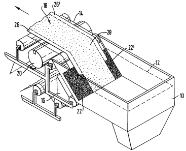
Figure 1 shows, diagrammatically, a perspective view of
an inclined wire glass fibre mat former embodying the invention;
Figure 2 shows a blinding plate for use in the apparatus
and method of the invention; and
Figure 3 shows a cross sectional view through a glass
fibre mat according to the invention.
The former shown in Figure 1 comprises a flowbox 10
containing an aqueous slurry of chopped glass fibre and
conventional additives up to the level indicated by the broken
line 12. The slurry is continuously supplied to the flowbox 10


CA 02273994 1999-OS-28
WO 98/32579 PCTlGB98/00203
from below. A continuous forming wire 14, shown transparent in
Figure 1 for clarity, passes through the flowbox 10 at angle to
the vertical and the horizontal in the direction shown by the
arrow in Figure 1. Slurry is drawn through the wire 14 and into
a suction box 16 by a conventional slurry pumping system to form
a mat 18 of. glass fibres on the wire. Shortly after leaving the
flowbox 10, the forming wire 14 carrying the mat 18 of fibres
passes over a vacuum header 20 which draws water from the mat 18.
The mat 18 on the forming wire 14 then has adhesive applied to it
and is dried and wound into a roll, in a conventional manner. The
other rollers and the frame shown in Figure 1 are conventional.
Blinding plates 22,22', shown also in Figure 2, are placed
in the flowbox 10 between the edge margins of the forming wire 14
and the suction box 16; the forming wire 14 passes across their
surface. The blinding plates 22,22' are generally rectangular
with a rectangular cut out 24,24' from their inside downstream
(relative to the forming wire 14) corner. The presence of the
blinding plates 22,22' as the wire starts to pass over the suction
box 16 prevents the passage of slurry through the forming wire 14
in the region underlain by the blinding plates and so no glass
fibres accumulate on the wire. As the wire 14 passes over the cut
outs 24,24' from the blinding plates, slurry passes through the
edge margins of the wire previously underlain by the blinding
plates and glass fibre mat accumulates. The central portion of
the forming wire 14 is not masked at all by the blinding plates
22,22', and so the glass fibre mat accumulates there throughout
the passage of the forming wire over the suction box.
The effect of this differential accumulation of glass
fibres is to make a mat having edge portions 26,26' of lower
substance (weight/unit area) than the central portion 28. This
may be seen in Figure 3. The substance of the edge margins 26,26'
of the mat can be controlled by the size of the cut-outs 24,24'
from the blinding plates 22,22' and the position of the blinding
plates relative to the suction box 16. Factors such as the
4


CA 02273994 1999-OS-28
WO 98/32579 PCT/GB98/00203
concentration of fibres in the slurry, the speed of the forming
wire and the speed with which the slurry is drawn through the
forming wire, which generally affect the deposition of fibres on
the wire and thus the substance of the mat will also affect the
substance of the edge margins 26,26' of the nut 1B.
Glass fibre mats according to the invention find
particular application in the manufacture of GRG board, described
in GB-A-2 053 779. The mat is introduced into the core by
vibrating the core slurry, over- or underlain by the mat, to cause
it to pass through the mat, so that the surface layer or layers of
gypsum are integral with the core. The lower substance of the
edge margins of the mats allow air trapped in the slurry to pass
readily through the edge margins of the mat. This avoids the
formation of undesirable voids in the edge margins of the board,
improving 'edge strength. Preferred mats for this purpose are of
13 ~cm diameter glass fibres and have a central substance of about
60 g/m~ and an edge margin substance of about 27 g/m~.
Blinding plates of the invention may be of any desired
size and shape to achieve the desired substance distribution
across the width of the mat. They may be located at one or both
edge margins of the forming wire 14, or one or more may be
disposed across the width of the wire. The blinding plates may
rest on the wire or be otherwise disposed over the wire but are
preferably under it, between it and the suction box 16.
Instead of separate blinding plates, deposition of fibres
on the forming wire can be inhibited by treating the wire itself,
for example by painting over small areas in regions of the wire.to
be masked, so that less slurry passes through the wire in these
regions, reducing the fibre deposition and thus mat substance.
Alternatively, the weave of the forming wire can be made closer in
some regions, again reducing the flow of slurry through these
regions.
The mats of the invention allow the provision of GRG type
plasterboard of improved strength especially at the edge margins.


CA 02273994 1999-OS-28
WO 98/32579 PCT/GB98/D0203
Plasterboard having the same strength edge margins as current GRG
boards can be manufactured at higher speeds than are currently
possible.
6

Representative Drawing
A single figure which represents the drawing illustrating the invention.
Administrative Status

For a clearer understanding of the status of the application/patent presented on this page, the site Disclaimer , as well as the definitions for Patent , Administrative Status , Maintenance Fee  and Payment History  should be consulted.

Administrative Status

Title Date
Forecasted Issue Date 2006-05-09
(86) PCT Filing Date 1998-01-23
(87) PCT Publication Date 1998-07-30
(85) National Entry 1999-05-28
Examination Requested 2002-11-27
(45) Issued 2006-05-09
Deemed Expired 2017-01-23

Abandonment History

Abandonment Date Reason Reinstatement Date
2006-01-23 FAILURE TO PAY APPLICATION MAINTENANCE FEE 2006-02-23

Payment History

Fee Type Anniversary Year Due Date Amount Paid Paid Date
Registration of a document - section 124 $100.00 1999-05-28
Application Fee $300.00 1999-05-28
Maintenance Fee - Application - New Act 2 2000-01-24 $100.00 1999-12-15
Maintenance Fee - Application - New Act 3 2001-01-23 $100.00 2001-01-16
Maintenance Fee - Application - New Act 4 2002-01-23 $100.00 2002-01-10
Request for Examination $400.00 2002-11-27
Maintenance Fee - Application - New Act 5 2003-01-23 $150.00 2003-01-14
Maintenance Fee - Application - New Act 6 2004-01-23 $200.00 2004-01-09
Maintenance Fee - Application - New Act 7 2005-01-24 $200.00 2005-01-12
Final Fee $300.00 2006-01-09
Reinstatement: Failure to Pay Application Maintenance Fees $200.00 2006-02-23
Maintenance Fee - Application - New Act 8 2006-01-23 $200.00 2006-02-23
Maintenance Fee - Patent - New Act 9 2007-01-23 $200.00 2006-12-18
Maintenance Fee - Patent - New Act 10 2008-01-23 $250.00 2007-12-06
Maintenance Fee - Patent - New Act 11 2009-01-23 $250.00 2008-12-29
Maintenance Fee - Patent - New Act 12 2010-01-25 $250.00 2009-12-31
Maintenance Fee - Patent - New Act 13 2011-01-24 $250.00 2011-01-18
Maintenance Fee - Patent - New Act 14 2012-01-23 $250.00 2012-01-05
Maintenance Fee - Patent - New Act 15 2013-01-23 $450.00 2012-12-13
Maintenance Fee - Patent - New Act 16 2014-01-23 $450.00 2013-12-11
Maintenance Fee - Patent - New Act 17 2015-01-23 $450.00 2015-01-02
Owners on Record

Note: Records showing the ownership history in alphabetical order.

Current Owners on Record
BPB PLC
MOY ISOVER LIMITED
Past Owners on Record
FITZSIMONS, JOCELYN
WALTERS, JOHN
Past Owners that do not appear in the "Owners on Record" listing will appear in other documentation within the application.
Documents

To view selected files, please enter reCAPTCHA code :


To view images, click a link in the Document Description column. To download the documents, select one or more checkboxes in the first column and then click the "Download Selected in PDF format (Zip Archive)" or the "Download Selected as Single PDF" button.

List of published and non-published patent-specific documents on the CPD .

If you have any difficulty accessing content, you can call the Client Service Centre at 1-866-997-1936 or send them an e-mail at CIPO Client Service Centre.


Document
Description 
Date
(yyyy-mm-dd) 
Number of pages   Size of Image (KB) 
Representative Drawing 1999-08-25 1 4
Abstract 1999-05-28 1 63
Claims 1999-05-28 2 73
Description 1999-05-28 6 258
Drawings 1999-05-28 3 61
Cover Page 1999-08-25 1 61
Representative Drawing 2004-11-03 1 18
Claims 2004-12-15 3 64
Cover Page 2006-04-06 2 64
Fees 2005-01-12 1 28
Fees 2002-01-10 1 31
Assignment 1999-05-28 3 168
PCT 1999-05-28 15 491
Correspondence 2000-02-10 6 914
Prosecution-Amendment 2002-11-27 1 39
Fees 2003-01-14 1 30
Prosecution-Amendment 2003-02-19 3 72
Fees 1999-12-15 1 52
Fees 2004-01-09 1 34
Fees 2001-01-16 1 46
Prosecution-Amendment 2004-12-06 1 32
Prosecution-Amendment 2004-12-15 5 104
Correspondence 2006-01-09 1 22
Fees 2006-02-23 1 29