Note: Descriptions are shown in the official language in which they were submitted.
CA 02274261 1999-06-07
WO 98/27001 PCT/SE97/01981
1
Reel-um
The present invention relates to a reel-up in a paper
machine in which paper is produced in a continuous web
which is reeled up in the reel-up on reeling drums to
form paper reels, each reeling drum having end portions
provided with bearing houses, said reel-up comprising
stand means including two elongate parallel stand members
each having a rail to support the reeling drum at its
bearing house; a surface winding means over which the. web
runs, arranged at the upstream ends of the stand members;
and a secondary system consisting of at least one
linearly movable secondary unit for receipt of a reeling
drum; wherein each secondary unit comprises a first
secondary body and a second secondary body said secondary
bodies being linearly movably journalled in said stand
means by means of journalling means, each secondary body
comprising an actuator for its linear movement along the
stand member and a press device arranged to press against
the bearing house of the reeling drum so that a
predetermined linear pressure is maintained in the nip
between the surface winding drum and the paper reel as it
increases in size.
A plurality of different types of reel-ups exist for
reeling a continuous paper web from a paper machine to a
paper reel. These are usually designed with two separate
systems in order to enable continuous production to be
maintained, namely a primary system for receipt of an
empty reeling drum from a pair of lowering arms upstream
of the reel-up and, when the paper web has been wound a
few turns, a secondary system which takes over the
reeling drum with the beginnings of a paper reel for
continued reeling to a finished reel-of paper.
Examples of usual types of reel-ups are those in which
the secondary system comprises either a pair of secondary
CA 02274261 1999-06-07
WO 98/27001 PCT/SE97/01981
2
arms or a pair of secondary carriages which are turned or
displaced linearly depending on the increase indiameter
of the paper reel. Reel-ups with secondary arms are
described in the following patent specifications, for
instance: US-4,143,828, US-4,283,023, US-4,175,714,
US-3,614,011 and US-5,520,354. Reel-ups with linearly
movable secondary carriages are described in the
following patent specifications, for instance:
US-4,934,619 and US-5,370,327.
Another example is a slightly different and more modern
type of reel-up which entirely lacks the primary system
described above, but which is instead provided with
double secondary units to replace said primary system. A
reel-up of this type is described in US-5,370,327.
In the present context we have chosen to use the prefix
"secondary" in the terms "secondary system", "secondary
unit", "secondary part", "secondary body", etc., even if
the reel-up does not have a primary system.
In reel-ups of the first-mentioned type, i.e. with
primary systems, reeling occurs briefly in the following
way: An empty reeling drum is transferred from a etock of
drums upstream of the reel-up to a pair of primary forks
which bring it into contact with a driven surface winding
drum over which the web runs, in order to initiate
reeling of the web. Considerable friction thus o-ccurs
between the reeling drum and the surface winding drum, so
that the reeling drum is generally first caused to rotate
at the same speed as the surface winding drum before '
coming into contact with this. The reeling drum is then
moved along the periphery of the surface winding drum, '
down to horizontal stand members where secondary units in
the form of secondary arms or secondary carriages take
over control of the reeling drum. Continued reeling to a
finished reel is achieved in that the secondary arms or
CA 02274261 1999-06-07
WO 98/27001 PCT/SE97/01981
3
secondary carriages, turning around a joint or being
~ displaced linearly along the stand members, follow the
horizontal movement of the reel caused by its increasing
size. Press devices arranged on the secondary units,
operate against bearing houses disposed on the end
portions of the reeling drum so that a desired and
adjustable linear pressure is maintained in the nip
between the surface winding drum and the paper reel as it
increases in size. For certain grades of paper the linear
pressure in the nip must be low in order to avoid
negative properties in the paper re-el. Too low a linear
pressure will result in a risk that the individual layers
in the reel will be wound too loosely. However, this
problem can be solved by connecting the reeling drum to a
central drive means with the aid of a coupling device
disposed to one end of the reeling drum since the reeling
drum no longer needs to be driven by the friction against
the surface winding drum. Central driving also allows the
linear pressure to be varied within a wider range so that
the compression of the paper web in the nip between the
paper reel and the surface winding drum can be reduced.
Reel-ups with central driving are described in the
following patent specifications, for instance:
US-4,934,619, US-5,370,327, US-5,520,354, US-5,375,790
(SE-469 071) and US-5,393,008 (SE-469 072).
When central driving is used for transferring the reeling
drum from the primary system to the secondary system, a
change of transmission must be effected between different
drive devices, which affects the linear pressure due to a
' temporary pressure increase in the said nip. To optimise
reeling, the same driving may be connected throughout the
reeling procedure from the start with an empty reeling
drum, to finished reel. To achieve this it is previously
known to use double sets of secondary carriages only,
which alternate with each other and enable omission of
the primary arms. In this way a single drive means
CA 02274261 1999-06-07
WO 98/27001 PCT/SE97/01981
4
connected to one of the carriage pairs can follow the
reeling drum throughout the reeling process to a finished
reel. A reel-up of this type is described in
US-5,370,327.
All these known reel-ups of various types, both with and
without primary systems, suffer from another considerable
common problem, namely that of undesired frictional
forces. The reason these forces constitute such a great
problem is that, as mentioned above, it is extremely
important during the reeling procedure to be able to
control the linear pressure in the nip between the
surface winding drum and the growing paperreel as
exactly as possible in order to avoid negative properties
in the paper reel, particularly when reeling soft crepe
paper such as "soft tissue" and similarly delicate paper
used for sanitary purposes, which reguiresa low linear
pressure. However, this control is made more difficult by
said frictional forces. A reliable and correct control of
the nip pressure thus requires a linear loading system
with very little friction.
Undesired frictional forces arise, inter alia, due to
friction in bearings and contact surfaces, friction in
joints of the primary and secondary arms, press devices,
etc.
Friction may also arise in the hydraulic cylinders that
move the secondary carriages. Every reel-up with
secondary carriages also has one or more rails in its
stand members, arranged to control the secondary carriage
and to minimize the friction during the to and fro
movement of the secondary carriage. The latter is
suitably effected through some form of bearings such as
roller or slide bearings.
CA 02274261 1999-06-07
WO 98/27001 PCT/SE97/01981
In a reel-up with a linear load system comprising
horizontally movable secondary units for the reeling
drum, it is the friction between the reeling drum and the
. stand rails, the stand-rail friction, which is
5 responsible for the greatest limitation in accuracy and
reliability in the control over the linear pressure in
the reel nip.
Even if the linear bearings of the secondary carriages
are designed with very little friction, the stand-rail
friction will be the same, regardless of any improvements
in the bearings of the secondary carriage, i.e. unchanged
high friction in this case, as long as the reel is
supported by the stand rail during the production phase.
Even in the case of very low frictional forces caused by
the linear bearings, the stand-rail friction will still
give relatively considerable negative effects on the
properties of the paper reel, which may also affect the
quality of the paper in other respects.
In the known reel-ups the reeling drum gives rise to at
least three different cooperating frictional forces,
namely a first friction in the bearing house caused by
rotation of the reeling drum and by movement of the
reeling drum along the stand rail as the reel increases
in size, a second friction through abutment against the
stand rail and finally a third friction in the linear
bearings of the secondary carriage.
When the reeling drum runs along the stand rail during
° production of a new paper reel, there is a not negligible
risk of obstacles in the form of foreign objects such as
' accumulated dust from the paper web, or deformities in
the stand rail or the reeling drum, having a detrimental
effect on the horizontal movement and causing temporary
oscillations in the nip pressure due to the increased
force that must be intermittently supplied to the
CA 02274261 1999-06-07
WO 98/27001 PCT/SE97/01981
6
actuators when the reeling drum encounters the obstacle,
and this may have a negative effect on the paper reel.
The uneven linear movement caused by said obstacles,
including deformations in the form of surface damage to
the stand rail, for instance, also gives rise to
unfavourable vibrations, which affect the paper reel and
in the long term may result in unnecessary wear on the
bearing house of the reeling drum, for instance, and thus
also on the coupling device for central driving of the
reeling drum.
When positioning the reeling drum along the stand as the
paperreel increases in size, the stand friction
constitutes an additional problem since it complicates
the adjustments necessary for the actuators of the
secondary unit.
The main object of the present invention is to
essentially reduce the friction problems occurring in
known reel-ups.
Another object of the invention is to provide a reel-up
having arrangements that give a linear loadsystem with
very little friction thereby enabling reliable, correct
nip-pressure control.
A further object of the invention is to provide a reel-up
in which it is possible to completely eliminate
stand-rail friction during the production of a paper
reel.
It is also an object of the invention to provide a
reel-up in which the installation of the actuators of the
secondary-units for positioning the reeling drum along
the stand in relation to the growth of the paper reel, is
facilitated.
CA 02274261 1999-06-07
WO 98/27001 PCT/SE97IOi981
7
The reel-up according to the invention is characterized
in that each secondary body, comprises a lifting means
arranged to lift the reeling drum from the associated
stand rail to a raised production level so that the
reeling drum is free from the stand rails and the load of
the paper reel and the reeling drum is taken up entirely
by the secondary bodies and transferred from them to said
stand means via said journalling means, said lifting
means comprising a top rail which has an upper support
surface and is parallel to the adjacent stand rail, and
at least one actuator to bring the support surface of the
top rail into contact with the reeling drum and effect
said lifting movement through continued substantially
vertical movement of the top rail.
The immediate advantage gained by raising the reeling
drum from the stand is reduced total friction in the
secondary system, thanks to the stand-rail friction
having been eliminated. When the load from the paper reel
is instead transferred only to the linear bearings of the
secondary carriages the friction in these increases, but
the total friction will still be lower over all since the
friction in the linear bearings is lower than in the case
of a corresponding direct contact between reeling drum
and stand rail.
Horizontal positioning of the reeling drum depending on
the growth of the paper reel will be easier to perform if
it is raised by the secondary unit and is thus free from
the stand rail since, as described above, the friction
will be lower.
The stand rails are retained for reasons of safety but
they can very well be made of lower grade steel than the
stand rails which support the reeling drum throughout the
entire reeling phase.
CA 02274261 1999-06-07
WO 98/27001 PCT/SE97/01981
8
The invention will be described in more detail in the
following with reference to the drawings.
Figure 1 is a side view of a reel-up with double
secondary units and provided with lifting means in
accordance with a first embodiment of the invention.
Figure 2 is a perspective view of the reel-up according
to Figure 1.
Figure 3 is a perspective view of an inner secondary
carriage of one secondary unit in the reel-up according
to Figures 1 and 2.
Figure 4 is a perspective view of an outer secondary part
of one secondary unit in the reel-up according to Figures
1 and 2, with a part of the box part removed.
Figure 5 is a side view of the upstream part of the
reel-up according to Figure 1 and illustrates one
operating position during the reeling process.
Figures 6 and 7 are perspective views of part of a
reel-up similar to that shown in Figure 1, but provided
with lifting means according to a second embodiment of
the invention.
Figure 8 is a cross-sectional view of a first stand
member and secondary carriage in a reel-up of the type
having a secondary unit, the secondary carriages-of which
are provided with lifting means according to a third
embodiment of the invention, with the lifting means in
inoperative position.
Figure 9 shows the same as Figure 8 but with the lifting
means in operative position.
CA 02274261 1999-06-07
WO 98/27001 PCT/SE97/01981
9
Figure 10 is a view of the secondary carriage according
to Figure 8 seen from the outside.
Figure 11 is a view of the secondary carriage according
to Figure 9 seen from the inside.
Figure 12 is a cross-sectional view of a second stand
member and secondary carriage of the reel-up according to
Figure 8, said second secondary carriage being provided
with equipment for central driving, with the lifting
means in inoperative position.
Figure 13 shows the same as Figure 12 but with the
lifting means in operative position.
Figure 14 is a side view of an outer support plate of the
second secondary carriage according to Figure 22.
Figure l5 is a side view of the lifting means of the
second secondary carriage according to Figure I2.
Figure 16 is a side view of an inner support plate of the
second secondary carriage according to Figure I2.
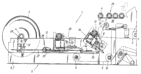
Figures 1 and 2 show schematically parts of a reel-up 1
in a paper machine in which paper is manufactured in a
continuous web 2. Paper reels 3 are reeled continuously
in the reel-up 1 on a core in the form of a reeling drum
4. The reel-up 1 comprises a stand means 5 with first and
second identical, elongate, parallel stand parts 6, 7. A
surface winding drum 8 is rotatably journalled in the
stand parts 6, 7. Over the surface winding drum 8 runs an
endless belt 9 which supports the paper web 2 coming from
a drying section, not shown, with a through-blow drying
cylinder and/or Yankee cylinder on its way to the reel-up
1. A drive motor (not shown) gives the surface winding
drum 8 a peripheral speed corresponding to that of the
CA 02274261 2003-03-20
WO 98/27001 PCT/SE97/01981
belt 9 and thus also the speed at which the paper web 2 is
fed forward. The surface winding drum may alternatively be
driven by the belt 9 which runs over a plurality of rolls
5 10 one of which, e.g. the belt turning roll 11, is then
driving. A horizontal stand rail 12 is also rigidly
mounted above each stand member 6, 7. The stand rail 12
commences with a raised portion 12a having a lowering
surface 13 for the reeling drum 4 at the upstream end of
10 the reel-up 1, seen in the feed direction of the paper web
2. The stand rails 12 are arranged slightly further apart
from each other than the width of the paper web 2. The
reeling drum 4 is provided at each end with a braking drum
14 (see Figure 3) comprising a coupling device 15 with
internal toothed rim 16 and a bearing house 17 situated
inside the coupling device 15 and provided with a groove 18
running peripherally around it for receipt of the stand
rail 12 or other control element as described below. At
the upstream end of the reel-up 1, above the surface
winding drum 8, is a stock 29 of empty reeling drums 4.
The stock 29 comprises a substantially horizontal shelf 30
on which empty reeling drums 4 rest side by side and
parallel to the surface winding drum 8, ready for use in
the reel-up 1. Actuating means (not shown) comprising
support arms and an actuator, such as a pneumatic or
hydraulic cylinder, control the gradual forward feeding of
the new reeling drums 4. An empty reeling drum 4 is
transferred from the stock 29 to the lowering surfaces 13
of the stand rails 12 by a pair of lowering arms 33 when
the growing paper reel 3 located downstream approaches a
predetermined size. The reeling drum 4 rests with its
peripheral grooves 18 on the lower surfaces 13. At the
downstream end of the reel-up 1 (see Figure 1) is a braking
station 69 with a braking arm 70 in which braking station
69 the paper reel 3 is finally retarded before being
transported along the stand rail I2 to a reel-handling
section (not shown) of the machine.
CA 02274261 1999-06-07
WO 98/27001 PCT/SE97/01981
11
The reel-up 1 comprises a secondary system which, in the
embodiment shown in Figures 1 and 2, consists of a first
secondary unit 19 and a second secondary unit 20, said
secondary units 19, 20 being reversed in relation to each
other as regards tender side and drive side. Each
secondary unit 19, 20 has a first outer secondary body 21
arranged externally on the first or second stand member
6, 7, respectively, and an inner second secondary body 22
arranged internally on the second or first stand member
7, 6, respectively. Each secondary body 21, 22 is in the
form of a carriage or sledge which is horizontally,
linearly movably journalled on a platform 23 of the stand
member 6, 7 by means of journalling means -including one
or more tracks, e.g. two parallel tracks 26 on the
platform 23, and bearings consisting of roller or sliding
bearings in the secondary carriage 22 to reduce the
friction to a minimum during its to and fro movements
along the track or tracks 26. The inner secondary
carriages 22 are also journalled in the vertical inner
sides of the stand members 6, 7 by means of similar
linear bearings, i.e. a track 26, which are rigidly
mounted on the inner side of each stand member 6, 7, and
bearings of the secondary carriage 22. The movement of
the secondary carriage 21, 22 is affected by an actuator
27, such as a pneumatic or hydraulic cylinder, attached
by one end to the secondary carriage 21, 22 and by its
other end to the stand member 6, 7. The movements along
the guide tracks 26 of the two secondary carriages 21, 22
in one and the same secondary unit 19, 20, respectively,
are synchronised with one another. Outermost on each
platform 23 cables are arranged in a cable package 28
which is flexible, allowing it to follow the to and fro
movements of the secondary carriage 21, 22.
Each secondary carriage 21, 22 of the reel-up 1 comprises
lifting means according to a first embodiment of the
present invention for lifting the reeling drum 4 from the
CA 02274261 1999-06-07
WO 98/27001 PCT/SE97/Oi981
12
stand rails 12 to a raised position so that the reeling
drum 4 is free from the stand rails 12 and the load of ,
the paper reel 3 and reeling drum 4 is entirely taken up
by the secondary carriages 21, 22 and transferred to the
stand means 5 via their journalling means.
In the embodiment of the lifting means shown in Figures
1-5 each secondary carriage 21, 22 is provided with a
pivot unit 34 for supporting cooperation with the reeling
drum 4, an actuator 41 such as a pneumatic-or hydraulic
cylinder for turning the pivot unit 34, and a level
retaining means 44 to distinctly retain the pivot unit 34
in the raised position. -
Each secondary carriage 21, 22 has a bottom plate 35 with
journalling elements 37 for pivotable journalling of the
pivot unit 34 about an axis of pivot that is parallel
with an active reeling drum 4.
Each pivot unit 34 comprises a substantially rectangular,
vertical support plate 48, a locking device 49, a press
device 50 and actuators 51, 52 for the locking device ~9
and press device 50. The press device 50 is intended to
press against the bearing house 17 of the reeling drum 4
so that a predetermined linear pressure ismaintained in
the nip between the surface winding drum 8 and the paper
reel 3 during growth of the latter. The support plate 48
is provided at its upper edge with a top rail 38 which is
parallel with the stand rail 12 and arranged to cooperate
with the reeling drum 4. An H-shaped connecting element
53 is rigidly mounted horizontally along one long side to '
the support plate 48. The locking device 49 consists of
an arc-shaped locking arm 54 hinged at its lower end to '
the above-mentioned H-shaped connecting element 53 by a
horizontal bearing pin 55 extending parallel to the
central axis of the reeling drum 4, between the two legs
of the H-shaped connecting element 53 arranged upstream.
CA 02274261 1999-06-07
WO 98/27001 PCT/SE97/0198I
I3
The actuator 51 of the locking device 49 extends between
a lower attachment point on the support plate 48 of the
pivot unit 34 and the locking arm 54 and is joined to
these in hinged manner at the ends. The free upper end of
the locking device 49 supports a roll 56 designed to
cooperate with the axis of the reeling drum 4 when the
locking device 49 is in its upper production position.
The press device 50 is situated immediately opposite the
locking device 49 in the two legs of the H-shaped
connecting element 53 and is connected therewith in
hinged manner in the same way as the locking device 49.
The press device 50 is also pivotably journalled by means
of a bearing pin 57, influenced by an actuator 52
extending between the press device 5'0 and the support
plate 48 of the pivot unit 34. The locking device 49 and
press device 50 of the two secondary carriages 21, 22
together form a gripping device for the reeling drum 4.
The reeling drum 4 is enclosed by the gripping devices
49, 50 while at the same time being freely rotatable
within these throughout the entire reeling phase of the
paper reel 3.
At the inner secondary part 22 (see Figure 3), the bottom
plate 35 is rectangular in shape and a vertical side
plate 36 is arranged along the edge of the bottom plate
nearest to the stand member 6, 7. Said journalling
element 37 comprises a beam 39 extending vertically up
from the bottom plate 35 at the end nearest the surface
winding drum 8, and a bearing pin 40 arranged at the
30 upper end of the beam 39 and forming said axis of pivot.
The pivot unit 34 is pivotable about said bearing pin 40
with the aid of the actuator 41 flexibly attached by one
end to the lower end portion of the beam 39 and by its
other end to the pivot unit 34 with the aid of guide pins
35 42, 43. Said level retaining means 44 is arranged on the
bottom plate 35 and comprises an actuator 45 and a
horizontally movable level block 46 for level retaining
CA 02274261 1999-06-07
WO 98!27001 PCT/SE97/01981
14
cooperation with a stepped level shoulder 47 on the pivot
unit 34. Since the level block 46 of the level retaining
means 44 can be set in two positions by means ofthe
actuator 45, the vertical position of the pivot unit 34
can be set in an upper production position where the ends
of the reeling drum 4 rest with their bearing house 17 on
the top rail 38 of each pivot unit 34, and a lower
position where said top rail 38 on its pivot unit 34 is
at a level below the upper edge of the stand rail 12.
When the pivot units 34 of one of the secondary units 19
or 20 is in this lower return position and the pivot
units 34 of the other secondary unit 20 or 19 is in its
upper production position, the secondary carriages 21, 22
can pass pairwise under each other. In other words, the
secondary unit 19 or 20 which has delivered a finished
paper reel 3 downstream can in other words pass below the
paper reel 3 in the process of being formed in the other
secondary unit 20, 19, respectively. The reeling--drum 4
which is in the production position is then raised from
the stand rail 12.
The outer secondary carriage 21 of each secondary unit
19, 20 is described in more detail with reference to
Figure 4, the same reference designations being used for
equivalent construction elements with respect, to the
inner secondary carriage described above. The outer
secondary carriage 21 has a bottom plate 35 which is
somewhat larger than that of the inner secondary carriage
22. Said journalling element 37 for pivotable journalling
of the pivot unit 34 about a bearing shaft comprises two
vertical beams 39, each arranged at one edge extending -
parallel to the stand member 6, 7, and two bearing pins
arranged at the upper end parts of the beams 39 and '
forming said bearing shaft for the pivot unit 34. Said
35 level retaining means 44 has its actuator 45 arranged
horizontally at right angles to the stand member 6, 7.
The pivot unit 34 comprises a stand 58 with a box-shaped
CA 02274261 1999-06-07
WO 98/27001 PCTlSE97/01981
part 59 and a platform 60 projecting therefrom. The box
- part 59 is provided with an upper horizontal plate 61 on
which parts of a means 62 for central driving of the
reeling drum 4 are arranged. Said vertical lifting plate
5 48 is here rigidly mounted to the inner vertical wall of
said box part 59 forming a part of the pivotable stand
58. Since the central drive means 62 is rigidly mounted
on the pivot unit 34 it is linearly displaceable together
with the secondary carriage 21 in a direction parallel to
10 the stand rails 12 and also pivotably together with the
pivot unit 34.
The central drive means 62 comprises a drive motor 63
firmly rigidly mounted on the platform 60, a transmission
15 box 64 rigidly mounted to the box part 59 and a power
transmission 65 arranged between them which, in the
embodiment shown, consists of a tooth belt. A rotatable
shaft 66 projects from the transmission box 64 in a
direction parallel to the reeling drum 4. A coupling
device 67 is arranged on this shaft 66 at its inner end
facing the stand member 6, 7. The coupling device 67 has
an external toothed rim 68 designed to cooperate with a
corresponding internal toothed rim 16 on the reeling drum
4. This cooperation between the two coupling devices
15, 67 is achieved by the coupling device 67 of the
central drive means 62 being displaced coaxially in
relation to the coupling device 15 until connection
occurs.
As can be seen in Figures 1 and 2, each pivot unit 34 of
- a secondary unit 19, 20 is also arranged to be turned
past the stand rails 12 up to an upper fetching position
for receipt of an empty reeling drum 4 which has been
deposited on the lowering surfaces 13 to be carried
thereafter by the top rails 38 of the pivot units 34 when
the pivot units 34 are turned back. This turning is taken
care of by the actuator 41.
CA 02274261 1999-06-07
WO 98/27001 PCT/SE97/01981
16
Unless the reeling drum 4 with the associated growing -
paper reel 3 must be lowered to the Stand rails 12 for
reasons of safety or for some other reason, it is ,
advantageous for the reeling drum 4 and paper reel 3 to
be carried by the secondary carriages 21, 22 via their
top rails 38 through the whole production phase from
empty, or substantially empty reeling drum 4 to finished
paper reel 3, after which the reeling drum 4 with
finished paper reel 3 is lowered to the stand rails 12.
Figures 6 and 7 show parts of a reel-up similar to that
described with reference to Figures 1-5, but provided
with lifting means in accordance with a second embodiment
of the invention. The lifting means comprises an actuator
41 pivotable by means of a pivot unit 34 in accordance
with the first embodiment. However, .it is provided with a
level retaining means 44 of a different type. In the
inner secondary carriage 22 shown in Figure 6, the level
retaining means 44 comprises an actuator 71 in the form
of a pneumatic or hydraulic cylinder. The cylinder 71 is
vertically rigidly mounted to the lifting plate 48 and
its piston rod 72 is directed downwards, said piston rod
72 carrying a pivotable pulley 73 for cooperationwith
the bottom plate 35. When the cylinder 71 is activated
the piston rod 72 assumes an extended position, whereupon
the pulley 73 rests against the bottom plate 35 so that
the reeling drum 4 is distinctly retained at a level
immediately above the stand rail 12 as described earlier.
In the outer secondary carriage 21 shown in Figure 7 two
vertical actuators 71 of the type described are used to
distinctly retain the reeling drum 4 at its upper level-
immediately above the stand rail 12. The vertical '
actuators 71 described may also be used to turn the pivot
unit 34 from the lower position, when the pivot unit 34
suitably rests on the bottom plate 35, to the upper
position when the top rail 38 is located at a level
CA 02274261 1999-06-07
WO 98/27001 PCT/SE97/01981
17
somewhat above the stand rails 12 so that the reeling
drum 4 is free from the latter. Alternatively the pulley
73 may be replaced by a block which is rigidly mounted to
the end of the piston rod and suitably has a rounded
support surface.
Figures 8-16 show schematically parts of a reel-up of a
different type from that described above. This type of
reel-up comprises a primary system (not shown) and a
secondary system comprising first and second secondary
carriages 78, 79 arranged on the outer sides of two
parallel stand members 80, 81 similar to those described
above. Such a reel-up is described, for instance, in
SE-B-469 071 (corresponding to US-5,375,790). Each
secondary carriage 78, 79 is linearly movably journalled
on the outside of its stand member 80, 81 by means of
journalling means comprising two parallel tracks 82 and
bearings 83, e.g. roller or sliding bearings. Each
secondary carriage 78, 79 is moved to and fro by means of
a suitable actuator (not shown).
In the embodiment of the first secondary carriage 78
shown in Figures 8-11 the lifting means according to a
third embodiment of the invention is arranged on the
inner side of a vertical support plate 84 on the first
secondary carriage 78. A press device 85 and locking
device 86 with actuators 87, 88 as described above in
connection with the reel-up according to Figures 1-5 are
located on the outside of the support plate 84. The
lifting means comprises a lifting plate 89 which is
- linearly movably journalled in the support plate 84 by
journalling means comprising two vertical tracks 90
- mounted on the support plate 84, and opposite bearings 91
which may consists of roller or sliding bearings, on the
lifting plate 89. The lifting means is also provided with
an actuator 92, such as a pneumatic or hydraulic
cylinder, for moving the lifting plate 89 up and down.
CA 02274261 1999-06-07
WO 98/27001 PCT/SE97/01981
18
The actuator 92 also has the function of level retaining
means to distinctly retain the lifting plate 89 in the
raised position when the reeling drum 4 is free from the
stand rail 94. The lifting plate 89 is provided with a
relatively short top rail 95 which is rigidly mounted to
the upper edge of the lifting plate 89 and has a flat
horizontal support surfaces which is brought into contact
with the reeling drum 4 vertically below this. The
lifting plate 89 is shaped like an inverted U, the
actuator 92 extending between its shanks.
The second secondary carriage 79, shown in more detail in
Figures 12-16, also includes means 98 for central driving
of the reeling drum 4. The secondary carriage 79-has an
inner support plate 96 by means of which the secondary
carriage 79 is linearly movably journalled to its stand
member 81 in the same way as described above for the
first secondary carriage 78. The secondary carriage 79
also has an outer support plate 97 carrying the central
drive means 98 via a stand 99, as well as a locking
device 100 and a press device 101 with associated
actuators 102, 103 of the same type as described above
for the first secondary carriage 78. The lifting means is
arranged between the inner and outer support plates
96, 97 and comprises a lifting plate 104 which is
linearly movably journalled to the inner support plate 96
by journalling means comprising two vertical tracks 105
rigidly mounted on the inner support plate 96 and
opposite, cooperating bearings 106, consisting of roller
or sliding bearings, on the lifting plate 104. The
lifting means is also provided with an actuator 107, such
as a pneumatic or hydraulic cylinder, for moving the
lifting'plate 104 up and down, whereupon the actuator 107
also functions as level retaining means to distinctly
retain the lifting plate 104 in the raised position when
the reeling drum 4 is free from the stand rail 108. The
lifting plate carries a relatively short top rail 110
CA 02274261 1999-06-07
WO 98/27001 PCT/SE97/01981
19
which is rigidly mounted to the upper edge of the lifting
plate 104 and has a flat horizontal support surface which
is brought into contact with the reeling drum 4
vertically below this. As is more easily seen in Figures
15 and 16, the lifting plate 104 and the inner support
plate 96 are provided with apertures 111, 112 for
mounting of the actuator 107, the lower end thereof being
attached to the inner support plate 96 and the upper end
to the lifting plate 104 by means of lower and upper
attachments 113, 114. The outer support plate 97 is
vertically linearly movably journalled on the lifting
plate 104 by means of journalling means comprising
vertical guide tracks 115 mounted on the lifting plate
104, and opposing bearings 116, consisting of roller or
sliding bearings, on the outer support plate 97. A stop
(not shown) is arranged to fix the outer support plate 97
in a lower position when the reeling drum 4 rests on the
rails 94, 108, in which case the outer support plate 97
is situated with its upper edge a predetermined distance
from the reeling drum 4. The lifting plate 104 is
provided at its lower end and on its outer side, with a
boss-shaped follower 117 for cooperation with the outer
support plate 97 so that a small space is formed between
the follower 117 and the lower edge of the outer support
plate 97 when the outer support plate 97 is in said lower
position and when the reeling drum 4 rests on the stand
rail 108. This space is as great as the space between the
top rail 110 of the lifting plate 104 and the reeling
drum 4. When the actuator 107 is activated the lifting
plate 104 is moved upwards and will then lift the reeling
drum 4 at the same time as the follower 1I7 is brought
into engagement with the outer support plate 97 and lifts
' this a corresponding distance so that the central axis of
the central drive means 98 is kept in line with the
.central axis of the reeling drum 4.
CA 02274261 1999-06-07
WO 98/27001 PCT/SE97/0i981
In a reel-up in particular with secondary carriages
according to Figures 1-7, embodiments of the lifting
means other than those shown here can be used. The
lifting means may, for instance, comprise a wedge-shaped
5 level block which is horizontally displaceable in order
to raise and lower the pivot unit, or a pivotable
eccentric device, the eccentric peripheral surface of
which raises and lowers the pivot unit by means-of
turning, or a suitable screw means.
The distance between the stand rails 12 and the reeling
drum 4 in its said raised production position is the same
at both stand rails I2 and is at least 1 mm, preferably
at least 2 mm. '
It is preferred that the support surface of the top rail
38 is flat and horizontal.