Note: Descriptions are shown in the official language in which they were submitted.
CA 02274341 2007-02-06
1
FUEL LINE ARRANGEMENT Flti LPC SYS'IZM. AND METHOD
Field of theInvention
This invention relates to liquefied petroleum gas fiue1 injection
systems and more particularly to fuel line arrangementh and cooling methods
for
such systems.
Background of the Invention
Liquefied petroleum gas ("LPG") fuel supply systoms are known, for
example as shown in applicants U.S. Patent Nos. 5,291,869; 5,325.838; and
5,423,303. Such systems typically include a number of specialized fuel
injectors
which receive fuel from a hig,h pressure tank. A fuel rail conncctcd in linc
with a
series of injectors is often employed to deliver fuel to the injectors. In
many
systems, uninjected fuel is rcturned to the fuel tank. This is genetally done
to keep
the supply fuel as cool as possible, particularly where it is intend.od to
injcct LPG in
liquid rather than gaseous form.
In LPG systems where uninjected fuel is returned to the fuel tanlc,
separate supply and return fuel lines are eraployed in the art. More than one
supply
line and more than one return line are also often employed, with a separatc
supply
and return line for each bank of fuel injectors.
TheriC we mariy problems associated witlt havuig multiple supply and
retum lines in LPG systems. One is that the fuel in the supply line is exposcd
to heat
from the engine and other sources, which causes undcsirable vaporization.
Another
problem is that all of the lines must be very strong, typically having large
wall
thickness and requiring reinforcement, in order to withstand the very high
pressures
(sometimes over 300 psi) that can occur in LPG systenu. Other problcms invo2ve
safety and environmental concerns. Due to thc large numbcr of hosc connections
and the latge amount of exposed fuel linc, the possibility of fuel leaks is
substagtially increased.
What has been needed is a fuel line ariangcment for LPG systems,
and a method, that avoid these problems.
CA 02274341 1999-06-11
2
Summary of the Invention
According to the present invention, a method of cooling supply fuel
in an LPG system, and a fuel line arrangement for an LPG system, are provided.
In the method of the present invention, an LPG system having a
plurality of fuel injectors, a fuel supply and a fuel return line, and a fuel
tank, is
provided. The supply and return lines are communicated with the tank, and the
supply line is communicated with each of the fuel injectors. The supply line
is
positioned within the return line so that return fuel substantially surrounds
the supply
line. Under certain conditions, return fuel in the fuel return line is
vaporized,
thereby cooling supply fuel in the supply line.
In the apparatus, a fuel line arrangement for an LPG system includes
a fuel supply line for connection between the fuel tank and a plurality of
fuel
injectors and a fuel return line for connection to the tank and for returning
a portion
of the supply fuel from the supply line to the tank. The supply line is
positioned
within the return line so that the return fuel substantially surrounds the
supply line.
A mechanism is provided for vaporizing LPG returning to the tank through the
return line, thereby cooling supply fuel.
These and other advantages and features of novelty which
characterize the invention are pointed out with particularity in the claims
annexed
hereto. However, for a better understanding of the invention and its
advantages,
reference should be made to the drawings which form a further part hereof, and
to
the accompanying descriptive matter in which there is illustrated and
described a
preferred embodiment of the invention.
Brief Description of the Figures
Figure 1 is a schematic diagram of a system according to the present
invention;
Figure 2 is a cross-sectional view of a fuel line arrangement and a
connection according to the present invention;
Figure 3 is a cross-sectional view of a Y-connector according to the
present invention; and
Figures 4A and 4B are plan and cross-sectional views, respectively,
of a bushing according to the present invention.
Detailed Description of the Preferred Embodiment
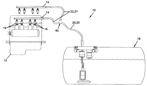
Referring now to the drawings, wherein like numerals designate like
parts throughout the figures, a fuel supply system 10 for providing LPG to an
internal combustion engine 12 is shown.
CA 02274341 1999-06-11
3
System 10 includes two fuel rails 14 which deliver fuel to a plurality
of fuel injectors 16. Although fuel rails are shown in the preferred
embodiment, they
are not necessary within the principles of the invention; for example,
separate supply
lines branching from a main supply line could deliver fuel to each injector in
parallel. Return fuel also need not come from each of the fuel injectors as is
the case
in the applicant's patented system incorporated above by reference.
Supply fuel from tank 18 is delivered to injectors 16 via primary 20
and secondary 22 supply lines, and return fuel is delivered back to tank 18
via
secondary 27 and primary 25 return lines. A Y-connector 40, further discussed
below, splits the primary lines 20, 25 into secondary lines 22, 27.
The preferred fuel line arrangement is shown in Figures 2 and 3.
Primary supply line 20 is positioned completely within primary return line 25,
as is
secondary supply line 22 with respect to secondary return line 27. Supply
lines 20,
22 are not restrained axially within return lines 25, 27, but rather are only
restrained
by the inner walls of return lines 25, 27 along the length of the lines,
thereby creating
a generally concentric arrangement. The annular flow area of return lines 25,
27 is
preferably about two or more times the annular flow area of the respective
supply
lines 20, 22 along the entire length of lines, including within fittings and
connectors.
Lines 20, 22, 25, 27 are made of nylon, but a high heat transfer metal such as
aluminum may be preferable. Wall thicknesses are.025 and.035 inches for
primary
20 and secondary 22 supply lines respectively, and .180 and .210 inches for
primary
and secondary 27 return lines respectively. These relatively thin wall
thicknesses
for supply lines is sufficient because the pressure differential across the
wall is only
on the order of 30-70 psi as compared to the over 300 psi differential that
would
25 occur if supply lines were not contained within return lines. Arrangements
other
than the concentric fuel line arrangement shown and described herein could be
employed within the principles of the invention, where the supply line is
positioned
within the return line so that return fuel substantially surrounds the supply
line.
The concentric fuel line arrangement can be surrounded with an
appropriate insulator in high heat areas such as the engine, transmission and
exhaust,
in order to minimize heat absorption. The preferred insulation is closed-cell
foam
rubber 1/4 to 3/4 inch thick.
The return fuel surrounding supply lines 20, 22 vaporizes or
evaporates through thermodynamic phase change processes that are fully
described
in the applicant's patents incorporated by reference. As the temperature of
return
fuel increases, or its pressure decreases, the LPG tends to vaporize from a
liquid to a
gaseous state. This phase change extracts heat from supply fuel through the
walls of
CA 02274341 1999-06-11
4
supply line hoses 20, 22. Supply fuel is consequently cooled, thereby helping
to
maintain it in a liquid state prior to injection into the engine.
Figures 2 and 3 show the fuel line connections. Return hoses 25, 27
are connected to steel return fittings 26, 28 with steel collar 29, as shown
in Figure 3.
Return fittings 26, 28 are held in place by locking clips 31 bracing against
retaining
flanges 30, and can be further held in place by a device that resists
rotation. 0-rings
32 seal against the outer surface of return fittings 26, 28, and are held in
place by
pressed in sleeves 33. Supply hoses 20, 22 extend through bushings 50 and are
sealed by 0-rings 54. In the Y-connector shown in Figure 3, the surrounding
structure cast into the part holds the various components described above in
place;
end caps 49 additionally retain locking clips 31. In the fuel rail connection
shown in
Figure 2, an aluminum fitting 35, connected to fuel rail 14 by threads 36,
provides
the structure which primarily holds in place the various components. Supply
hose
adapter 38, a plastic part press fit into fuel rail supply channel 60, also
surrounds
annular body 53 of bushing 50 and 0-ring 54. Fitting 35 is sealed to fuel rail
14 via
0-rings 37. The tank connection is the same as the primary Y connection. Any
other necessary connections can be the same or similar to those shown in
Figures 2
and 3.
A novel aspect of the concentric fuel line connection is bushing 50.
Bushing 50, best shown in Figures 4A and B, has circumferencially spaced
fingers
that serve two important functions. First, when supply lines 20, 22 are being
inserted, ramped surfaces 51 guide the hose into annular body 53 to assure
proper
alignment and sealing. Second, the space between fingers 52 serves as a flow
path
for return fuel: in the Y-connector shown in Figure 3, they permit flow
between
return lines 27, 28 and connecting return passages 46; and in the fuel rail
connection
shown in Figure 2, they permit flow between fuel rail return channel 61 and
secondary return line 27. Bushing 50 is made of a plastic compatible with LPB,
such as nylon or acetal.
Another novel aspect of the present invention is Y-connector 40,
which splits primary fuel lines 20, 25 into two secondary lines 22, 27.
Primary
supply hose 20 communicates with secondary supply hoses 22 via supply passage
42
and two secondary supply passages 43. Secondary return lines 27 communicate
with
primary return line 25 via connecting return passages 46; cross-connecting
passage
47 also facilitates flow between connecting return passages 46. Y-connector is
cast
preferably from aluminum, but could also be cast from other metals such as
brass.
Internal webs (not shown) in connecting return 46 passages support internal Y
48. A
connector such as 40 could be used in places other than at the fuel rails,
wherever it
CA 02274341 1999-06-11
is desirable to split a concentric fuel line arrangement into two or more
concentric
lines, as for example into separate lines for individual tanks or fuel
injectors.
It should be understood that the present invention is not limited to the
preferred embodiment discussed above, which is illustrative only. Changes may
be
5 made in detail, especially in matters of shape, size, arrangement of parts,
and
material components within the principles of the invention, to the full extent
indicated by the broad general meanings of the terms in which the appended
claims
are expressed.