Note: Descriptions are shown in the official language in which they were submitted.
CA 02274398 1999-06-11
"SINGLE BREATH INDUCTION ANESTHESIA APPARATUS"
The present invention relates to improvements in
the field of anesthesia. More particularly, the invention
s is concerned with a single breath induction anesthesia
apparatus.
When it is necessary to anesthetise a patient,
it is highly desirable to pre-oxygenate the patient prior
~o to inducing anesthesia in order to saturate the patient's
blood with oxygen so as to increase the safety of a
subsequent ventilation and endotracheal intubation. Pre-
oxygenation of the patient is carried out by using a
parallel oxygen supply and breathing system connected by
means of a conduit to the anesthesia face mask affixed to
the patient. Due to the complexity of such a technique,
pre-oxygenation is often skipped.
In the case where pre-oxygenation is effected,
2o while the patient is being pre-oxygenated, the doctor
usually closes with his fingers the distal end of the
conduit connected to an anesthesia machine and adapted to
deliver an oxygen/anesthesia gas mixture to the patient,
during operation of the anesthesia machine, so as to
2s permit the anesthesia gas in the mixture to reach a preset
concentration sufficient to induce anesthesia of the
patient with a single breath. Since it is impossible to
close with one's fingers the anesthesia gas conduit in a
gas-tight manner, leaks of anesthesia gas often occur,
3o which pollute the operating room. When the desired
concentration of anesthesia gas has been reached, the
oxygen conduit is disconnected from the anesthesia face
mask and the anesthesia gas conduit connected thereto.
During this disconnection and connection of conduits,
3s important leaks of anesthesia gas occur, which not only
further pollute the operating room but lower the
- 1 -
CA 02274398 1999-06-11
concentration of anesthesia gas in the oxygen/anesthesia
gas mixture delivered to the patient so that single breath
induction anesthesia of the patient is considerably slowed
down.
It is therefore an object of the present
invention to overcome the above drawbacks and to provide a
single breath induction anesthesia apparatus which readily
permits pre-oxygenation of the patient and single breath
~o induction anesthesia thereof, without causing pollution of
an operating room with anesthesia gas.
In accordance with the invention, there is thus
provided a single breath induction anesthesia apparatus
for anesthetising a patient, comprising a gas delivery
system for delivering at least one gas to the patient, an
oxygen supply system for providing oxygen and an
oxygen/anesthesia gas supply system for mixing oxygen and
at least one anesthesia gas at a preset optimum ratio
zo sufficient to induce anesthesia of the patient with a
single breath, thereby providing an oxygen/anesthesia gas
mixture. The apparatus of the invention further includes a
valve for providing selective gas flow communication
between the oxygen supply system and the gas delivery
z5 system or between the oxygen/anesthesia gas supply system
. and the gas delivery system. The valve is operable for
first establishing gas flow communication between the
oxygen delivery system and the gas delivery system to
deliver oxygen to the patient and permit pre-oxygenation
3o thereof, while inhibiting gas flow communication between
the oxygen/anesthesia gas supply system and the gas
delivery system to allow the oxygen/anesthesia gas mixture
to reach the preset optimum ratio, and thereafter
establishing gas flow communication between the
35 oxygen/anesthesia gas supply system and the gas delivery
system to deliver the oxygen/anesthesia gas mixture to the
- 2 -
CA 02274398 1999-06-11
patient and permit single breath induction anesthesia
thereof, while inhibiting gas flow communication between
the oxygen supply system and the gas delivery system.
s According to a preferred embodiment, the valve
comprises a valve body having a first port in gas flow
communication with the oxygen supply system, a second port
in gas flow communication with the oxygen/anesthesia gas
supply system and a third port in gas flow communication
~o with the gas delivery system, and a valve member within
the valve body. The valve member is movable between a
first position whereat the first port is in gas flow
communication with the third port and the second port is
closed, and a second position whereat the first port is
~5 closed and the second port is in gas flow communication
with the third port. Preferably, the valve body has first,
second and third tubular branches, the first, second and
third ports being defined at respective proximal ends of
the first, second and third tubular branches,
zo respectively.
According to another preferred embodiment, the
second and third ports are disposed along a first axis and
the first port is disposed along a second axis extending
z5 transversely of the first axis. The valve body has a
generally T-shaped configuration with the second and third
tubular branches extending along the first axis and the
first tubular branch extending along the second axis. In
such an embodiment, the valve member preferably has a T-
3o shaped gas passage formed therein.
According to a further preferred embodiment, the
valve includes stop means for arresting the movement of
the valve member at each of the first and second
35 positions. Preferably, the stop means each comprise
- 3 -
CA 02274398 1999-06-11
cooperating abutment means disposed on the valve member
and the valve body.
According to yet another preferred embodiment,
s the first tubular branch is provided with oxygen vent
means for venting excess oxygen when the valve member is
in the second position. Preferably, the oxygen vent means
comprise an oxygen vent orifice formed in the wall of the
first tubular branch and a removable closure member for
~o selectively closing the oxygen vent orifice when the valve
member is in the first position or opening the oxygen vent
orifice when the valve member is in the second position.
Due to the provision of the aforesaid valve
t5 enabling selective gas flow communication between the
oxygen supply system and the gas delivery system or
between the oxygen/anesthesia gas supply system and the
gas delivery system, the apparatus according to the
invention permits pre-oxygenation of a patient and single
2o breath induction anesthesia thereof, without causing
pollution of the operating room with anesthesia gas.
The present invention therefore also provides,
in another aspect thereof, a single breath induction
zs anesthesia valve adapted to be used with a gas delivery
system for delivering at least one gas to a patient, with
an oxygen supply system for providing oxygen and with an
oxygen/anesthesia gas supply system for providing a gas
mixture containing oxygen and at least one anesthesia gas
3o at a preset optimum ratio sufficient to induce anesthesia
of the patient with a single breath. The valve according
to the invention comprises a valve body having a first
port adapted to be in gas flow communication with the
oxygen supply system, a second port adapted to be in gas
35 flow communication with the oxygen/anesthesia gas supply
system and a third port adapted to be in gas flow
- 4 -
CA 02274398 1999-06-11
communication with the gas delivery system, and a valve
member within the valve body. The valve member is movable
between a first position whereat the first port is in gas
flow communication with the third and the second port is
s closed, whereby to permit delivery of oxygen to the
patient and pre-oxygenation thereof, and a second position
whereat the first port is closed and the second port is in
gas flow communication with the third port, whereby to
permit delivery of the oxygen/anesthesia gas mixture to
~o the patient and single breath induction anesthesia
thereof.
Further features and advantages of the invention
will become more readily apparent from the following
15 description of a preferred embodiment thereof as
illustrated by way of example in the accompanying
drawings, in which:
Figure 1 schematically illustrates a single
zo breath induction anesthesia apparatus according to a
preferred embodiment of the invention;
Figure 2 is a fragmentary side view of the
apparatus illustrated in Fig. 1, showing the valve with
z5 the valve member thereof in a first position; and
Figure 3 is another fragmentary side view of the
apparatus illustrated in Fig. 1, showing the valve with
the valve member thereof in a second position.
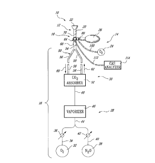
Referring first to Fig. 1, there is illustrated
a single breath induction anesthesia apparatus which is
generally designated by reference numeral 10 and seen to
comprise a gas delivery system 12 for delivering at least
3s one gas to a patient (not shown), an oxygen supply system
14, an oxygen/anesthesia gas supply system 16 and a valve
CA 02274398 1999-06-11
18 for providing selective gas flow communication between
the oxygen supply system 14 and the gas delivery system 12
or between the oxygen/anesthesia gas supply system 16 and
the gas delivery system 12. The gas delivery system 12
s comprises a connector tube 20 and an anesthesia face mask
22 connected thereto. The oxygen supply system 14
comprises an oxygen source 24 and an oxygen bag 26
defining an oxygen reservoir. The oxygen/anesthesia gas
supply system 16, on the other hand, includes an
~o oxygen/anesthesia gas source circuit 28 and a breathing
circuit 30 in gas flow communication with one another.
The oxygen/anesthesia gas source circuit 28
comprises an oxygen source 32 for supplying oxygen which
~5 flows through line 34 provided with a valve 36 and a flow-
meter (not shown), a nitrous oxide source 38 for supplying
nitrous oxide which flows through line 40 provided with a
valve 42 and a flow-meter (not shown), lines 34 and 40
merging into line 44, and a vaporizer 46 which is
2o connected to line 44 and mixes the oxygen and nitrous
oxide with an anesthesia gas such as sevoflurane at a
preset optimum ratio sufficient to induce anesthesia of
the patient with a single breath. The nitrous oxide is
another anesthesia gas which increases the anesthesia
2s effect of sevoflurane. The vaporizer is controlled so as
to provide a mixture containing oxygen, nitrous oxide and
sevoflurane in which the sevoflurane is present in a
concentration of about 8 vol. %. The breathing circuit 30
which is in gas flow communication with the
30 oxygen/anesthesia gas source circuit 28 via line 48
comprises a Y-shaped conduit 50 and a carbon dioxide
absorber 52 connected thereto, the Y-shaped conduit 50
comprising three conduit sections 54, 56 and 58. The
conduit sections 56 and 58 are provided with one-way
3s valves (not shown) so as to direct the flow of gases
exhaled by the patient through expiratory conduit section
- 6 -
CA 02274398 1999-06-11
56 along the direction indicated by arrow 60 and through
inspiratory conduit section 58 along the direction
indicated by arrow 62. Thus, when the valve 18 is operated
to establish gas flow communication between the
s oxygen/anesthesia gas supply system 16 and the gas
delivery system 12, gases inhaled and exhaled by the
patient pass through the gas delivery system 12 and the
valve 18 and circulate through the breathing circuit 30.
The carbon dioxide absorber 52 absorbs carbon dioxide from
~o the gases exhaled by the patient, thereby allowing the
oxygen/anesthesia gas mixture to be returned to the
patient with less carbon dioxide.
As shown in Figs. 2 and 3, the valve 18 is a
~5 manually operated two-way valve comprising a generally T-
shaped valve body 64 having three tubular branches 66, 68
and 70 with ports 72, 74 and 76 defined at the respective
proximal ends of the tubular branches 66, 68 and 70,
respectively, and a valve member 78 arranged within the
zo valve body 64 at the intersection of the tubular branches
66, 68 and 70. The valve member 78 has a T-shaped gas
passage 80 formed therein and is movable between a first
position shown in Fig. 2, whereat the port 72 is in gas
flow communication with the port 76 and the port 74 is
z5 closed, and a second position shown in Fig. 3, whereat the
port 72 is closed and the port 74 is in gas flow
communication with the port 76. A handle 82 is provided
for manually moving the valve member 78 between these two
positions. The valve body 64 has a cylindrical portion 84
3o provided with an arcuate cut-out defining at the
longitudinal ends thereof two abutment surfaces 88 (shown
in Fig. 3) and 90 (shown in Fig. 2). The valve member 78,
on the other hand, is provided with an arcuate stop member
92 extending into the cut-out 86 and having two abutment
3s surfaces 94 (shown in Fig. 3) and 96 (shown in Fig. 2).
The abutment surfaces 88 and 94 cooperate with one another
_ 7 _
CA 02274398 1999-06-11
to arrest the movement of the valve member 78 at the first
position, whereas the abutment surfaces 90 and 96
cooperate with one another to arrest the movement of the
valve member 78 at the second position.
The tubular branch 66 has a gas inlet 98
connected by means of a conduit 100 to the oxygen source
24 shown in Fig. 1, for providing gas flow communication
between the port 72 and the oxygen source 24. The tubular
~o branch 66 is also connected at its distal end to the
oxygen reservoir bag 26 for providing gas flow
communication between the port 72 and the oxygen reservoir
bag 26. An oxygen vent orifice 102 having a annular flange
104 is formed in the wall of the tubular branch 66 for
~5 venting excess oxygen when the valve member 78 is in the
second position. A removable closure member 106 is
provided for selectively closing the oxygen vent orifice
102 when the valve member 78 is in the first position or
opening the oxygen vent orifice 102 when the valve member
20 78 is in the second position.
The tubular branch 68 is connected to the
conduit section 54 of the Y-shaped conduit 50 for
providing gas flow communication between the port 74 and
z5 the oxygen/anesthesia gas supply system 16. Such a tubular
branch is provided with a gas outlet 108 having a gas
discharge orifice 110. The gas outlet 108 is connected by
means of a conduit 112 to a gas analyzer 114 (shown in
Fig. 1) to permit gas flow communication between the port
30 74 and the gas analyzer for gas analysis of the
oxygen/anesthesia gas mixture. A removable closure member
116 is provided for closing the gas discharge orifice 110
when the gas analyzer is not used and the conduit 112 is
disconnected from the gas outlet 108. The tubular branch
35 68 is also provided with a support member 118 for holding
_ g _
CA 02274398 1999-06-11
the closure member 116 when the gas outlet 108 is
connected to the gas analyzer 114.
The tubular branch 70 is connected to the tube
s 20 for providing gas flow communication between the port
76 and the gas delivery system 12.
The tubular branches 66, 68 and 70 each have a
circular cross-section with inner and outer diameters
~o selected so that the tubular branch 66 can be fitted to
any standard oxygen reservoir bag 26, the tubular branch
68 to any standard breathing circuit 30 and the tubular
branch 70 to any standard gas delivery system 12.
~s In operation, the anesthesia face mask 22 is
affixed to the patient with the valve member 78 of the
valve 18 being in the position shown in Fig. 2 and the
oxygen vent orifice 102 closed with the closure member
106. In this position of the valve member 78, the port 72
zo is in gas flow communication with the port 76 and the port
74 is closed. The oxygen source 24 is opened to allow
oxygen to flow through the conduit 100, the gas inlet 98,
the valve 18 along the direction indicated by arrow 120
and the gas delivery system 12, the oxygen also filling
zs the reservoir bag 26. This permits a pre-oxygenation of
the patient. The oxygen reservoir bag 26 enables the
patient to inhale a larger volume of oxygen. At the same
time, valves 36 and 42 are opened to allow oxygen and
nitrous oxide to flow via lines 34, 40, 44 from the oxygen
3o and nitrous oxide sources 32,38 to the vaporizer 46 where
the oxygen and nitrous oxide are mixed with the
sevoflurane contained in the vaporizer 46, the resulting
gas mixture flowing from the vaporizer 46 to the breathing
circuit 30 via line 48. When the sevoflurane has reached
35 the desired concentration indicated by the gas analyzer
114, the valve member 78 of the valve 18 is moved to the
_ g _
CA 02274398 1999-06-11
position shown in Fig. 3. In this position of the valve
member 78, the port 72 is closed and the port 74 is in gas
flow communication with the port 76. The oxygen/anesthesia
gas mixture thus flows from the oxygen/anesthesia gas
supply system 16 through the valve 18 along the direction
indicated by arrow 122 and the gas delivery system 12.
This permits single breath induction anesthesia of the
patient. The closure member 106 is removed to open the
oxygen vent orifice 102 so as to allow venting of excess
~o oxygen. Valves 36 and 42 are then partially closed to
reduce the flow of oxygen and nitrous oxide.
Instead of using sevoflurane, it is possible to
use any other type of anesthesia gas available on the
~5 market. The optimum concentration of anesthesia gas
sufficient to cause anesthesia of a patient with a single
breath may of course vary depending on the patient and the
type of anesthesia gas used. The use of nitrous oxide is
also optional.
zo
Although a breathing circuit 30 of recirculatory
type has been illustrated, it is possible to use other
types of breathing circuits or systems, such as Mapleson
systems, including Bain and Ayers T systems.
- 10 -