Note: Descriptions are shown in the official language in which they were submitted.
CA 02274453 1999-06-11
1$
METHOD AND APPARATUS FOR ANALYZING
ASPHALT CONTENT
FIELD OF INVENTION
The present invention relates to a method and
apparatus for testing materials, and more particularly,
to a method and apparatus and for processing and
testing asphalt-containing composite materials, such as
bituminous paving mix used for producing asphalt
concrete.
BACKGROUND OF THE INVENTION
Asphalt concrete is a useful material in the road
construction industry. Federal and state guidelines
require that asphalt concrete laid at certain
thicknesses must have certain properties that evidence
its safety and long-term performance. If these
guidelines are not met, the roadway surface will fail
over time when exposed to severe conditions of heat,
cold, and moisture. Therefore, samples of asphalt
concrete roadway material must be tested to determine
proper composition and properties.
When employing composite materials, for example, a
bituminous paving mixture, it is generally desirable to
test the composition of the materials before
installation to ensure that the installed material has
CA 02274453 1999-06-11
-2-
etc. For example, the "hot-mix" asphalt concrete used
to pave roads, airport runways, etc., desirably has a
predetermined proportion of asphalt binder to
aggregate, and a predetermined gradation of aggregate
size to help ensure that the material will have
adequate and uniform application and wear properties.
Pyrolysis techniques which provide for both
content and gradation analyses are known whereby the
asphalt binder in a sample of asphalt is burned off to
leave an aggregate residue. Pyrolysis techniques are
generally described in "Historical Development of
Asphalt Content Determination by the Ignition Method,"
by Brown et al., and in "Solvent-Free, Nuclear-Free
Determination of Asphalt Content and Gradation of Hot-
Mix Asphalt Concrete, by Todres et al., ASTM Journal of
Testing and Evaluation, November 1994, 564-570.
According to these techniques, a sample of asphalt
concrete is heated to volatilize and combust the
asphalt binder, thus separating the binder from the
sample and leaving an aggregate residue. However,
insufficient temperatures may not completely separate
the binder. Excessive temperatures can lead to
aggregate loss and gradation changes induced by
chemical changes and thermal shock in the aggregate.
Several furnace-type apparatuses have been developed
for performing asphalt pyrolysis, including furnaces
which incorporate an integral weighing scale in order
to allow measurement of a sample of asphalt concrete
during pyrolysis as described in, for example, United
States Patent No. 5,081,046 to Schneider et al.
Variations in characteristics at installation
sites also may lead to variation in combustion
conditions. For example, a specimen of hot-mix asphalt
may be divided into several samples which may be
processed in different furnaces, even different
furnaces at different testing sites. Variable
CA 02274453 1999-06-11
-3-
combustion conditions in any of the furnaces may lead
to inaccurate or nonuniform results among the furnaces.
Moreover, nonoptimal combustion may lead to deleterious
side effects such as poor emissions quality, formation
5 of soot deposits in the furnace and exhaust system, and
gaseous discharges into the testing site which may be
harmful to personnel and equipment. Afterburners and
filters may trap or burn some pollutants which
otherwise might be discharged, but still may not
10 produce the combustion and exhaust characteristics to
the levels needed to reduce unwanted emissions.
Under currently practiced protocols, hot asphalt
concrete samples are placed in stainless steel trays
and positioned within a furnace that is pre-heated to
15 an elevated temperature, typically in excess of 500°C.
Inside the furnace, the sample is heated by conductive
and convective heat transfer to a temperature of about
700°C or higher to achieve ignition. Heating the
sample to the ignition temperature and thereafter
20 combusting the asphalt binder content can require
several hours or longer. Weight loss is measured during
combustion by an internal balance incorporated in the
furnace floor, and final asphalt content is determined.
It has now been discovered that these processes
25 may be inherently inaccurate due to such factors as
incomplete combustion, mineral loss, and aggregate
gradation changes. For example, furnace temperatures
may reach levels for periods of time that cause
pyrolysis of some of the aggregate as well as the
30 binder. Further, extensive heating can cause mini-
explosions within the aggregate, resulting in loss of
aggregate from the sample and reduction of the
aggregate particle size, adversely affecting the
accuracy of the overall assay.
CA 02274453 1999-06-11
-4-
SUMMARY OF THE INVENTION
The present invention utilizes radiation heat
transfer for pyrolyzing samples of a bituminous paving
mix in order to ascertain the asphalt binder content.
5 In a more specific aspect, the present invention uses
an infrared heater which emits radiation at a
predetermined infrared wavelength corresponding to the
absorption spectra of the combustible asphalt binder in
the sample. The infrared radiation selectively heats
10 the asphalt binder in the sample by radiation heat
transfer and rapidly elevates the binder to its flash
point temperature, at which it ignites. As the
infrared heater continues to heat the ignited binder,
the asphalt binder present in the sample is combusted.
15 In addition, effluent gases discharged from the binder
are also combusted.
The molecular structure of typical asphalt binder
shows two infrared (IR) absorption bands at 3.4 ,um and
7.0 ,um. However, typical minerals in aggregate are
20 transparent to infrared radiation with wavelengths of
from 2 ~m to 7 ,um. For example, quartz, olivine, and
orthoclase have absorption peaks at 9 ,um. By
irradiating the sample with radiation having
wavelengths within the infrared spectrum, energy can be
25 efficiently transferred directly to the asphalt binder
with minimal heating of the surrounding aggregate. The
IR radiation is preferably emitted at wavelengths of
from about 2 ~,m to about 7 Vim, more preferably from
about 2 ~.m to about 4 Vim, to closely approximate the
30 absorption bands of the asphalt binder. Hence, the
selective heating of the binder results in minimized
mineral loss and thermal degradation of the surrounding
aggregate, as well as much faster ignition and
combustion times.
35 According to one embodiment of the present
invention, a method is provided for assaying the
CA 02274453 2000-02-29
asphalt content of a bituminous paving mix. The method
comprises the steps of:
placing a sample of a bituminous paving mix
containing aggregate and a combustible asphalt binder in
a sample container;
placing the sample container with the sample of
bituminous paving mix in a combustion chamber;
exposing the sample to radiation from an infrared
heater which emits radiation at a predetermined infrared
wavelength corresponding to the absorption spectra of
said combustible asphalt binder;
heating the asphalt binder in said sample by
radiation heat transfer from said infrared heater until
said binder reaches its flash point temperature and
ignites; and
continuing to heat the ignited binder in said sample
by radiation heat transfer from said infrared heater
while combusting the asphalt binder present in said
sample and effluent gases discharged therefrom.
In accordance with an object of an aspect of the
invention there is provided a method for assaying the
asphalt content of a bituminous paving mix wherein a
sample of a bituminous paving mix containing aggregate
and a combustible asphalt binder is heated, the
combustible asphalt binder is combusted, and the weight
loss resulting from combustion of the asphalt binder is
measured to determine the amount of asphalt binder
originally present in the sample, characterized in that
the sample is exposed the sample to radiation from an
infrared heater which emits radiation at a predetermined
infrared wavelength corresponding to the absorption
spectra of said combustible asphalt binder to selectively
heat the asphalt binder in said sample by radiation heat
CA 02274453 2000-02-29
- 5a -
transfer from said infrared heater until said binder
reaches its flash point temperature and ignites, and the
ignited binder in said sample is heated by radiation heat
transfer from said infrared heater to combust the asphalt
binder present in said sample and effluent gases
discharged therefrom.
According to a further embodiment of the
invention, an apparatus is provided for pyrolysis of a
bituminous paving mix containing aggregate and a
combustible asphalt binder. The apparatus comprises:
an oven having a floor, a top wall, and side walls
defining a combustion chamber;
a sample support provided within said combustion
chamber for receiving and supporting a sample of the
paving mix;
an air inlet for admitting air into the combustion
chamber;
an outlet for discharging combustion gases from the
combustion chamber; and
a radiation source mounted within said oven, said
radiation source being constructed and arranged for
emitting radiation at a predetermined wavelength toward
said sample holder so as to heat the sample of paving mix
by means of radiation heat transfer.
In accordance with another object of an aspect of
the invention there is provided an apparatus for
pyrolysis of a bituminous paving mix containing aggregate
and a combustible asphalt binder, said apparatus
comprising:
an oven having a floor, a top wall, opposing side
walls, and a rear wall defining a combustion chamber, and
including a door opposite said rear wall for providing
access to the combustion chamber;
CA 02274453 2000-02-29
- 5b -
a sample support provided within said combustion
chamber for receiving and supporting a sample pan
containing a sample of the paving mix;
a plurality of posts carried by said sample support
and extending downwardly therefrom;
a plurality of openings formed in the floor of said
oven, said posts extending downwardly through said
openings and mounting the sample support in spaced
relation above the floor of said oven, said openings also
defining an air inlet for admitting air into the
combustion chamber;
a weighing device positioned beneath said floor
external to said oven chamber and being operatively
connected to said posts to enable the load cell to sense
the weight of a sample of paving mix in said sample pan;
an outlet opening in said oven for discharging
combustion gases from the combustion chamber; and
an infrared radiation heater mounted within said
combustion chamber adjacent said top wall, said infrared
heater including a radiation source arranged for emitting
infrared radiation downwardly toward said sample pan at a
predetermined wavelength selected to preferentially
transfer heat into said combustible bituminous binder.
30
CA 02274453 1999-06-11
-6-
BRIEF DESCRIPTION OF THE DRAWINGS
While some of the objects and advantages of the
present invention having been stated, others will be
more fully understood from the detailed description
that follows and by reference to the accompanying
drawings in which:
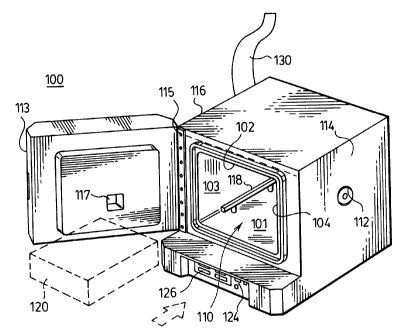
Fi,g. 1 is a perspective view illustrating a
preferred embodiment of an apparatus for analyzing
composite materials according to the present invention;
Figure 2 is a view of the IR radiation source
embedded in the top wall of the oven chamber of t.ie
apparatus; and
Fig. 3 is a cross-sectional front view of the
apparatus of Fig. 1.
DETAILED DESCRIPTION OF THE INVENTION
The present invention now will be described more
fully hereinafter with reference to the accompanying
drawings, in which a specific embodiment of the
invention is shown. This invention may, however, be
embodied in many different forms and should not be
construed as being limited to the embodiments set forth
herein. This illustrated embodiment is provided so
that this disclosure will be thorough and complete, and
will fully convey the scope of the invention to those
skilled in the art. In the drawings, the thickness of
layers and regions are exaggerated for clarity, and
like numbers refer to like elements throughout.
Figs. 1-3 illustrate one embodiment of an
apparatus for analyzing and assaying asphalt-
containing composite materials, e.g., asphalt concrete,
roofing materials and the like, according to the
present invention. As shown in Fig. l, the apparatus
included an oven 100 having a floor 101, a top wall
102, opposing side walls 103, and a rear wall 104 which
collectively define a combustion chamber 110. A door
CA 02274453 1999-06-11
_7_
113 is mounted to one of the side walls 103 by a hinge
115 for providing access to the combustion chamber 110.
A window 117 in the door 113 allows viewing into the
combustion chamber 110 when the door is closed. In the
embodiment illustrated in Figures 1 to 3, the oven
walls 1~1, 102, 103, 104, and door 113 are provided
with a lining 300 of a refractory insulation material.
However, the oven chamber may use other forms of
insulation besides a refractory material, and may be
lined by steel or other materials which are reflective
to IR radiation so as to enhance the effect of the IR
radiation by redirecting the radiation to the sample.
It is further contemplated in a simplified embodiment,
that no insulation or minimal insulation is required.
Provided within the chamber 110 adjacent the floor
is a sample support adapted for receiving and
supporting a sample pan 120 containing a sample of the
paving rnix. In the embodiment illustrated, the sample
support comprises a pair of support rails 118.
However, the sample support may take other forms, such
as a flat panel or sheet. The support rails 118 are
positioned above the floor 101 of the chamber 110 atop
a plurality of posts 108 which pass through openings
109 in the floor 101, with the openings 101 preferably
having a larger diameter than the posts 108 to allow
air to enter the chamber around the posts 108. The
lower ends of posts 108 are in turn supported by a
weighing device, preferably a load cell 128 beneath the
floor 101 of the combustion chamber 110. In this
manner, a sample placed within the chamber 110 may be
continuously weighed during the pyrolysis procedure.
An infrared heater 122 is mounted within the
combustion chamber 110 adjacent the top wall 102 for
CA 02274453 1999-06-11
_g_
emitting infrared radiation downwardly toward the
sample contained in sample pan 120. The infrared
heater includes a block 123 of a refractory material of
high heat capacity which is heated by a heating element
S 124 to a high temperature such that the block radiates
energy in the infrared spectrum. Any infrared heater
capable of emitting radiation at a predetermined
wavelength may be suitably employed. The heating
element 124 for the infrared heater may be of the gas
fired type or may comprise resistance electric heating
elements. One suitable commercially available IR
heater is the Casso-Solar type FHT infrared heater
available from Casso-Solar Corp., Pomona, NY.
According to the present invention, the infrared heater
is operated at a temperature such that infrared
radiation is emitted in the wavelength range of from
about 2 to about 7 um. This corresponds to the
infrared absorption bands found in typical asphalt
binder, and is outside of the range where most
aggregate materials have their absorption spectra. For
the specific infrared heater noted above, infrared
energy of the desired wavelength spectra is emitted
when the infrared heater block 123 is heated to a
temperature of about 1000 degrees Celsius.
The temperature of the IR heater block 123 is
monitored by a suitable temperature sensor 128, such as
a thermocouple or thermistor, embedded in the block
123.
The temperature sensor is connected to a
temperature controller 124, which controls operation of
the heating element 123 to maintain a desired set point
temperature. the heater block temperature and the set
point temperature are displayed by a digital readout
display 126 on the front panel of the oven'. An
additional temperature sensor 129 may be optionally
CA 02274453 1999-06-11
_g_
provided within the combustion chamber for monitoring
the chamber temperature.
In the embodiment illustrated, an exhaust outlet
opening 111 is provided in a side wall 103 of the oven
for discharge of combustion gases produced by pyrolysis
of a sample of composite material. Exhaust pipes or
ducts 130 may be directly connected to the exhaust
outlet opening to carry the combustion gases directly
into the atmosphere or into additional pollution
treatment devices, or laboratory hoods or similar
ventilation apparatus to which the outlet may be
connected. Unlike the heavy black combustion gases
which are produced when burning a sample in a
conventional convection oven, the combustion gases
produced from the infrared oven of the present
invention are much cleaner, and if desired, may be
released directly to the atmosphere without requiring
filtration or afterburning. The infrared radiation is
believed to be scattered by airborne smoke particles,
increasing the efficiency of the oxidization of the
smoke particles. However, an afterburner and/or
filters optionally may be provided to further combust
and/or trap airborne byproducts prior to their release
into the atmosphere.
The oven may also be provided with an additional
air inlet, preferably on the side wall 104 opposite the
side wall where the outlet opening is provided. This
air inlet may be provided with an adjustable air flow
regulator 112 which can be adjusted to compensate for
variations in the exhaust configuration characteristics
of the particular installation. Those skilled in the
art will appreciate that other embodiments of an
adjustable airflow regulator may be used with the
present invention. For example, the air intake control
or regulator may be any type, but is preferably a
rotatable or sliding shutter mechanism. A blower
CA 02274453 1999-06-11
-10-
optionally may be included and may include an
electrically-powered fan which may be controlled, for
example, by a variable speed control which varies the
speed of the fan to vary the output of the blower. The
5 adjustable airflow regulator may also include, for
example, a restrictable opening such as a mechanically
or electromechanically actuated damper or similar
device installed at the exhaust outlet housing, in
portions of the exhaust system connected thereto, or at
10 the holes in the floor of the oven chamber, which may
be adjusted to vary the negative pressure produced by
the blower and thus vary the rate at which gases are
exhausted from the oven.
The sample pan or tray 120 may be made from any
15 non-reactive material able to withstand repeated
heating and cooling cycles. The preferred tray must
have sufficient perforations to allow radiation to
reach the sample from multiple directions. However,
the tray material perforations must be small enough to
20 retain composite material, such as aggregates which are
left behind following the liberation of the asphalt
from the sample. A wire mesh, or metal screen made
from steel or stainless steel able to withstand
temperatures in excess of 1200°to 1500°C are
25 particularly preferred. Other non-metal materials such
as ceramics or other refractory materials may be used
to make the trays.
Conventional furnace trays have a perforated
stainless steel lid to reduce the loss of fine
30 aggregates from the tray system during ignition. It
was determined that the preferred trays for use with
the apparatus of the present invention require no lid
in order to provide maximum IR radiation transfer to
the samples. However, the use of quartz or ceramic
35 lids (highly transparent to infrared radiation) are
also contemplated by the present invention.
In one embodiment of the present invention, the IR
CA 02274453 1999-06-11
-11-
heater source is gas powered. Using such a heater
would ,require only a small about of electrical power
for the controls, and optionally a blower fan. It is
therefore contemplated that the gas fired infrared oven
of the present invention could be electrically powered
with a small battery thus making the unit portable and
deliverable to work and testing sites. This would
obviate the testing delay resulting from sending
samples to testing facilities having ovens located
remotely from the site where the asphalt composite is
being made and applied.
The furnace of the present invention requires a
shorter initial warm-up time than a conventional
convection or conduction furnace, since it is only
necessary to raise the infrared radiator block 123 to
operating temperature, and it is not necessary that the
entire combustion chamber be preheated to an elevated
temperature. In fact, the operating temperature of the
combustion chamber is considerably lower than that of a
convection furnace. The IR furnace takes about 15
minutes to warm up whereas a conventional furnace needs
a 1 to 3 hour warm up period . In addition, the use of
the IR heater facilitates a shorter sample burn time.
The IR furnace takes about 30-40 minutes to complete
combustion whereas a conventional furnace needs at
least 1 hour. Since the infrared radiation from the
heater heats only the sample, and not the air in the
combustion chamber, the overall temperature of the
combustion chamber is much lower. The air is heated
only by the combustion itself and by the heat of the
sample.
In addition, it is further contemplated that no
preheating time may be required, and that sample may be
admitted to the IR furnace prior to activating the IR
heater. The ignition and combustion times in this
"cold start" mode will still be much faster than those
obtained using convection-type furnaces.
CA 02274453 1999-06-11
-12-
Having a lower chamber temperature provides
significant advantages. When a cold sample pan is
first introduced into an oven, temperature differences
between the relatively cold sample and its pan and the
surrounding environment set up air currents. Because
of the necessarily high operating temperature of a
conventional convection oven, and resulting large
temperature differences, significant air currents are
created in the vicinity of the sample pan, which
introduce weight measurement errors when attempting to
measure the initial weight of the sample. The
temperature differences are much lower in the furnace
of the present invention, and the resulting air
currents have minimal error introducing effect.
Further, since the aggregates present in the sample are
heated to lower temperatures and for shorter periods of
time, changes to or losses in the aggregate as a result
of charring, spalling or explosion are minimized. The
use of the IR furnace therefore minimizes mineral
losses and thermal degradation (alteration) of the
aggregate. The minimized heating facilitated by the
apparatus and methods of the present invention further
minimiz& the risk of loss of minerals through
calcination and also lowers the rate of carbonate
dissociation; all of which affects weight measurement
accuracy.
Still further, a lower chamber temperature is
desirable to decrease the effect of temperature
"plunge's as the oven door is opened to admit the sample
trays. In convection ovens, opening of the furnace
door realized a temperature drop on the order of 100°C.
or more, which increased the reheating cycle time. The
combustion chamber temperature in the furnaces of the
present invention typically do not exceed about 300°C
during operating when empty, and only sustain a plunge
of about 25°C as the sample is admitted.
Overall, the chamber temperature is not critical
CA 02274453 1999-06-11
-13-
with the present invention since the radiation is
targeted specifically to the asphalt component of the
composite sample. The asphalt is irradiated with IR
radiation and heats up much more quickly, thus
liberating byproduct gases from the asphalt which are
then ignited in the furnace at much lower temperatures.
The flash point of the asphalt gases is about 315°C.
This is the highest temperature required by the
furnace$ of the present invention. Once the gas
ignites, the sample will burn and the reaction
temperature will rise in excess of 500°C. By contrast,
the known convection furnaces need to provide a chamber
temperature in excess of about 700°C to liberate the
gases required to ignite the sample.
In addition, since the overall internal chamber
temperatures of the present invention are lower,
infrared furnaces may not need thick refractory walls.
This will provide a smaller, lighter structure, and
economize manufacturing. This is important in allowing
for the design of a portable structure that can be used
on site.
The following example serves only to further
illustrate aspects of the present invention and should
not be construed as limiting the invention.
EXAMPLE 1
Combustion of Asphalt-Containing Composite Samples
Two stainless steel sample trays (2.125" x 9" x
13") were used to contain and orient the asphalt
concrete. The tray had perforations having a 0.125"
hole size with 0.1875" hole spacing. This perforation
provided transmission to infrared radiation, with the
stainless steel acting as a reflector for infrared
radiation such that a sufficient amount of infrared
radiation penetrated the perforated bottom of the top
tray and heated the sample in the bottom tray. The
perforations also provided adequate a'ir circulation
CA 02274453 1999-06-11
-14-
necessary for asphalt binder ignition and provided for
a more complete asphalt burn. The sample trays were
not covered in order to provide a more complete
transfer of infrared heat from the infrared source to
the sample on the top tray. A polished stainless steel
flat plate was placed on a regular catch pan. Metal
spacers of about 0.25" height were placed on the flat
plate. On the spacers, were placed the two trays. The
flat metal plate functions as act as a reflector for
infrared and confine the radiation in the sample volume
and keeps any fall-out of asphalt coated grains of
aggregate near the bottom of the second pan. When the
asphalt cement in the second pan ignited, the flames
move towards the flat plate and ignite grains on the
plate. The spacers provide good air circulation
through the sample for quicker ignition and a more even
and complete burn.
After powering up the infrared heaters, it took
about 1S minutes to heat the infrared panel to 975°C.
The chamber temperature was 185°C. The tray system was
weighed. using an external balance. A sample of 10008
of hot asphalt on each sample tray (CC Magnum asphalt
concrete with about 6.5% asphalt content, total sample
weight about 20008). The sample was weighed in the
tray system using an external balance. The tray system
was theh placed in the furnace. In less than 2
minutes, the asphalt in the top tray ignited, and the
process continued igniting asphalt layer-by-layer
downward. Within about 6-8 minutes, the asphalt in the
bottom pan ignited. The chamber temperature reached a
maximum of about 230°C within 10 minutes after placing
the sample into the furnace. When the burn was over,
the sample tray system was removed from the furnace and
allowed to cool down in open air. The total weight of
the tray system was measured using the external
balance.
Many modifications and other embodiments of the
CA 02274453 1999-06-11
-15-
invention will come to mind in one skilled in the art
to which this invention pertains having the benefit of
the teachings presented in the foregoing descriptions
and the associated drawings. Therefore, it is to be
understood that the invention is not to be limited to
the specific embodiments disclosed. In the drawings
and specification, there have been disclosed typical
embodiments of the invention and, although specific
terms are employed, they are used in a generic and
descriptive sense only and not for purposes of
limitation, the scope of the invention being set forth
in the following claims.