Language selection

Search

Patent 2274465 Summary

Third-party information liability

Some of the information on this Web page has been provided by external sources. The Government of Canada is not responsible for the accuracy, reliability or currency of the information supplied by external sources. Users wishing to rely upon this information should consult directly with the source of the information. Content provided by external sources is not subject to official languages, privacy and accessibility requirements.

Claims and Abstract availability

Any discrepancies in the text and image of the Claims and Abstract are due to differing posting times. Text of the Claims and Abstract are posted:

  • At the time the application is open to public inspection;
  • At the time of issue of the patent (grant).
(12) Patent: (11) CA 2274465
(54) English Title: STEEL RULE CUTTING DIE APPARATUS
(54) French Title: APPAREIL A EMPORTE-PIECE A BANDE D'ACIER
Status: Deemed expired
Bibliographic Data
(51) International Patent Classification (IPC):
  • B31B 50/74 (2017.01)
  • B31B 50/14 (2017.01)
  • B26D 7/18 (2006.01)
(72) Inventors :
  • WEBSTER, JAMES (Canada)
  • LAMING, JEFFREY ALLEN (Canada)
  • ARCHER, DAVID JOHN (Canada)
(73) Owners :
  • SHOREWOOD PACKAGING CORPORATION LIMITED (Canada)
(71) Applicants :
  • SHOREWOOD PACKAGING CORPORATION LIMITED (Canada)
(74) Agent: R. WILLIAM WRAY & ASSOCIATES
(74) Associate agent:
(45) Issued: 2006-11-14
(22) Filed Date: 1999-06-11
(41) Open to Public Inspection: 2000-12-11
Examination requested: 2001-03-29
Availability of licence: N/A
(25) Language of filing: English

Patent Cooperation Treaty (PCT): No

(30) Application Priority Data: None

Abstracts

English Abstract


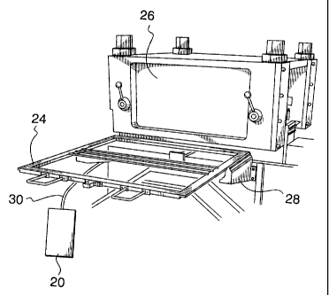
A steel rule cutting die apparatus is described for
manufacturing a carton from a carton blank with
self-cleaning punches for cutting small diameter holes in
a carton blank and waste removal means being a channel
member below the carton blank with an air flow with a
partial vacuum in the channel member so that waste
produced by the punches is removed.


Claims

Note: Claims are shown in the official language in which they were submitted.


The embodiments of the invention in which an exclusive property or privilege
is
claimed are defined as follows:

1. Steel rule cutting die apparatus for manufacturing a carton from a carton
blank
comprising,
(a) a steel rule and cutting die,
(b) one or more self-cleaning punches for cutting one or more holes in a
carton blank,
(c) waste removal means for removing waste pieces after said cutting with a
substantially horizontal elongate channel member below said carton blank,
in use, said channel member having a lid with holes therethrough for said
punches, and
(d) means for providing at least a partial vacuum in said channel member to
draw said waste pieces away from said punches to a waste collection area.

2. Steel rule cutting die apparatus according to claim 1 wherein said holes
correspond in
number and location with said punches, and an air inlet channel at
substantially one
end of said channel member and an outlet channel at substantially an opposite
end of
said channel member.

3. Steel rule cutting die apparatus according to claim 1 or 2 wherein said
means for
providing at least a partial vacuum is a vacuum cleaner machine with said
waste
collection area therein.

4. Steel rule cutting die apparatus according to claim 1, 2 or 3 wherein a
plurality of
channel members is provided.

5. A method of removing waste from steel rule cutting die apparatus for
manufacturing
a carton from a carton blank and having one or more self-cleaning punches for
cutting
one or more holes in the carton blank, providing a substantially horizontal
elongate
channel member beneath said carton blank to receive waste pieces punched out
by


said punches, providing said channel member with a lid having holes
therethrough for
said punches, causing air to flow through said channel member and create a
partial
vacuum whereby said waste pieces pass through said channel member, and
collecting
said waste pieces in a waste collection area.

Description

Note: Descriptions are shown in the official language in which they were submitted.


CA 02274465 1999-06-11
Steel Rule Cutting Die Apparatus
This invention relates to steel-rule cutting and
creasing die apparatus used in the production of
paperboard folding cartons from carton blanks.
Modern production of paperboard folding cartons
features in-line printing, die-cutting and waste
stripping, allowing finished cartons to be processed from
roll stock to finished cartons in one operation.
The stripping of integral waste is normally
conducted post die-cutting and the minimum size of waste
pieces is dictated by engineering of the equipment in use.
It is sometimes desired to cut small holes of 0.5 mm
to 5.0 mm diameter in a paperboard blank. However, it was
previously considered impossible to effectively cut and
cleanly strip the blank.
Self-cleaning punches for this purpose are available
but the difficulty has always been to remove waste which
would, under normal circumstances in an in-line operation,
litter the working area rendering it difficult to produce
quality cartons efficiently.
It is an object of the present invention to provide
apparatus with which it is possible to cut such small
diameter holes in a carton blank wherein the
above-mentioned difficulty is substantially obviated.
Accordingly, there is provided a steel rule and
cutting die, one or more self-cleaning punches for cutting
one or more holes in a carton blank, waste removal means
for removing waste pieces after said cutting with a
channel member below said carton blank, in use, and means
for providing at least a partial vacuum in said channel
member to draw said waste pieces away from said punches to
a waste collection area.
An embodiment of the invention will now be
described, by way of example, with reference to the
accompanying drawings in which:
Figure 1 is a cross-sectional side view of the
embodiment used in a steel rule cutting die for carton
production;

CA 02274465 1999-06-11
- 2 -
Figure 2 is a plan view of the arrangement in Figure
1 with the lid removed;
Figure 3 is a plan view of the pre-drilled lid;
Figure 4 is a diagrammatic representation of part of
a Bobst-Champlain reciprocating die machine showing how
the embodiment could be included,
Figure 5 is a diagrammatic representation in plan
view of a 6-up die incorporating an embodiment of the
invention, and
Figure 6 is a cross-section of part of the die of
Figure 5 on the line VI - VI.
The same reference numerals are used throughout for
like parts.
Referring to the Figures a standard steel creasing
rule 2 (0.923+) is shown with cutting rules 3 (Figures 5
and 6). Nine standard self-cleaning punches 4 (0.937"
high) are provided as shown in Figures 1 and 2 to punch
holes in a carton blank. These can be, for example, 0.5
to 5.0 mm diameter holes. They each have waste ejection
orifices 6 and their orientation can be seen in Figure 2.
Ejected waste scraps, such as 8, are shown in Figures 1
and 2.
A channel member 10 is provided to receive the
scraps 8 and a receiving air pocket is provided by placing
a pocket lid 12 over, and thus closing, the top of the
channel member 10, the lower limit thereof being the flat
surface of the existing die board 11 which extends across
the entire die.
A support frame 14 (Figures 1 and 2) is provided to
support the channel member 10 and the pocket lid 12.
Air is passed through the channel member 10 through
an air inlet portion 16, passes through the channel member
collecting the scraps 8 and passes through an outlet
portion 18 where at least a partial vacuum exists.
To create this partial vacuum and ensure that most,
or all, of the scraps 8 are collected, a vacuum cleaner

CA 02274465 1999-06-11
- 3 -
unit 20, such as a "SHOP-VAC*", is connected to the
channel at outlet 18 and encloses a waste collection
area. An air pocket is thus formed in the channel member
to enhance the flow of scraps 8.
As mentioned above, the channel member 10 has a lid
12 (Figure 3) and this is adhered to the support frame
shoulder 14 by means of double-sided adhesive tape (such
as 15). The lid 12 is made of thin rigid material and is
pre-drilled with holes 22 to fit over the heads of the
punches 4 but, in use, they are above the waste ejection
orifices 6.
The channel member inlet 16 is an air make-up 1/4"
channel routed into 1/16" die board 17 (Figure 2) and
exiting the pocket via a bridge. Similarly, outlet 18 is
a 1/4" channel routed into the die board 17 and connected
to channel member 10 via a natural "bridge" creasing rule
2. A carton blank is, in use, positioned above lid 12.
In Figure 4 part of a Bobst-Champlain reciprocating
die machine is diagrammatically illustrated with the upper
chase or frame 24 pulled out from the upper bolster
portion 26 on external support brackets 28.
The channel member 10 (Figure 1) is below the lower
chase assembly and the outlet 18 emerges through a hole
drilled in the chase by way of a 1/4" tube 30 to the
vacuum cleaner unit 20.
Figures 5 and 6 show a traditional steel rule
cutting and creasing die. This would generally be
produced from maple plywood with slots cut by laser to
accommodate the steel cutting and creasing rules.
A plurality of channel members 10 are shown in
Figure 5 interconnected by a covered channel member 13
similar to the covered channel outlet portion 18. The
channel member inlet 16 is also shown in Figure 5 vented
*Trademark

CA 02274465 1999-06-11
- 4 -
to the outside air and is a channel routed into the die
board.
The entire die would, in use, be fitted into the
steel frame 24 (Figure 4) with the die face downwards.
The die and the frame would be inserted into the cutter
and the cutting action effected by reciprocation of the
upper section of the cutter against the stationary bed
with the stock being fed between the two sections as the
machine reciprocates.
It will be understood that more than one tube 30, of
appropriate size, will normally be provided dependent on
the number of channel members 10.
In one constructed embodiment the apparatus allowed
four cartons to be run in-line with a pattern of two sets
of 9 x 1 mm holes clearly cut and stripped from 8
positions in a die forme.
Although the present invention has been described
and illustrated in detail, it is clearly understood that
the same is by way of illustration and example only and is
not to be taken by way of a limitation, the spirit and
scope of the present invention being limited only by the
terms of the appended claims.

Representative Drawing
A single figure which represents the drawing illustrating the invention.
Administrative Status

For a clearer understanding of the status of the application/patent presented on this page, the site Disclaimer , as well as the definitions for Patent , Administrative Status , Maintenance Fee  and Payment History  should be consulted.

Administrative Status

Title Date
Forecasted Issue Date 2006-11-14
(22) Filed 1999-06-11
(41) Open to Public Inspection 2000-12-11
Examination Requested 2001-03-29
(45) Issued 2006-11-14
Deemed Expired 2009-06-11

Abandonment History

There is no abandonment history.

Payment History

Fee Type Anniversary Year Due Date Amount Paid Paid Date
Registration of a document - section 124 $100.00 1999-06-11
Application Fee $300.00 1999-06-11
Request for Examination $400.00 2001-03-29
Maintenance Fee - Application - New Act 2 2001-06-11 $100.00 2001-06-11
Maintenance Fee - Application - New Act 3 2002-06-11 $100.00 2002-06-10
Maintenance Fee - Application - New Act 4 2003-06-11 $100.00 2003-06-10
Maintenance Fee - Application - New Act 5 2004-06-11 $200.00 2004-06-01
Maintenance Fee - Application - New Act 6 2005-06-13 $200.00 2005-06-13
Maintenance Fee - Application - New Act 7 2006-06-12 $200.00 2006-06-12
Final Fee $300.00 2006-08-17
Maintenance Fee - Patent - New Act 8 2007-06-11 $200.00 2007-06-11
Owners on Record

Note: Records showing the ownership history in alphabetical order.

Current Owners on Record
SHOREWOOD PACKAGING CORPORATION LIMITED
Past Owners on Record
ARCHER, DAVID JOHN
LAMING, JEFFREY ALLEN
WEBSTER, JAMES
Past Owners that do not appear in the "Owners on Record" listing will appear in other documentation within the application.
Documents

To view selected files, please enter reCAPTCHA code :


To view images, click a link in the Document Description column. To download the documents, select one or more checkboxes in the first column and then click the "Download Selected in PDF format (Zip Archive)" or the "Download Selected as Single PDF" button.

List of published and non-published patent-specific documents on the CPD .

If you have any difficulty accessing content, you can call the Client Service Centre at 1-866-997-1936 or send them an e-mail at CIPO Client Service Centre.


Document
Description 
Date
(yyyy-mm-dd) 
Number of pages   Size of Image (KB) 
Cover Page 2000-12-04 1 37
Representative Drawing 2000-12-04 1 17
Claims 1999-06-11 2 55
Description 1999-06-11 4 168
Abstract 1999-06-11 1 12
Drawings 1999-06-11 4 102
Claims 2004-02-05 2 50
Drawings 2004-02-05 4 88
Claims 2005-05-02 2 49
Representative Drawing 2006-10-17 1 16
Cover Page 2006-10-17 1 40
Assignment 1999-06-11 8 167
Prosecution-Amendment 2001-03-29 1 37
Fees 2003-06-10 1 31
Prosecution-Amendment 2003-08-05 1 30
Prosecution-Amendment 2004-09-23 2 45
Fees 2001-06-11 1 41
Fees 2002-06-10 1 37
Prosecution-Amendment 2004-02-05 8 172
Prosecution-Amendment 2004-03-23 2 61
Fees 2004-06-01 1 35
Prosecution-Amendment 2005-05-02 6 158
Prosecution-Amendment 2004-11-02 2 88
Fees 2005-06-13 1 32
Fees 2006-06-12 1 38
Correspondence 2006-08-17 1 37
Fees 2007-06-11 1 38