Note: Descriptions are shown in the official language in which they were submitted.
CA 02274505 1999-06-07
WO 98/27406 PCT/GB97/03454
_I_
Distributed Strain and Temperature Sensing System
The present invention relates to an apparatus for the simultaneous measurement
of
temperature and strain in optical waveguides and, in particular, relates to
strain and
temperature measurements in monomode optical fibres.
There is a need to monitor distributions of temperature and/or strain in many
fields of
engineering from power station steam pipes to smart structures and aircraft
bodies. The
sensors often need to cover large volumes, to be integrable into complex
structures and to
be immune from interference by electromagnetic fields. Optical-fibre sensors
should be
able to fulfil these requirements. Commercial sensing systems are available
which use
optical fibres to measure temperature distributions. However, these systems
are not
capable of measuring distributed strain. If strain could be measured then the
fibres could
be embedded into critical structures, such as aircraft components, bridges and
dams and be
used to give advance warning of possible failure. The measurement of strain
would also
allow the measurement of pressure, since the act of squeezing a fibre extends
it. A
particular application for such a system is in the field of oil exploration
where the fibre can
be used as a distributed pressure (and temperature) sensor down a bore hole.
Optical-fibre sensors which measure variations of a parameter along the fibre
length can be
divided into two classes: quasi-distributed and fully distributed. In quasi-
distributed
sensing, certain sections of the fibre are modified and used for local
measurement and the
rest is used simply to carry the light from sensor to sensor and, finally, to
the detector. In
fully distributed sensing, the fibre is unmodified and the whole length is
used for light
transmission and sensing. Fully distributed sensors are the more flexible and
can be used
with fibres already in place, allowing applications such as diagnostics of
optical-fibre
communication networks.
A possible technique for the fully distributed measurement of
strain/temperature is based
on the Brillouin effect. Here, a fraction of the optical power launched down a
fibre is
scattered at some point in the fibre, causing it to change optical wavelength
and return
towards the optical source. Critically, the wavelength of the returning light
depends upon
the strain/temperature of the fibre at the point at which the light was
scattered. The
wavelength of the returning light can then be measured to yield the
strain/temperature in
the fibre from the point at which the returning light was generated. If the
incident light is
SUBSTITUTE SHEET (RULE 26)
CA 02274505 1999-06-07
WO 98/27406 PCT/GB97/03454
2
launched as a short pulse, then by recording the wavelength of the returning
light as a
function of time, the strain/temperature at all points along the fibre can be
measured.
There are two techniques which can be used to detect strain only, or
temperature only,
from the measurement of the Brillouin shift: ( 1 ) using a pump-probe system
to produce
frequency-dependent Brillouin power; (2) using optical heterodyning to detect
the
Brillouin signal. However, both methods require special arrangements of fibres
to
deconvolve the temperature and strain information. For example, one solution
that has
been suggested is to pass a single fibre twice over the same region in such a
way that one
section is isolated from the strain and only affected by temperature. This
approach makes
the installation of the sensing optical fibre cable complicated and cannot be
used with the
existing optical fibre networks.
If it is desired to measure strain and temperature simultaneously along the
same length of a
single optical fibre, then both the amplitude and frequency shift of the
Brillouin
backscattered light has to be detected. Technique ( 1 ) would fail, as the
stimulated
Brillouin power produced would be practically independent of the temperature
and strain
due to the non-linear interaction of the pump and probe beams. Technique (2)
would have
difficulties due to polarisation noise-induced signal fading.
Another technique (3), used in the detection of temperature, is to measure the
power of the
Brillouin backscattered signal using a narrow bandwidth optical filter.
However, this is
not practical as: 1 ) amplitude variations due to drift in the optical filter
response and the
optical source wavelength; 2) strain cannot be determined from measuring only
the
Brillouin backscatter power.
We have devised a distributed sensing system which overcomes these
difficulties.
The technique we have devised provides for referencing to overcome any optical
filter or
source frequency drift and to accurately detect both the amplitude and
frequency of the
Brillouin scattered light as a function of time and, therefore, allowing
simultaneous
measurement of strain and temperature distributions along the same length of
optical fibre.
_~ _. . .. .~_...~.~_.T__.... .~_....._..
CA 02274505 1999-06-07
WO 98/27406 PCT/GB97/03454
3
According to the present invention there is provided apparatus for
simultaneous
measurement of temperature and strain distributions, which apparatus comprises
a light
source for generating pulses of light, a sensing network which comprises at
least one
optical fibre down which can pass pulses of light generated by the light
source, a
conversion means adapted to convert physical parameters into changes of strain
or
temperature along the sensing optical fibre thereby modifying the spectral
response of the
backscattered light passing back down the optical fibre (Brillouin backscatter
and
Rayleigh backscatter si.gnals), a reference section subjected to known
magnitude of the
physical parameters, a receiver means in which a portion of returned light is
passed on to a
scanning optical filter able to resolve the Rayleigh peaks and Brillouin peaks
and in which
the optical signals are converted to electrical signals which are then fed
into a processor
means; the scan rate of the scanning optical filter being slower than the
repetition of the
optical pulses allowing the spectral light of the backscattered light to be
recorded along the
length of the optical fibre and both the amplitude and frequency shift of the
Brillouin
peaks relative to the Rayleigh peaks to be accurately measured from which
temperature
and strain distributions along the same length of optical fibre can be
determined.
Light is transmitted down the optical fibre and backscattered light is
transmitted back
down the fibre. This light will be predominately of the same wavelength as the
transmitted
light (the Rayleigh peak), but some of the light will have a frequency shift
due to the
interaction of the energy of the vibrational state of the optical fibre and
the light (the
Brillouin peaks). There can be either addition of energy to the light, which
gives
backscattered light of a shorter wavelength (anti-Stokes scattering) or there
can be removal
of energy from the light which gives backscattered light of longer wavelength
(Stokes
scattering). The amplitude of the Brillouin peaks and the frequency shift of
the Brillouin
peaks compared with the Rayleigh peak is a measure of the strain and the
temperature of
the optical fibre at the position from where the light is backscattered.
The light source preferably generates coherent light in the visible or
infrared spectrum, e.g.
it is a laser, and conventional lasers can be used. The light source can be a
narrow
linewidth laser and it can be a solid-state laser, semiconductor laser diode
or fibre laser
source and it can include an external cavity for controlling the linewidth and
the operating
wavelength.
CA 02274505 1999-06-07
WO 98/27406 PCT/GB97/03454
4
The modulating means pulses the light from the light source so that light is
transmitted
down the optical fibres in pulses, the light can be modulated using Q-
switched, mode-
locked or direct modulation techniques or it may be modulated by an external
modulator
such as an acoustic optic modulator or an integrated optics modulator.
Preferably there is an amplifying means which can amplify the backscatter
light and
optical pulses. Optical amplifiers may be used to amplify the optical signals
at the
transmitter, receiver and in the sensing network means and the amplifiers may
be solid
state semiconductor or optical fibre amplifiers.
The conversion means converts the parameter to be measured to a strain or
temperature
change in the optical fibre, for example if movement within the structure is
to be
measured the conversion means can be means which attaches the fibre to the
structure. For
measuring pressure or detecting electric fields within the structure piezo
electric devices
can be incorporated. If microwave radiation is to be detected the fibre can be
coated with a
conductor such as graphite.
In order to improve the quality of the signals and to separate the Brillouin
peaks from
background noise, it is preferable to superimpose and average a series of
signals so that an
improved signal to noise is obtained. However, owing to variables such as
drifts in optical
filter response and source wavelength etc., this has not been conventionally
practical.
However, we have found that if the backscattered signal is normalised with
reference to
the Rayleigh peaks which are larger (about sixty times) than the Brillouin
peaks and are
relatively insensitive to temperature and strain and then the normalised
signals averaged
and superimposed, the Brillouin peaks are obtained with a much better signal
to noise
ratio.
The rate of scan of the optical filter is at a much slower rate than the pulse
repetition rate
of the pulses of light. This enables the wavelength spectra of the
backscattered light to be
recorded for each section along the optical fibre. The position from where the
backscattered light comes is determined by the time interval between the
transmission of
the pulse and the return of the backscattered light.
In operation a pulse of light is transmitted down the optical fibre and the
filter is set to a
narrow bandwidth, when the return of backscattered light within this filter
range is
CA 02274505 1999-06-07
WO 98/27406 PCT/GB97I03454
received at a noted time (which gives the location down the optical fibre of
the position
where the backscattered light comes from), the amplitude and the optical pass
frequency
are noted, by doing this for several time intervals and several optical pass
frequencies,
spectra at various locations along the optical fibre can be obtained. The
filter is set so that
the Rayleigh peak (which is at the frequency of the transmitted light) is
detected and the
bandwidth of the filter will also detect the Brillouin peaks. In operation the
optical filter
scans the wavelength across a range to detect the Brillouin peaks and the
Rayleigh peaks.
This process can be carried out for many locations down the optical fibre for
each pulse of
light.
The operating wavelength of the optical source means and/or the dispersion
characteristics
of the sensing optical fibres may be adjusted in such a way that the pulse and
generated
forward scatter Raman Stokes signals travel down the optical fibre with
different
propagation velocities and they walk-off over a sufficient length to avoid
stimulated
Raman scattering and thereby allowing high pump powers and longer sensing
optical
fibres to be used.
There is section of the optical fibre at a known temperature and strain which
can be used
as a reference and by measuring the amplitude and frequency shift of the
Brillouin peaks
for the reference section to calibrate the data received from other points
into temperature
and strain measurements.
Preferably a filter such as an interference filter, e.g. as a Fabry-Perot
interferometer, is
used to resolve the Brillouin spectrum. Conventionally, such interferometers
are chosen
such that the entire spectrum of interest lies within one free spectral range
(FSR) of the
interferometer. The FSR is the frequency range within which all spectral
information will
be displayed such that any peaks with frequency outside the FSR will still be
displayed
inside the FSR. However, this is conventionally undesirable as it may lead to
an
unpredictable overlapping of peaks. Preferably in the present invention, the
FSR is chosen
to be less than the Brillouin shift. This enables some of the frequency band
between the
Brillouin peaks and the Rayleigh peak not to be scanned and so a much smaller
scan
range can be used to capture the spectral response.
For the same spectral resolution, this technique requires the collection of
around one
hundredth of the points required by the conventional technique. Since the data
are usually
CA 02274505 1999-06-07
WO 98/27406 PCT/GB97/03454
6
handled many times in data processing programs, this yields a great saving on
the time
required to make the strain and temperature measurements.
In order to measure the temperature, the ratio of the amplitude of the
Brillouin peaks
against the Rayleigh peaks is measured and the frequency shift is a measure of
the strain.
The optical signals obtained are converted into electrical signals, fed into a
computer and
recorded in the desired form. The reference signal is generated by the
reference section
and this is preferably fed into the same computer.
The detection means may be low-noise photodetectors with internal gain such as
avalanche photodiodes.
In order to form a larger sensing network, a plurality of optical fibres or
optical fibre
cables can be dispersed in the structure to be monitored, e.g. a pipe circuit
or downhole in
a rock formation. By use of the apparatus and method of the invention, the
temperature
and strain can be measured at any point.
The measurements are calibrated with respect to the spectral response of the
sensing
section and the strain and temperature distribution along the sensing fibre
are computed by
measuring the relative amplitude and position of BriIlouin peaks.
The invention is described with reference to the accompanying drawings in
which:-
Figure I is a diagram of an embodiment of the present invention, in which
optical fibres are
used and the source means is externally modulated and then amplified.
Figures 2-4 are diagrams of traces of backscattered light recorded at
different scanning
positions of the optical filter means showing how the spectral responses at
different
sensing locations are computed and the drift in the optical filter and the
source wavelength
are corrected for, prior to signal averaging.
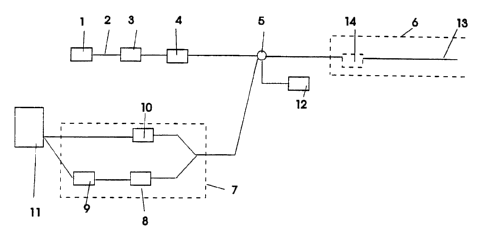
Referring to Fig. 1, a light source (1) comprising a laser is connected by
optical fibre (2) to
a pulse modulator (3} which transmits light in pulses and then to light
amplifier (4). The
optical fibre passes through coupler (S).
~__ T ___._._._
CA 02274505 1999-06-07
WO 98/27406 PCT/GB97/03454
7
In the structure to be monitored, shown generally at (6), the optical fibre
(13) is fed
through the structure where the strain and temperature is to be measured.
There is a
reference section at (14) where the temperature and strain is known to be used
as a
calibration measurement.
A detection means (12) may be used to monitor the light transmitted to the
sensing
network means (6). At the receiver unit (7), a portion of the backscattered
light is passed
onto a scanning optical filter (8) which selects a narrow range of
wavelengths. The optical
power of the selected wavelength range is measured and converted to electrical
signals
using the detection unit (9). Another portion of light is also directly
monitored with a
detection unit ( 10) for measuring the Rayleigh backscattered light for each
measurement
point. A computing means ( 1 I ) records the returned backscattered light as a
function of
time. The optical filter (8) is scanned at a slower rate compared to the pulse
repetition rate
of the source means ( 1 ). This allows the backscattered light to be captured
at different
selected wavelengths by sending many optical pulses during one scan cycle. The
backscattered traces are combined to construct the full spectral response of
the
backscattered light along the sensing fibre, as indicated in Figure 2. Each
spectral
response, corresponding to a different section of fibre, is normalised with
reference to its
Rayleigh peak which is insensitive to temperature and strain and is relatively
immune to
signal noise. In addition, the output of detection unit ( 10) can be used to
normalise each
measurement point relative to Rayleigh signal and to compare it with the
Rayleigh peaks
detected with detection unit (9) after passing through optical filter (8) to
improve the
measurement accuracy. The measurements are calibrated with respect to the
spectral
response of the sensing section (13) and the strain and temperature
distribution along the
sensing fibre are computed by measuring the relative amplitude and position of
Brillouin
peaks.
Referring to Figs. 2, 3 and 4:-
Figure 2
The figure shows the results from positions I to 5 on the optical fibre (13).
As an optical
pulse propagates down the waveguide, the pass frequency of the optical filter
is noted and
the returning signal is measured as a function of time. After a short time, to
allow the pass
frequency of the filter, which is scanning slowly, to increase, a second pulse
is launched,
the pass frequency is again noted and the returning signal is again measured
as a function
CA 02274505 1999-06-07
WO 98/27406 - PCT/GB97/03454
8
of time. Referring to position 1 the filter is set to the frequency fi and the
amplitude of the
backscattered light at that frequency is measured, this is repeated for
frequencies f2, 3 etc.
to obtain the spectrum at position 1 shown as fi ~, flz and f13 etc.
Corresponding
measurements are simultaneously made for each pulse at positions 2 to 5 along
the optical
fibre (13), the result for position 2 is shown as f2~, 22; the result for
position 3 is shown as
f3j, f32; the result for position 4 is shown as 4i, aae the result for
position S is shown as
s ~ ° sz respectively.
The process is continued until the entire frequency spectrum is collected. A
computer
program then transposes the data such that it is stored in arrays containing
the frequency
spectra at the positions of interest in the fibre (the frequency spectra shown
at positions 1-
S in the fig.). A peak detection program then measures the height of the peaks
and their
mutual frequency separation and from this the temperature and strain at the
positions of
interest (here positions 1-5) are deduced. The process used to average the
data, if required,
is specified in Figure 3.
Figure 3
This figure illustrates the averaging technique for obtaining better spectra.
For each filter
scan the spectrum at each location may be slightly displaced so that if they
are averaged
the type of spectrum shown in spectrum 3 is obtained.
Spectra 1 and 2 represent frequency spectra recorded from the same position in
the fibre,
at different times, with the purpose of averaging the spectra to reduce noise.
Due to the
drifts of optical filters, laser sources and variations in the scan position
etc. the spectra
appear to have shifted relative to one another. If conventional averaging were
used, this
would cause significant broadening of the processed spectrum and so give
inaccurate
temperature and strain measurement as shown in spectra 3.
A technique is used whereby peak detection scheme finds the dominant Rayleigh
peak and
"shifts" the spectra to be averaged such that the Rayleigh peaks of each
spectra are
overlaid this gives the improved result shown in spectra 4. This technique is
reliable as (1)
the Rayleigh peak is insensitive to temperature and strain; (2) the Rayleigh
peak is large
(about sixty times larger than the Brillouin peaks) and so relatively immune
from noise;
(3) any filter drift affects the peaks equally.
CA 02274505 1999-06-07
WO 98/27406 PCT/GB97/03454
9
Figure 4
The conventional use of an optical filter in analysing the Brillouin spectrum
is shown in
Fig. 4a. Here the FSR is greater than the frequency difference between the
Brillouin
peaks, and many data points have to be collected to capture the spectral
response. In this
embodiment, the FSR is chosen to be less than the Brillouin shift. Here the
Brillouin
peaks are "projected back" and a much smaller scan range is used to capture
the whole
spectrum.
For the same spectral resolution, this technique requires the collection of
around one
hundredth of the points required by the conventional technique. Since the data
are usually
handled many times in data processing programs, this yields a great saving on
the time
required to make the strain and temperature measurements.