Language selection

Search

Patent 2274704 Summary

Third-party information liability

Some of the information on this Web page has been provided by external sources. The Government of Canada is not responsible for the accuracy, reliability or currency of the information supplied by external sources. Users wishing to rely upon this information should consult directly with the source of the information. Content provided by external sources is not subject to official languages, privacy and accessibility requirements.

Claims and Abstract availability

Any discrepancies in the text and image of the Claims and Abstract are due to differing posting times. Text of the Claims and Abstract are posted:

  • At the time the application is open to public inspection;
  • At the time of issue of the patent (grant).
(12) Patent Application: (11) CA 2274704
(54) English Title: LOW PRESSURE, FULL COVERAGE FLUIDIC SPRAY DEVICE
(54) French Title: DISPOSITIF DE PULVERISATION DE FLUIDES BASSE PRESSION POUR COUVERTURE INTEGRALE
Status: Dead
Bibliographic Data
(51) International Patent Classification (IPC):
  • B05B 1/08 (2006.01)
  • F15C 1/22 (2006.01)
(72) Inventors :
  • RAGHU, SURYA (United States of America)
  • STOUFFER, RONALD D. (United States of America)
(73) Owners :
  • BOWLES FLUIDICS CORPORATION (United States of America)
(71) Applicants :
  • BOWLES FLUIDICS CORPORATION (United States of America)
(74) Agent: NA
(74) Associate agent: NA
(45) Issued:
(86) PCT Filing Date: 1997-09-09
(87) Open to Public Inspection: 1998-03-19
Availability of licence: N/A
(25) Language of filing: English

Patent Cooperation Treaty (PCT): Yes
(86) PCT Filing Number: PCT/US1997/015314
(87) International Publication Number: WO1998/010870
(85) National Entry: 1999-06-11

(30) Application Priority Data:
Application No. Country/Territory Date
08/713,276 United States of America 1996-09-12
08/768,935 United States of America 1996-12-18

Abstracts

English Abstract


A two-stage liquid spray device having an outlet region with an island (41)
and an exit aperture (47) and a fluidic oscillator (33) driving said outlet
region. The improvement for the spray device is operable at a low pressure to
achieve full-area coverage with substantially uniform droplets and wherein all
of the spray droplets land on the desired work surface and do not bounce. The
fluidic oscillator includes an oscillation chamber (33), a power nozzle (31)
for introducing a jet of liquid from a source into the oscillation chamber.
The oscillation chamber is configured to produce a pair of alternating control
vortices which substantially preclude wall attachment of said jet traversing
said oscillation chamber, thus avoiding a heavy endedness in the oscillatory
jet. An outlet from the oscillation chamber to the outlet region, whereby the
jet rhythmically sweeps in end pulses to each side of the island and forms a
sheet at the exit aperture. The sheet is rhythmically waved or swept in the
ambient air to form the uniform droplets. A transverse slot defines the
lateral boundary of the sweeping sheet.


French Abstract

Dispositif de pulvérisation de liquide à deux étages, comportant une zone de distribution présentant un îlot (41), un orifice de sortie (47) et un oscillateur (33) fluidique actionnant cette zone de distribution. L'amélioration du dispositif de pulvérisation se caractérise par un fonctionnement à basse pression permettant de réaliser une couverture complète d'une zone au moyen de gouttelettes sensiblement uniformes, toutes ces goutelettes arrivant sur la surface de travail choisie sans rebondir. L'oscillateur fluidique comporte une chambre d'oscillation (33), une buse de propulsion (31) pour introduire un jet de liquide depuis une source dans la chambre d'oscillation. La chambre d'oscillation est formée de manière à générer deux tourbillons de commande alternés qui permettent d'éviter dans une large mesure que le jet ne se dépose sur les parois lorsqu'il traverse la chambre d'oscillation et ne provoque un épaississement de la fin du jet oscillatoire. Un orifice de sortie conduit de la chambre d'oscillation à la zone de distribution, le jet balaye rythmiquement par pulsations complètes de chaque côté de l'îlot et forme une nappe à l'orifice de sortie. Cette nappe est ondulée ou balayée rythmiquement dans l'air ambiant pour former des gouttelettes uniformes. Une fente transversale définit la limite latérale du mouvement de balayage de la nappe.

Claims

Note: Claims are shown in the official language in which they were submitted.


WHAT IS CLAIMED IS:
1. In a two-stage liquid spray device having an
outlet region with an island therein and an exit aperture
and a fluidic oscillator connected to and driving said
outlet region, the improvement comprising:
said fluidic oscillator includes an oscillation
chamber,
a power nozzle for introducing a jet of liquid from a
liquid source into said oscillation chamber,
said oscillation chamber mirror image sidewalls being
shaped to produce a pair of alternating control vortices
which substantially preclude wall attachment effects of
said jet traversing said oscillation chamber, and an outlet
from said oscillation chamber to said outlet region,
whereby said jet rhythmically sweeps in said outlet and
rhythmical pulses on each side of said island to said exit
aperture,
and a sheet of liquid is swept to form said uniform
droplets whereby said spray device achieves full-area
coverage with substantially uniform liquid droplets and
wherein all of the spray droplets land on a selected work
surface.
2. The spray device defined in Claim 1 including a
slot extending transverse to said exit aperture for
defining the boundary of said sweeping sheet.
3. In a two-stage liquid spray device for spraying
a selected work surface, and two-stage spray device having
an outlet region with an island therein and an exit
aperture for delivering said liquid to said selected work
surface and a fluidic oscillator connected to and driving
said outlet region, wherein the improvement comprising:
said fluidic oscillator includes an oscillation
chamber,


7
a power nozzle for introducing a jet of liquid from a
liquid source into said oscillation chamber,
said oscillation chamber having substantially mirror
image sidewalls shaped to produce a pair of alternating
control vortices which substantially preclude wall
attachment effects of said jet traversing said oscillation
chamber,
an outlet from said oscillation chamber to said outlet
region, whereby said jet rhythmically sweeps in said outlet
and rhythmical pulses on each side of said island to said
exit aperture,
and a sheet of liquid issues through said exit
aperture and is swept to form said uniform drops.
4. The spray device defined in Claim 3 including a
slot extending transverse to said exit aperture for
defining the lateral ends of said sweeping sheet.
S. In a two-stage liquid spray device having an
outlet region with an island and an exit aperture and a
fluidic oscillator, driving said outlet region, wherein the
improvement comprises:
said fluidic oscillator including an oscillation
chamber,
a power nozzle for introducing a jet of liquid from a
liquid source into the oscillation chamber,
said oscillation chamber having mirror image sidewalls
shaped to produce a pair of alternating control vortices
which substantially preclude wall attachment of said jet
traversing said oscillation chamber,
an outlet from said oscillation chamber connected to
said outlet region,
whereby the jet rhythmically pulses to each side of
said island to form a sweeping sheet at said exit aperture
to form the uniform droplets, and


8
a transverse slot contiguous to said exit aperture for
defining the lateral boundary of the sweeping liquid sheet.

Description

Note: Descriptions are shown in the official language in which they were submitted.


CA 02274704 1999-06-11
WO 98/10870 PCT/US97/I5314
- LOW PRESSURE, FULL COVERAGE
FLUIDIC SPRAY DEVICE
RELATED APPLICATION
This application is a continuation-in-part application
of copending application Serial No. 08/713,276 filed
September 12, 1996 entitled LOW PRESSURE, FULL COVERAGE
FLUIDIC SPRAY DEVICE.
BACKGROUND OF THE INVENTION
Fig. 1 hereof, from Stouffer Patent No. 4,151,955
(incorporated herein by reference), discloses a two-stage
fluidic spray device in which a wall attachment, heavy-
ended type of fluidic oscillator 10 drives a generally
circular outlet region or chamber 11. Outlet region 11 has
a substantially concentric island 12 which converts the
fluidically swept jet issuing from fluidic oscillator to
sweeping sheet. Fig. 2, from Stouffer Patent No. 4,508,267
(incorporated herein by reference) discloses a liquid
oscillator for producing a unidirectional swept jet for
producing a fan spray 16 with resulting liquid droplets of
uniform size. Alternating control vortices are formed in
the oscillation chamber 17 and preclude the wall attachment
effects which make the fluidic oscillator portion or spray
shown in Fig. 1 heavy-ended.

CA 02274704 1999-06-11
WO 98/10870 PCT/tTS97/15314
2
We have discovered that a two-stage liquid spray
device having an outlet region with an island of the type
illustrated in Stouffer Patent No. 4,151,955 and a fluidic
oscillator of the type shown in Stouffer Patent No.
4,508,267 can be operated at low pressure (as from a pumped
source or a plastic squeeze container) to achieve full-area
coverage with substantially uniform droplets and wherein
all of the spray droplets land on the desired work surface
and do not bounce. In other words, the liquid droplets stay
on the work surface in the desired pattern.
The exit aperture from the outlet stage to ambient is
provided with a transverse groove to define the extent of
the oscillating liquid sheet forming the spray.
The object of the present invention is to provide a
liquid spray device for full area coverage which operates
at low pressure and velocity and which produces
substantially uniform droplets in the full area coverage
spray.
According to a preferred embodiment of the invention,
a two-stage fluidic spray device in which a fluidic
oscillator has an oscillation chamber configured so that
alternate control vortices cause a power jet to oscillate
back and forth in the oscillation chamber without
significant wall attachment effects. The output of the
fluidic oscillator drives an island type output region.
The exit aperture or opening from the outlet region to
ambient is provided with an external transverse groove or
__ .._ _ ___ _ ~__~.._ _. .~_._.___ _

CA 02274704 1999-06-11
WO 98/10870 PCT/US97/15314
3
slot which defines the lateral boundaries of the spray
pattern of liquid and substantially eliminates any drip.
BRIEF DESCRIPTION OF THE DRAWINGS
The above and other objects, advantages and features
of the invention will become more apparent when considered
in conjunction with the following specifications and
accompanying drawings, wherein:
Fig. 1 (prior art) is a silhouette of a two-stage
spray device disclosed in Fig. 20 of Stouffer Patent No.
4,151,955;
Fig. 2 (prior art) is a silhouette of a fluidic
oscillator disclosed in Stouffer Patent No. 4,508,267;
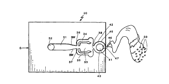
Fig. 3 is a silhouette of a two-stage fluidic spray
device incorporating the invention;
Fig. 4 is a front elevational view of a two-stage
spray device incorporating the invention; and
Fig. 5 is an isometric perspective view of a two-stage
spray device incorporating the invention.
DETAILED DESCRIPTION OF THE INVENTION
Referring now to Fig. 3, a two-stage liquid spray
device 30 incorporating the invention has a power nozzle 31
coupled via passage 32 to a source of liquid to be sprayed
or dispersed in a predetermined pattern onto a desired
surface. The source S may be a pumped source or a plastic
squeeze bottle or other source of liquid. The liquid can

CA 02274704 1999-06-11
WO 98110870 PCT/US97/15314
4
be a wash/wax, water, etc. liquid. Power nozzle 31 has
converging side walls SW and issues a jet of liquid into
oscillation chamber 33. As described is Stouffer Patent
No. 4,508,267, alternating control vortices are formed in
the oscillation chamber 33 with the alternating vortices
controlling the flow of liquid in control passages 34 and
35 and control ports 36 and 37 causing the liquid jet to
rhythmically oscillate back and forth in the oscillation
chamber 33. The jet of liquid is swept or oscillated in
outlet 38 which constitutes the inlet to outlet region 39
which is constituted by a generally circular (in this
embodiment} outlet chamber 40 having outlet island 41. The
rhythmic sweeping of the jet of liquid in outlet 38 causes
the rhythmic pulsing of liquid in the passages 42 and 43 on
the two sides of the island 41 to impinge at tip or point
44 thus producing an oscillating sheet 46 oriented
perpendicular to the impingement direction of the liquid
jets at the exit 47. The oscillating sheet of liquid 46
breaks up into uniform droplets 50 thus providing a uniform
coverage over a predetermined area of the deposit surface.
The end of the nozzle is diamond-shaped as shown in
Figs. 4 and 5, and laterally extending groove or channel 60
is provided to define the boundary of the oscillating sheet
where it leaves exit 47 to obtain the desired shape of the
spray. The groove 60 is also designed to drain off the
accumulating liquid at the edges . The slot or groove 60
geometry produces the required expansion of the oscillating

CA 02274704 1999-06-11
WO 98/10870 PCT/I1S97/15314
'
sheet of liquid issuing to ambient through the outlet
aperture 47.
While I have shown and described preferred embodiments
of the invention, it will be appreciated that other
5 embodiments, modifications and adaptations of the invention
will become readily apparent to those skilled in the art.
Representative Drawing
A single figure which represents the drawing illustrating the invention.
Administrative Status

For a clearer understanding of the status of the application/patent presented on this page, the site Disclaimer , as well as the definitions for Patent , Administrative Status , Maintenance Fee  and Payment History  should be consulted.

Administrative Status

Title Date
Forecasted Issue Date Unavailable
(86) PCT Filing Date 1997-09-09
(87) PCT Publication Date 1998-03-19
(85) National Entry 1999-06-11
Dead Application 2003-09-09

Abandonment History

Abandonment Date Reason Reinstatement Date
2002-09-09 FAILURE TO PAY APPLICATION MAINTENANCE FEE
2002-09-09 FAILURE TO REQUEST EXAMINATION

Payment History

Fee Type Anniversary Year Due Date Amount Paid Paid Date
Registration of a document - section 124 $100.00 1999-06-11
Reinstatement of rights $200.00 1999-06-11
Application Fee $300.00 1999-06-11
Maintenance Fee - Application - New Act 2 1999-09-09 $100.00 1999-07-26
Maintenance Fee - Application - New Act 3 2000-09-11 $100.00 2000-08-08
Maintenance Fee - Application - New Act 4 2001-09-10 $100.00 2001-08-29
Owners on Record

Note: Records showing the ownership history in alphabetical order.

Current Owners on Record
BOWLES FLUIDICS CORPORATION
Past Owners on Record
RAGHU, SURYA
STOUFFER, RONALD D.
Past Owners that do not appear in the "Owners on Record" listing will appear in other documentation within the application.
Documents

To view selected files, please enter reCAPTCHA code :


To view images, click a link in the Document Description column. To download the documents, select one or more checkboxes in the first column and then click the "Download Selected in PDF format (Zip Archive)" or the "Download Selected as Single PDF" button.

List of published and non-published patent-specific documents on the CPD .

If you have any difficulty accessing content, you can call the Client Service Centre at 1-866-997-1936 or send them an e-mail at CIPO Client Service Centre.


Document
Description 
Date
(yyyy-mm-dd) 
Number of pages   Size of Image (KB) 
Cover Page 1999-09-01 1 65
Description 1999-06-11 5 160
Representative Drawing 1999-09-01 1 5
Abstract 1999-06-11 1 55
Claims 1999-06-11 3 100
Drawings 1999-06-11 3 45
Fees 2000-08-08 1 35
Correspondence 1999-07-21 1 2
Assignment 1999-06-11 3 116
PCT 1999-06-11 9 340
Assignment 1999-07-26 4 232
Fees 2001-08-29 1 34
Fees 1999-07-26 1 36
Correspondence 2008-04-10 1 38
Correspondence 2008-05-21 1 14
Correspondence 2008-05-21 1 21