Note: Descriptions are shown in the official language in which they were submitted.
CA 02274765 1999-06-08
WO 99/20323 PCT/US98/21119
Fluid Collection Cassette Identification Scheme
Background of the Invention
1. Field of the Invention
This invention relates to fluid collection cassettes used in surgical systems
and, more particularly, to a scheme for identifying particular fluid
collection cassettes.
2. Related Art
Ophthalmic microsurgical systems typically are classified in accordance with
the surgical area of the eye to which the system is directed. Therefore,
certain
ophthalmic microsurgical systems are considered to be anterior systems, while
others
are considered to be posterior systems. Occasionally, these systems may be
combined
into one system which operates in both the anterior and posterior regions of
the eye.
In all ophthalmic microsurgical systems, some type of fluid collection
reservoir is utilized to collect fluid byproducts of the surgical operation.
The fluid
reservoir may take various forms. One form which is well known in the art is a
fluid
collection cassette which is a hard plastic cassette defining a fluid
collection reservoir.
The prior art associated with such fluid collection cassettes utilize a reflux
2 0 bulb member attached at one end to the inlet of the fluid collection
cassette and at the
other end to a tube which is itself connected to the hand piece.
Regardless of the type of operating procedure used, posterior or anterior, the
size of the cassette remains constant. In fact, the only physical distinction
that can be
made between a cassette for posterior surgery and a cassette for anterior
surgery is the
CA 02274765 1999-06-08
WO 99/20323 PCT/US98/21119
size of the volume contained within the respective reflux bulbs. The volume
contained within the posterior surgery reflux bulb is approximately 1/10 (one
tenth)
the volume of the anterior reflux bulb. This difference in volumes is made
necessary
from the very nature of the surgery itself.
During surgery, the fluid line between the handpiece and the fluid collection
cassette may occasionally become clogged. When this occurs, a preferred way to
unclog the line is to exert a back pressure pulse within the fluid line. This
is
accomplished by punching a first finger down onto a first portion of the
reflux bulb, to
pinch off and separate the fluid line into two parts. A second finger
immediately
adjacent the first finger, between the first finger and the handpiece,
descends to also
pinch a portion of the fluid Line. When the second finger descends, back
pressure is
exerted along the length of the fluid line towards the handpiece and "blows
out" or
unblocks the fluid line.
The posterior reflux bulb volume is necessarily smaller than the anterior
reflux
bulb volume because posterior surgery occurs in the retinal portions of the
eye. A
large stream of fluid ej ected from the handpiece into the retinal portions of
the eye
due to the manipulation of the reflux bulb could damage the eye. Accordingly,
the
cross-sectional area of the fluid line comprehended by the posterior reflux
bulb is
2 0 sized much smaller than the volume of the reflux bulb used with anterior
surgery. In
effect, the posterior reflux bulb will eject a much smaller stream of fluid in
order to
unclog the fluid line, which in posterior surgery may contain Balanced Salt
Solution
(BSS), vitreous, and blood, and in anterior surgery may comprise (BSS) and
emulsified cataract.
CA 02274765 1999-06-08
WO 99/20323 PCT/US98/21119
3
Because the difference in volume of the posterior and anterior reflux bulbs
are
virtually impossible to distinguish externally with the naked eye, each type
of reflux
bulb is given a specific color. For posterior surgery, the color of the reflux
bulb is
yellow. For anterior surgery, the color of the reflux is blue.
Ophthalmic microsurgical systems are unable to distinguish automatically
(mechanically or electrically) whether a posterior cassette or an anterior
cassette was
in use. In this situation, a dangerous volume of fluid may be expelled with
each
reflux, potentially damaging the eye. To avoid this situation from developing,
the
only safeguard to date is a reminder by the ophthalmic microsurgical system in
an
onscreen prompt to check the cassette, or written warnings associated with the
packaging of the cassette. Accordingly, it still remains possible for human
error to
allow an anterior cassette to be used in a posterior surgery.
Accordingly, there is a need in the art to provide an automatic identification
scheme which will permit a machine to identify whether a posterior or an
anterior
cassette is in the machine.
Summary of the Invention
It is in the view of the above problems that the present invention was
developed. The invention is a method of identifying the type or class of a
particular
2 0 fluid collection cassette, such as posterior or anterior cassettes. A
fluid collection
cassette has a material disposed on, within, or inside it in a predetermined
location.
When the fluid collection cassette is inserted into a housing, a sensor
attached to the
housing senses the existence, or non-existence of the material and sends a
signal
CA 02274765 1999-06-08
WO 99/20323 PCT/US98/21119
conveying the information to a main controller which can disable the surgical
machine from operating until the proper cassette is inserted.
Two separate predetermined locations may be used, together with two sets of
material and two sensors for a posterior reflux bulb, whereas a single
predetermined
location, material and sensor may be utilized to covey the existence of an
anterior
reflux bulb. In addition, the identification system may be used to guarantee
that the
cassette originated from a source of known quality.
Further features and advantages of the present invention, as well as the
structure and operation of various embodiments of the present invention, are
described
below in detail with reference to the accompanying drawings.
Brief Description of the Drawings
The accompanying drawings, which are incorporated in and form a part of the
specification, illustrate the embodiments of the present invention and
together with
the description, serve to explain the principles of the invention. In the
drawings:
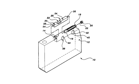
Figure 1 illustrates an exploded view of a fluid collection cassette of the
present invention;
Figure 2 illustrates the fluid collection cassette of the present invention
disposed within a housing;
2 0 Figure 3 illustrates an exploded view of a fluid collection cassette of
another
embodiment of the present invention;
Figure 4 illustrates the fluid collection cassette of Figure 3 disposed within
a
housing;
CA 02274765 1999-06-08
WO 99/20323 PCT/US98/21119
Figure 5 illustrates another embodiment of a fluid collection cassette of the
present invention; and
Figure 6 illustrates yet another embodiment of a fluid collection cassette of
the
presentinvention.
5
Detailed Description of the Preferred Embodiment
Referring to the accompanying drawings in which like reference numbers
indicate like elements, Figure 1 shows an exploded view of a fluid collection
cassette
shown generally at 10 of the present invention. Fluid collection cassette 10
comprises
a main body portion 12, an inlet tube barb 14, an outlet tube barb 16, outlet
tube
portion 18, and outlet tube adapter 20.
Preferably, main body portion 12, inlet tube barb 14, outlet tube barb 16 and
outlet tube portion 18 are integrally molded. Outlet tube adapter 20 is
provided with a
stem 22 which is press fit into outlet tube portion 18. Alternatively, outlet
tube
adapter 20 may be provided with a stem 22 which is threaded (not shown) to
mate
with matching threaded portion (not shown) of outlet tube portion 18.
A reflux bulb, shown generally at 26, comprises first end shown generally at
28 located in first body portion shown generally at 30, second body portion
shown
generally at 32, third body portion shown generally at 34, and second end
shown
2 0 generally 36 located in third body portion 34. At a first predetermined
location shown
generally at 38 on fluid collection cassette 10, a first material 40 is
disposed on fluid
collection cassette 10. At a second predetermined location shown generally at
42, a
second material is disposed on fluid collection cassette 10.
CA 02274765 1999-06-08
WO 99120323 PCT/US98/21119
6
Preferably, first material 40 and second material 44 are both metal strips,
metal circles, or other geometric shape made from metal to permit use in
connection
with a capacitive proximity switch. Alternatively, first and second materials,
40, 44,
are of a material which would permit an alternate type of sensor to determine
the
existence or non-existence of first material 40 and second material 44 at
first
predetermined location 38 and second predetermined location 42, respectively.
First material 40 and second material 44 may be disposed in fluid collection
cassette 10 (discussed in further detail below) which would raise the
manufacturing
cost, but would provide a greater guarantee of overall integrity. When first
material
40 and second material 44 are both disposed on fluid collection cassette 10,
preferably
by adhesive, there is always some chance that one of the materials, 40, 44,
could
become disassociated from fluid collection cassette 10. Indeed, as shown in
Figures 1
and 2, first material 40 has only a portion thereof adhesively fixed to
cassette 10, with
the remaining portion freestanding. Second material 44 is similary situated as
shown
in Figure 1, although the view of Figure 2 does not permit a clear showing of
the
freestanding aspect.
As Figure 1 shows in exploded view, it is clear that the hole 54 defined by
reflux bulb 26 extends through the length of reflux bulb 26. These holes are
pushed
onto and held by inlet tube barb 14 and outlet tube barb 16.
Reflux bulb 26 may assume a square cross-section measuring 5/16 (five-
sixteenth) inch on each side.
In operation, as shown in Figure 2, fluid collection cassette 10 is disposed
within housing 56. Housing 56 is located within an ophthalmic microsurgical
system.
Attached to housing 56 is a first sensor S 8 and a second sensor 60. First and
second
CA 02274765 1999-06-08
WO 99/20323 ~ PCT/US98/21119
7
sensors, 58-60, are preferably capacitive proximity switches and may be
obtained
readily from many electrical equipment manufacturers such as Balluff, Inc. of
Florence, Kentucky. However, first and second sensors, 58-60, may also be of
the
sonic type (and the materials, 40, 44, respectively, suitable for reflecting
sonic waves),
or may be of the light (LED, laser, etc.) type (and the materials, 40, 44,
respectively,
suitable for reflecting light waves.
In operation, first and second sensors, 58-60, form the first side of a
capacitor,
respectively, and first and second materials, 40, 44 form the second side of a
capacitor, respectively. Alternatively, first and second sensors, 58-60, emit
a signal
such as light, a radio ~equency, or some other frequency that his reflected
back from
first and second materials 40, 44, and sensed by sensors 58 - 60. Accordingly,
first
and second sensors, 58-60, can sense the existence or non-existence of first
material
40 and second material 44. The existence or non-existence information is
communicated from each sensor 58-60 to a controller which can act on this
information and either enable or disable the operation of the ophthalmic
microsurgical
machine, using a logical well known in the art.
Figures 3 and 4 illustrate an alternative embodiment of the present invention
in
which the first predetermined location 38 of first material 40 is at a
different location
than that indicated in Figures 1 and 2. Similarly, Figures 3 and 4 illustrate
second
2 0 predetermined location 42 of second material 44 is placed at a different
location than
that indicated in Figures 1 and 2. Further, first material 40 and second
material 44 of
Figures 3 and 4 are round disks geometrically, as opposed to arch-shaped disks
suggested in Figure 1. Because of the different locations in Figures 3 and 4,
the
CA 02274765 1999-06-08
WO 99/20323 PCT/US98/21119
8
location of first sensor 58 and second sensor 60 have also been moved
consistent with
the location of first predetermined location 38 and second predetermined
location 42.
Figure 5 illustrates another alternative embodiment which illustrates that
first
material 40 may be embedded or encapsulated within the wall of fluid
collection
cassette 10.
Figure 6 illustrates yet another alternative embodiment which illustrates that
first material 40 may be disposed inside fluid collection cassette 10. Thus,
when
disposing a material to be sensed "in" a predetermined location on the fluid
collection
cassette, the term "in" can mean "within" the wall of cassette 10 or "inside"
cassette
Z O itself.
In view of the foregoing, it will be seen that the several objects of the
invention are achieved and other advantages are attained. The embodiments were
chosen and described in order to best explain the principles of the invention
and its
practical application to thereby enable others skilled in the art to best
utilize the
invention in various embodiments and with various modifications as are suited
to the
particular use contemplated. As various modifications could be made in the
constructions and methods herein described and illustrated without departing
from the
scope of the invention, it is intended that all matter contained in the
foregoing
description or shown in the accompanying drawings shall be interpreted as
illustrative
2 0 rather than limiting. For example, the predetermined locations, 38 and 42,
are not
required to be on the same side of reflux bulb 26. Another modification
falling within
the scope of the present invention involves using three or more predetermined
locations in conjunction with the application of sensing material at each
location to
assist in identifying a function other than anterior or posterior. Another
modification
*rB
CA 02274765 1999-06-08
WO 99/20323 PCT/fJS98/21119
is that first and second materials may be the same material. Thus, the breadth
and
scope of the present invention should not be limited by any of the above-
described
exemplary embodiments, but should be defined only in accordance with the
following
claims appended hereto and their equivalents.