Note: Descriptions are shown in the official language in which they were submitted.
Method of producing moldings
Specification
Reference to related applications
The present application claims the priority of the German patent application
196 51
879.2, filed on the 13.12.1996, whose disclosed content is hereby expressly
also
made the subject matter of the present application.
Technical Field
The invention relates to a method of producing moldings in accordance with the
preamble of claim 1.
Under the term "cross-section of flow" is understood the cross-section
actually
flowed through by the plasticisable substance during the injection process,
per
section of the mold cavity. The cavity of the mold includes all the cavities
of the
mold through which the plasticisable material flows as it is injected, i.e. if
necessary
also the spree.
Prior art
Underlying the preamble is a method which, among experts, may be equated with
injection-stamping. This comparison is apt if, before the injection of the
plasticisable substance, the mold is closed apart from a gap, the
plasticisable
CA 02274850 1999-06-11
2
substance is completely injected into this gap and the gap is then closed,
injection-
stamping the molding. Basically there is also the possibility, during the
injection
process, of opening the already closed mold again or reducing the force
already
applied for keeping the mold closed. This method is used in order to
manufacture
e.g. thin walled parts such as CDs, since there are here occasionally
difficulties in
pressing by a normal injection process the plasticisable substance into the
last
corners of the mold cavity.
After the injection of the plasticisable substance, the latter is cooled in
order to
shape the molding. In this cooling phase, there are inevitably contractions of
the
substance, such as e.g. a liquid plastic, which are normally compensated for
by a
holding pressure phase with the aid of the plasticising screw. To this end,
the
plasticising screw is held under pressure during the holding pressure phase to
correspond with a pre-determined profile. Typically this pressure profile is
such
that after the change from the injection phase into the holding pressure
phase, the
highest holding pressure is set in order then to become smaller and smaller
towards
the end of the holding pressure phase. The course of the pressure profile is
derived
from the material-dependent course of the volume contraction as a result of
pressure and temperature according to the typical pVT diagram for each
material
during the cooling phase.
2 0 These processes for the shaping of standard moldings are sufficiently well-
known;
however problems arise if the mold part has regions with a different cross-
section of
flow, such that notches or sprues seal in the cooling phase so early that the
holding
pressure cannot be maintained in a controlled n~anaer in this region.
CA 02274850 1999-06-11
i
i , , . ~. DL
Altered page - 2a
From DE-As 1 I 27 579 is known a way of so altering the holding pressure of
the
plasticising cylinder initially that, although the substance is injected into
the open
mold, the latter is then closed during the injection process, this being
intended to
ensure that constantly so much material continues to be injected fi~om the
plasticising cylinder that the nozzle does not close. It is essential here
that the mold
is completely closed towards the end of the injection process. Furthermore,
I adjustable holding pressure is to be applied from the nozzle in known
fishion;
however, control of the holding pressure from the closing side of the mold
does not
come about, such that there is no overlaying of a controlled holding pressure
inside
the injection mold.
From the Japanese disclosure document 58 008622 is known a way of injecting
material into a mold cavity via an injection molding unit. The injection
itself comes
about with the mold closed. A portion of the mold wall is movable, however,
such
that, after holding pressure has been applied, the size of the mold cavity can
still be
influenced. The holding pressure is applied, however, by the injection molding
unit.
There is no mention of control of the holding pressure both on the injection
molding
2 0 side and by the movable part within the injection mold.
From EP 348 129 A2 is known a way of generating a vacuum in the injection mold
before the injection process. The material is then injected with a sudden
pressure
increase, such that there is no premature hardening even on the surface. The
nozzle
CA 02274850 1999-06-11
-.
is then closed and adjustment of the holding pressure only occurs on the mold
closing side. The mold cavity is not affected by holding pressure from both
sides.
CA 02274850 1999-06-11
3
'i
From DE-U 88 06 805 is known an injection mold in which an additional movement
of the tool is derived from the closing movement. This movement comes about
shortly before cooling and thus before the molding has completely or partially
sealed. Here a gap in the injection mold is reduced in size and the material
is
pressed from the middle into two mold cavities at the edge. In addition, this
i movement can also come about through a separate pressure means. This is thus
able to be equated with injection-stamping, without the holding pressure being
controlled by this means.
Summary of the invention
Proceeding from this state of the art, the purpose underlying the invention is
to
make possible, in the holding pressure phase, reliable distn'bution of the
holding
pressure even on complicated parts.
This object is fulfilled by a method with the features of claim I .
In this method, the contraction of the plasticisable material is realized even
in the
thick-walled region of the mold cavity, which can no longer be reached after
the
sealing of the regions having a low cross-section of flow, in that the
contraction of
the molded part is compensated for at least in these regions by a controlled
volume
adjustment of the mold cavity by means of the mold closing unit. In the other
regions, which may be reached. by the holding pressure built up b~ the
injection
2 0 molding unit; the contraction of the molded part is compensated for by the
injection
molding unit, if necessary in conjunction with the mold closing unit or the
pressure
means. By this means, individual regions of the molding can be targeted
specifically
CA 02274850 1999-06-11
4
in respect of the holding pressure, the possibility also existing in principle
of letting
the holding pressure take a different course in different regions and by this
means,
with a gradual reduction of the holding pressure, inner tensions occurring in
the
molded part through material displacement in too cold a melting are avoided.
The
only pre-requisite for this is that both the injection molding unit may be
adjusted in
respect of the holding pressure and the volume alteration of the mold cavity
may be
adjusted in respect of the force that is necessary to do this.
The units effecting the holding pressure can generate, independently of one
another,
a common pressure or force profile. The holding pressure is thus controlled by
co-
operation between the injection molding unit and the mold closing unit and if
necessary a separate pressure means according to claim 2. In an extreme case,
it is
also possible actively to relieve the stress on the mold cavity e.g. by
withdrawing
the screw. If the molded part has regions close to the spree, which lie
between the
spree and the regions remote from the spree, it does not cause any damage if
the
region close to the spree seals before the holding pressure has been
correspondingly
built up and reduced in the regions remote from the spree. In the regions
remote
from the spree, the holding pressure can be controlled by the mold closing
unit.
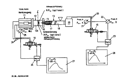
Short description of the figures
Fig. 1 A diagrammatic view of an injection molding machine with associated
2 0 control possibilities, '
Fig. 2 a flow chart for screw-dependent stamping of the molding,
CA 02274850 1999-06-11
5
Fig. 3 a flow chart for filling the mold cavity in dependence on the mold
path, as
well as
Fig. 4 a schematic view of a molding acted on according to the method,
Fig. 5 a view according to Fig. 4 with additional injection-stamping.
Detailed description of preferred embodiments
The invention is now explained in greater detail by way of example with
reference
to the attached drawings. However, the embodiments are just examples which are
not intended to limit the inventive concept to a specific physical
arrangement.
The method is used for producing moldings which are manufactured on an
injection
molding machine for processing plasticisable substances. As plasticisable
substances can 6e considered plastics, powdery _substances or even ceramic
substances. The method can be carried out basically on any injection molding
machine; however reference is made below to the structure of a plastics
injection
molding machine shown in the drawings.
An injection molding machine of this type has, according to Fig. 1, a mold
closing
unit 11, which normally receives a mold 12 between its mold carriers. The mold
12
consists, as per the embodiment given by way of example, of two parts 12b,
which
.
enclose between them, in the closed state, a mold cavity 10. The mold cavity
is
accessible from outside via a spree 14, through which the plasticisable
substance,
2 0 such as e.g. a plasticised thermo-plastic plastic, can reach the mold
cavity. The
CA 02274850 1999-06-11
6
plasticisable substance is plasticised in a plasticising cylinder 18 of an
injection
molding unit 13, preferably by a feed screw 17 configured as the feeding
means, and
led to the sprue channel in a correspondingly metered amount.
At the beginning of the shaping operation, the mold closing unit 11 transfers
parts
12b of the mold 12 into a position in which the complete clamping force,
necessary
for the production of the molding, is not yet applied, indeed if necessary no
such
force is yet applied. The plasticised substance is injected into the mold thus
closed
or almost closed, by the injection molding unit, into the mold cavity 10. Once
the
plasticised substance has been injected, the necessary locking force to
produce the
molding is applied. Thus the mold is first of all filled and now the
plasticised
substance has to be cooled so that the molding 12 can be formed.
In order to counteract any contraction of the molding during cooling,
controlled
holding pressure is applied by the injection molding unit 13. To this end, the
injection unit 19 of the injection molding unit 13 is triggered via a control
valve 1 S.
The control valve I S is col~neeted t4 the two cylinder cavities of the
injection unit
19 via two lines, whilst the two further lines are connected on the one hand
with a
pressure source (connection P) and on the other hand with a tank (connection
T) to
recirculate a hydraulic medium. In the two lines 20, which lead to the
injection
molding unit 13, pressure sensors 2I, 22 are provided which record the actual
2 0 pressure values P~~~ P~,,B in the two lines 20. The pressure difference of
the
actual pressure values thus determined corresponds to a pressure or a force
which
the feed screw exerts on the mold cavity I0. The actual pressure values are
notified
to a regulator 23, which adjusts the pressure according to a graph of desired
pressure 28 to pre-determined desired pressure values PS. Naturally, with an
CA 02274850 1999-06-11
electrically driven injection molding unit, similar values are produced in a
different
manner, as is common knowledge to the expert.
At the same time, however, the holding pressure is also influenced in a
controlled
manner by an alteration in the volume of the mold cavity 10, e. g. on the
closing side
of the mold by the mold closing unit 11. This acts particularly but not
exclusively
on regions l0a of the mold cavity, remote from the sprue _ and having a large
cross-
section of flow, and the corresponding regions of the molding which would
otherwise be cut off from the holding pressure applied by the injection
molding unit
by regions lOc of the mold cavity which have a small cross-section of flow
sealing
premaxurely. To this end, the mold closing unit is provided with hydraulic
medium
from a control valve 16 via Iines 24. This control valve is also connected on
the one
hand with a pressure source (connection P) and on the other hand with the tank
(connection T). Via a pressure sensor 25, preferably a mold inner pressure
sensor,
the actual pressure value P~t~mold, which bears on the mold is measured which
corresponds to the force for holding the mold closed. The actual value is
notified to
a controller 26, which tracks from the actual value a desired force value PF
in
accordance with the graph of desired force or desired pressure 27. Instead of
applying the volume change only via the mold closing unit, this can come about
together with some other pressure means such as a stamping die 30, which may
be
2 0 adjusted separately and independently from the mold closing unit.
Through the controlable injection molding unit in conjunction with the mold
closing
unit which can be adjusted in respect of the clamping force, from both sides
controlled holding pressure can be exerted in a defberate manner also on
different
regions of the mold cavity 10. The actual holding pressure values on the
molding
CA 02274850 1999-06-11
8
can of course be measured also by mold inner pressure sensors, as indicated
optionally in Fig. 1 by the reference used with P/P~~ ~~;~,~. In these cases,
adjustment is again made at the control valves I5, I6.
If the holding pressure has been lowered in a controlled manner at least in
regions
l0a remote from the spree and having a large cross-section of flow, through
the
application of a controlled clamping force by means of the form closing unit
11, the
molding can be removed tom the mold. In Fig. 4 is shown a mold cavity IO which
can be influenced by a corresponding two-sided control of the holding
pressure.
The molding produced in this mold cavity is e.g. a compact disc, the region
IOc
representing the CD. Proceeding from the central spree 14, first of all a
region l Ob,
close to the spree and having a large cross-section of flow, is provided which
merges via. a region IOc, close to the spree and having a low cross-section of
flow,
into the region 10a, remote from the spree and again having a large cross-
section of
flow. If such a part is produced in the known method according to prior art,
the
region lOc seals so early that holding pressure cannot be applied correctly
any more
in the region l0a remote from the spree. The plasticisable substance led into
the
mold cavity 10 via the spree 14 is therefore influenced as far as the region
lOc,
close to the spree, by the injection molding unit 13 with a controlled holding
pressure. Thus the thick-walled region l Ob, close to the sprue, is influenced
by the
2 0 injection molding unit 13 in respect of the holding pressure, the holding
pressure PS
being set. In the region I Oa, remote from the sprue, on the other hand, the
holding
pressure applied by the injection molding unit no longer has any influence.
For this
reason, the holding pressure is applied there by adjusting the clamping force
via the
mold closing unit 11 in the form of holding pressure PF.
CA 02274850 1999-06-11
9
'i
The injection itself comes about in such a way that either a gap S (Fig. 1 )
is injected
into, which is closed after or during the injection process. This can e.g.
come about
in that the mold is not completely closed or is only closed as far as a
certain force
region e.g. below the maximum clamping force. Or there is the possibility of
opening the already closed mold again through the injection pressure as the
plasticised material is injected, the parts 12b of the mold 12 moving away
firom one
another again. If no opening comes about in this way, during the injection
process
at least the clamping force which is not yet completely applied can be
reduced. If
then the clamping force needed to produce the molding 10 is applied, the
deformation here occurring leads to a process which is comparable with
injection-
stamping. A corresponding method sequence is shown in Fig. 2.
In step S 1, the mold is closed as far as a coining gap ds. Thereafter, in
step S2, the
injection of the plasticised substance is started. If the feed screw 17
reaches a
certain injection stroke mark according to the enquiry in step S3, the mold is
closed
in step S4. At this point, the two possibilities for adjusting the holding
pressure
come into play. On the side of the injection molding unit, in step S5, the
course of
the holding pressure is adjusted in controlled fashion. On the closing side of
the
mold, a program of the clamping force is started as per step S6. If both
programs
have finally led to a lowering of the holding pressure, after cooling has
occurred,
2 0 the mold is opened in step S7 and the part can be removed from the mold in
step
S8.
Alternatively, however, there is also the possibility that once, during the
closing
movement, the moveable half of the mold 12 has covered a certain pre-
determined
path, the injection process is started. Fig. 3 represents a corresponding
method
CA 02274850 1999-06-11
10
sequence, in which steps comparable with the preceding method sequence as per
Fig. 2 are provided with the same reference numbers. The method sequence
starts
with the process " mold close " as per step S9. I~ during the closing of the
mold, a
specific clamping unit stroke mark is reached shortly before the mold closes
or with
a Iow clamping force as per step S 10, the injection process as per step S 1 I
is
started. At this point, the two holding pressure closed loop controls in the
form of
the holding pressure on the side of the injection molding as per step SS and
in the
form of the program of the clamping force on the side of the mold closing as
per
step S6 come into play again. After the adjustment of the holding pressure has
ended, the mold can then be opened again in step S7 and the part can be
removed
from the mold in step S8.
The advantage of this variant is that the time needed for positioning the mold
closure can be saved.
Preferably the necessary volume of the plasticised substance for filling the
mold
cavity is not injected completely during the injection process and a pad of
the
substance can be provided in front of the screw for later adjustment. The
lowering
of the holding pressure comes about on the side of the mold closing by
reducing the
maximum clamping force.
When the volume of the mold cavity 10 is changed, the connection between the
2 0 regions 10a, having a large crass-section of flow, and the regions 1 Oc,
having a
small cross-section of flow, can be interrupted at flue same time as a result
of the
path ds (Fig. 5) of the mold necessary for this, which is the equivalent of a
stamping
of the notches or sprees.
CA 02274850 1999-06-11
11
In Figs. 2 and 3 are given the possibilities, shown in boxes in broken lines
there, of
opening or closing the mold according to the program as an alternative on the
mold
closing side to the program for the locking force as per step S6. This can
come
about e.g. in that the parts 12b of the mold 12 are moved away from one
another
during the injection process as a result of the injection pressure and
thereafter the
coining gap 8 occurring in Fig. 1 or ds in Fig. 5 is closed again under the
influence
of the mold closing unit I I. -
Fig. 5 makes clear finally that the parts can be driven together as far as a
stamping
gap ds; the movement which then occurs during injection stamping can also be
used
to interrupt simultaneously the connection between the regions 10a, having a
large
cross-section of flow, and in the region l Oc with a low cross-section of
flow.
Likewise, different regions of a mold cavity can also form different moldings,
which
are subjected to different holding pressure profiles on the injection molding
side and
on the mold closing side.
It goes without saying that this specification can be subjected to the most
different
modifications, alterations and adaptations which are within the range of
equivalents
to the pending claims.
CA 02274850 1999-06-11