Language selection

Search

Patent 2275067 Summary

Third-party information liability

Some of the information on this Web page has been provided by external sources. The Government of Canada is not responsible for the accuracy, reliability or currency of the information supplied by external sources. Users wishing to rely upon this information should consult directly with the source of the information. Content provided by external sources is not subject to official languages, privacy and accessibility requirements.

Claims and Abstract availability

Any discrepancies in the text and image of the Claims and Abstract are due to differing posting times. Text of the Claims and Abstract are posted:

  • At the time the application is open to public inspection;
  • At the time of issue of the patent (grant).
(12) Patent Application: (11) CA 2275067
(54) English Title: TRENCH-FILLING METHOD AND DEVICE
(54) French Title: METHODE ET DISPOSITIF DE REMPLISSAGE D'UN FOSSE
Status: Deemed Abandoned and Beyond the Period of Reinstatement - Pending Response to Notice of Disregarded Communication
Bibliographic Data
(51) International Patent Classification (IPC):
  • E02F 5/12 (2006.01)
  • E02F 5/22 (2006.01)
  • E02F 7/02 (2006.01)
  • E02F 7/06 (2006.01)
  • E02F 9/02 (2006.01)
(72) Inventors :
  • LAURINI, MARCO (Italy)
  • LEBAIGUE, ALAIN (Italy)
(73) Owners :
  • OFFICINE MECCANICHE LAURINI LODOVICO & C. S.N.C.
(71) Applicants :
  • OFFICINE MECCANICHE LAURINI LODOVICO & C. S.N.C. (Italy)
(74) Agent: ROBIC AGENCE PI S.E.C./ROBIC IP AGENCY LP
(74) Associate agent:
(45) Issued:
(22) Filed Date: 1999-06-17
(41) Open to Public Inspection: 1999-12-19
Examination requested: 2004-01-27
Availability of licence: N/A
Dedicated to the Public: N/A
(25) Language of filing: English

Patent Cooperation Treaty (PCT): No

(30) Application Priority Data:
Application No. Country/Territory Date
98 07 770 (France) 1998-06-19

Abstracts

English Abstract


A method for filling a trench (14), involving (i) towing with the aid of a
hydraulic shovel (1) parallel to trench (14) a frame (3) mounted on wheels
or crawlers (4) which supports a loading hopper (12) fitted with a grid (16)
in the bottom; (ii) filling the said hopper (12) with filling material with
the
aid of hydraulic shovel (1); (iii) transferring the filling material by
gravity
through grid (16) onto a vibrating screen installed beneath hopper (12),
and then onto a continuous conveyor (17) installed beneath the vibrating
screen on frame (3), transversely to its direction of movement, the
vibrating screen and the conveyor being driven by motor systems fitted to
the frame; and (iv) tipping the backfill material laterally into trench (14)
with the aid of the conveyor.


Claims

Note: Claims are shown in the official language in which they were submitted.

-7-
CLAIMS
1) Method for filling a trench (14), specifically with backfill material
excavated from the same trench, which said method involves (i) towing
with the aid of a hydraulic shovel (1) parallel to trench (14) a frame (3)
mounted on wheels or crawlers (4) which supports a loading hopper (12)
fitted with a grid (16) in the bottom; (ii) filling the said hopper (12) with
filling material with the aid of hydraulic shovel (1); (iii) transferring the
filling material by gravity through grid (16) onto a vibrating screen
installed
beneath hopper (12), and then onto a continuous conveyor (17) installed
beneath the vibrating screen on frame (3), transversely to its direction of
movement, the vibrating screen and the conveyor being driven by motor
systems fitted to the frame; and (iv) tipping the backfill material laterally
into trench (14) with the aid of the conveyor.
2) Device suitable to be towed, designed for screening filling material and
tipping it into a trench (14), and destined to be used in the method
according to claim 1, the said device being characterised in that it
comprises:
~ a frame (3) mounted on wheels or crawlers (4) and equipped with at
least one coupling (8) which connects it to a hydraulic shovel suitable
to tow it
~ a filling material loading hopper (12) on the said frame, the said hopper
being fitted with a grid (16) at the bottom
~ a vibrating screen (19) below grid (16)
~ a continuous conveyor (17) below the said vibrating screen, one end of
which conveyor projects laterally from frame (3)

-8-
~ and systems designed to drive the said vibrating screen and conveyor
(17), which said systems are fitted to the frame.
3) Device as claimed in claim 2, characterised in that conveyor (17) can
traverse under the action of a dual-action cylinder, so that it can project
from either side of frame (3).
4) Device as claimed in claim 3, characterised in that conveyor (17) is
driven by a reversing motor.
5) Device as claimed in any of claims 2 to 4, characterised in that the
coupling which connects the frame to the hydraulic shovel is a tow-bar (8)
jointed to frame (3), the position of which said tow-bar can be adjusted
with the aid of control systems (5, 6, 7) such as levers and cylinders.
6) Device as claimed in any of claims 2 to 5, characterised in that the
frame is fitted at both ends with a system which makes it integral with a
coupling (8) that connects it to the hydraulic shovel.
7) Device as claimed in any of claims 2 to 6, characterised in that the
hopper (12) is fitted to swivel in relation to frame (3) under the action of
control systems such as at least one cylinder.
8) Unit designed to fill a trench (14), characterised in that it comprises a
hydraulic shovel (1) and a screening and backfill tipping device (2) as
claimed in any of claims 2 to 7, the said device (2) being coupled to the
hydraulic shovel by means of a connector such as a tow-bar (8), so that it
can be towed by shovel (1).

Description

Note: Descriptions are shown in the official language in which they were submitted.


CA 02275067 1999-06-17
-1-
TRENCH-FILLING METHOD AND DEVICE
This invention relates to a trench-filling method and a device designed to
implement the said method.
Pipelines are used to transport fluids such as gas or oil over long
distances, and are generally protected by burying them in trenches. These
trenches are usually filled with screened backfill, and for this purpose a
screening and filling device is generally used which is fitted laterally to a
tractor that moves along the trench.
1 o A screening and filling device of this kind usually comprises a hopper
designed to receive the materials used for filling, a continuous conveyor
installed below the hopper, and a system of vibrating screens fed by the
continuous conveyor which fill the trench with successive layers of
material with a given particle size. The assembly is integral with a frame
which is suspended over the trench to be filled by the carrying arm of a
tractor or similar device. A trench can thus be filled with different layers
of
the same material or materials with different particle sizes, possibly by
making a number of runs with the device.
A device of this kind is described in detail, for example, in US patent no. 4
955 756, but numerous variations also exist on the market; the Applicant
itself has designed various improvements to a device of this kind, which
are described in its European patent application no. 0 709 526.
These devices are wholly satisfactory, but relatively expensive because
they are self-propelled.
The frame also presents the drawback that it is suspended from the

CA 02275067 1999-06-17
-2-
tractor.
Finally, the hopper must be filled with the backfill material with the aid of
a
device independent of the filling system.
To remedy these drawbacks, this invention does not use a self-propelled
filling system but a screening and filling system towed by a hydraulic
shovel of conventional type which also fills the screening device with filling
material, in which the hydraulic shovel/screening device assembly can
move either along the spoil ridge alongside the trench or along a track laid
on the other side of the trench.
The invention therefore relates primarily to a method for filling a trench,
specifically with the spoil excavated from the said trench; the said method
involves (i) towing parallel to the trench, with the aid of a hydraulic
shovel,
a frame mounted on wheels or crawlers which supports a filling hopper
fitted with a grid at the bottom; (ii) filling the said hopper with filling
material with the aid of the hydraulic shovel; (iii) transferring the filling
material through the grid by gravity onto a vibrating screen installed under
the hopper, then onto a continuous conveyor installed under the vibrating
screen on the frame, transversely to its direction of movement, the
vibrating screen and the conveyor being driven by motor systems fitted to
the frame; and (iv) tipping the filling material laterally into the trench
with
the aid of the conveyor.
The invention also relates to a device suitable for towing destined to be
used in the method described above, which screens filling material and
tips it into a trench, the said device being characterised in that it
comprises:

CA 02275067 1999-06-17
-3-
- a frame mounted on wheels or crawlers and fitted with at least one
coupling connecting it to a hydraulic shovel suitable to tow it
- a filling hopper for backfill material, fitted with a grid in the bottom,
mounted on the said frame
- a vibrating screen below the said grid
- a continuous conveyor below the said vibrating screen, one end of
which said conveyor projects laterally from the said frame
- and systems fitted to the said frame which drive the vibrating screen
and conveyor.
1 o The coupling that connects the frame to the hydraulic shovel can be a
simple tow-bar jointed at one end to the frame and at the other end to the
hydraulic shovel.
The hopper is preferably mounted so that it swivels in relation to the
frame, at least one cylinder being fitted to the frame to straighten the
hopper by swivelling it in relation to the frame, in order to discharge the
largest parts of the filling material which do not pass through the grid.
The grid can be constituted by simple parallel bars, which could be
installed, for example, parallel to the direction of movement of the device.
The conveyor is preferably installed transversely to the direction of
movement of the frame under the action of the hydraulic shovel with which
it is integral. This conveyor can advantageously traverse under the action
of a dual-action cylinder, so that it can project as required from either the
left- or the right-hand side of the device. In addition, it is driven by at
least
one reversing motor, such as a hydraulic motor, so that it can tip the filling
material to the right or left of the device.

CA 02275067 1999-06-17
-4-
Finally, the invention relates to a trench-filling assembly characterised in
that it comprises a hydraulic shovel and a device for screening and tipping
filling material of the type described above, the said device being
connected to the hydraulic shovel by a coupling such as a tow-bar, so that
it can be towed by the shovel.
The frame of the screening device will preferably be fitted at both ends
with systems that allow it to be coupled to the hydraulic shovel, so that it
can be towed from either end.
Other characteristics and advantages of the invention will appear more
clearly from the following detailed description of a form of embodiment
thereof. The said description will refer to the annexed schematic drawings
in which:
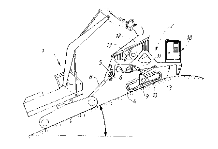
~ Figure 1 is a lateral elevation of an assembly constituted by a
hydraulic shovel and a screening and filling device towed by the said
shovel, the said assembly being shown in a position in which the
shovel is moving down a slope
~ Figure 2 is a similar view to figure 1, shown in a position in which the
shovel is moving uphill
~ Figure 3 is a cutaway view from above of the screening and filling
device towed by the hydraulic shovel
~ Figure 4 shows the position of the said screening and filling device on
uneven ground, in a lateral position in relation to the trench to be filled
In these drawings, the self-propelled hydraulic shovel is marked 1, while
the screening and filling device towed by the said shovel is marked 2.
Shovel 1 can be of any known type.

CA 02275067 1999-06-17
-5-
Device 2 comprises a frame 3, shown here mounted on crawlers 4,
although it could equally well be mounted on wheels; a tow-bar 8 is jointed
at one end by levers 5 and 6 to the said frame 3, and at the other end to
the frame of shovel 1.
Lever 6 is attached to the stem of a cylinder 7 fitted to frame 3 of the
screening and filling device.
The said frame 3 is connected to structure 9, fitted with crawlers 4, by a
system of levers such as 10 which are activated by a cylinder 11, so that
they can maintain the frame in the horizontal position whatever the slope
of the terrain on which crawlers 4 rest.
A hopper 12, one end of which, adjacent to shovel 1, is fitted so that it
swivels in relation to frame 3 under the action of cylinders 13, receives the
raw materials destined to fill trench 14 from shovel 1 (see figure 4), for
example in order to bury a pipe 15 which has been laid in the said trench.
The filling materials are usually constituted by backfill from trench 4, and
it
is advisable to screen them before using them to fill the trench. For this
purpose, hopper 12 comprises a base constituted by a grid 16, here
constituted by parallel bars arranged longitudinally which are designed to
trap excessively large spoil, which can subsequently be discharged by
2o raising the hopper (see figure 2).
The material which passes through the grid falls onto a vibrating screen
19 installed below the grid, then onto a continuous conveyor 17 which is
fitted to frame 3 beneath the vibrating screen and installed transversely to
the direction of movement of the said frame.
The said conveyor 17 projects laterally from the frame above trench 14,

CA 02275067 1999-06-17
-6-
and tips the backfill material into it. Conveyor 17 is driven by two reversing
hydraulic motors fitted to frame 3. As described above, it can also be
moved transversely with the aid of a double-action cylinder so as to
project laterally from either side of the frame, so that the backfill material
can be tipped either to the left or the right of the said frame.
The various cylinders in the screening and filling device and the motors
that drive conveyor 17 and the vibrating screen are powered and activated
by a hydraulic unit 18 fitted to frame 3. All these parts are controlled from
a distance by a remote control in the cab of the hydraulic shovel, or
1 o activated by an operator at the control panel.
The invention consequently offers a simple, inexpensive means of filling
trenches, because the trench-filling device is not self-propelled but towed
by a hydraulic shovel, which also serves to feed the filling device with
backfill material.
Both ends of frame 3 are more or less identical, so that screening device
2 can be coupled to hydraulic shovel 1 by either of the said ends in order
to be towed by it.
As will be seen from figure 4, the crawlers of the screening and filling
device can adapt to very uneven terrain, and advance, for example, on
2o spoil ridge 20 of trench 14 or on a track 21 laid on the other side of the
said trench.
As will also be seen from figures 1 and 2, the hydraulic shovel/screening
and filling device assembly is able to move up or down relatively steep
slopes, with an inclination of up to 25 degrees.

Representative Drawing
A single figure which represents the drawing illustrating the invention.
Administrative Status

2024-08-01:As part of the Next Generation Patents (NGP) transition, the Canadian Patents Database (CPD) now contains a more detailed Event History, which replicates the Event Log of our new back-office solution.

Please note that "Inactive:" events refers to events no longer in use in our new back-office solution.

For a clearer understanding of the status of the application/patent presented on this page, the site Disclaimer , as well as the definitions for Patent , Event History , Maintenance Fee  and Payment History  should be consulted.

Event History

Description Date
Application Not Reinstated by Deadline 2007-06-18
Time Limit for Reversal Expired 2007-06-18
Deemed Abandoned - Failure to Respond to Maintenance Fee Notice 2006-06-19
Inactive: Abandoned - No reply to s.29 Rules requisition 2006-06-12
Inactive: Abandoned - No reply to s.30(2) Rules requisition 2006-06-12
Inactive: IPC from MCD 2006-03-12
Inactive: S.30(2) Rules - Examiner requisition 2005-12-12
Inactive: S.29 Rules - Examiner requisition 2005-12-12
Letter Sent 2004-03-15
All Requirements for Examination Determined Compliant 2004-01-27
Request for Examination Received 2004-01-27
Request for Examination Requirements Determined Compliant 2004-01-27
Inactive: Cover page published 1999-12-19
Application Published (Open to Public Inspection) 1999-12-19
Letter Sent 1999-11-24
Inactive: Single transfer 1999-11-01
Inactive: First IPC assigned 1999-08-06
Inactive: IPC assigned 1999-08-06
Inactive: Courtesy letter - Evidence 1999-07-29
Inactive: Filing certificate - No RFE (English) 1999-07-22
Filing Requirements Determined Compliant 1999-07-22
Application Received - Regular National 1999-07-22

Abandonment History

Abandonment Date Reason Reinstatement Date
2006-06-19

Maintenance Fee

The last payment was received on 2005-04-21

Note : If the full payment has not been received on or before the date indicated, a further fee may be required which may be one of the following

  • the reinstatement fee;
  • the late payment fee; or
  • additional fee to reverse deemed expiry.

Patent fees are adjusted on the 1st of January every year. The amounts above are the current amounts if received by December 31 of the current year.
Please refer to the CIPO Patent Fees web page to see all current fee amounts.

Fee History

Fee Type Anniversary Year Due Date Paid Date
Application fee - small 1999-06-17
Registration of a document 1999-11-01
MF (application, 2nd anniv.) - small 02 2001-06-18 2001-03-15
MF (application, 3rd anniv.) - small 03 2002-06-17 2002-04-15
MF (application, 4th anniv.) - small 04 2003-06-17 2003-02-20
Request for examination - small 2004-01-27
MF (application, 5th anniv.) - small 05 2004-06-17 2004-01-29
MF (application, 6th anniv.) - small 06 2005-06-17 2005-04-21
Owners on Record

Note: Records showing the ownership history in alphabetical order.

Current Owners on Record
OFFICINE MECCANICHE LAURINI LODOVICO & C. S.N.C.
Past Owners on Record
ALAIN LEBAIGUE
MARCO LAURINI
Past Owners that do not appear in the "Owners on Record" listing will appear in other documentation within the application.
Documents

To view selected files, please enter reCAPTCHA code :


To view images, click a link in the Document Description column. To download the documents, select one or more checkboxes in the first column and then click the "Download Selected in PDF format (Zip Archive)" or the "Download Selected as Single PDF" button.

List of published and non-published patent-specific documents on the CPD .

If you have any difficulty accessing content, you can call the Client Service Centre at 1-866-997-1936 or send them an e-mail at CIPO Client Service Centre.


Document
Description 
Date
(yyyy-mm-dd) 
Number of pages   Size of Image (KB) 
Representative drawing 1999-12-01 1 13
Description 1999-06-16 6 233
Abstract 1999-06-16 1 21
Claims 1999-06-16 2 72
Drawings 1999-06-16 3 73
Filing Certificate (English) 1999-07-21 1 175
Courtesy - Certificate of registration (related document(s)) 1999-11-23 1 115
Reminder of maintenance fee due 2001-02-19 1 112
Reminder - Request for Examination 2004-02-17 1 113
Acknowledgement of Request for Examination 2004-03-14 1 176
Courtesy - Abandonment Letter (Maintenance Fee) 2006-08-13 1 175
Courtesy - Abandonment Letter (R30(2)) 2006-08-20 1 167
Courtesy - Abandonment Letter (R29) 2006-08-20 1 167
Correspondence 1999-07-28 1 31
Correspondence 1999-10-31 2 75
Fees 2003-02-19 1 29
Fees 2002-04-14 1 29
Fees 2001-03-14 1 31
Fees 2004-01-28 1 29
Fees 2005-04-20 1 27