Language selection

Search

Patent 2275292 Summary

Third-party information liability

Some of the information on this Web page has been provided by external sources. The Government of Canada is not responsible for the accuracy, reliability or currency of the information supplied by external sources. Users wishing to rely upon this information should consult directly with the source of the information. Content provided by external sources is not subject to official languages, privacy and accessibility requirements.

Claims and Abstract availability

Any discrepancies in the text and image of the Claims and Abstract are due to differing posting times. Text of the Claims and Abstract are posted:

  • At the time the application is open to public inspection;
  • At the time of issue of the patent (grant).
(12) Patent: (11) CA 2275292
(54) English Title: JOINING METAL MEMBERS
(54) French Title: ASSEMBLAGE D'ELEMENTS METALLIQUES
Status: Deemed expired
Bibliographic Data
(51) International Patent Classification (IPC):
  • F16B 17/00 (2006.01)
  • B21D 39/00 (2006.01)
  • F16S 3/08 (2006.01)
(72) Inventors :
  • SAHRAMAA, KIMMO JUHANI (United States of America)
(73) Owners :
  • SAHRAMAA, KIMMO JUHANI (United States of America)
(71) Applicants :
  • SAHRAMAA, KIMMO JUHANI (United States of America)
(74) Agent: GOWLING WLG (CANADA) LLP
(74) Associate agent:
(45) Issued: 2007-11-20
(86) PCT Filing Date: 1997-12-05
(87) Open to Public Inspection: 1998-07-09
Examination requested: 2002-11-25
Availability of licence: N/A
(25) Language of filing: English

Patent Cooperation Treaty (PCT): Yes
(86) PCT Filing Number: PCT/US1997/022293
(87) International Publication Number: WO1998/029667
(85) National Entry: 1999-06-17

(30) Application Priority Data:
Application No. Country/Territory Date
08/777,036 United States of America 1996-12-30

Abstracts

English Abstract


Studs, tracks and metal members used in steel frame
panel systems are joined or attached to each other. Metal
members (1, 2) are joined to each other by the use of depending
collars (3, 4) and through holes. A tool head (11) inserted
through the collars and holes and the tool shoulder (12) exert
pressure to simultaneously bend and crimp the collar. This
technique can also be applied to truss members or to tracks
and studs so that the members are easily joined or attached
to each other. Beveled ends facilitate the alignment of collars
with the holes.


French Abstract

L'invention porte sur un procédé permettant d'assembler ou de fixer les uns aux autres des goujons, des voies ou des éléments métalliques utilisés dans des systèmes à panneaux de châssis métalliques. Des éléments métalliques (1, 2) sont fixés les uns aux autres au moyen de bagues d'attache (3, 4) et à travers des orifices. Une tête porte-outil (11), insérée à travers les bagues et les orifices, et son épaulement exercent une pression simultanée pour plier et sertir la bague. Cette technique peut également s'appliquer à des éléments à treillis, des voies ou des goujons, dont les éléments peuvent ainsi être facilement assemblés ou fixés les uns aux autres. Des extrémités en biseau facilitent l'alignement des bagues avec les orifices.

Claims

Note: Claims are shown in the official language in which they were submitted.


What is claimed is:


1. An interconnected assembly of formed metal members in
frame structures wherein the improvement comprises:

first and second members;

said first member having at least a first preformed,
circular hole;

said second member having at least a first preformed,
circular collar;

said hole surrounds said collar; and

said collar being bent and crimped onto said first
member whereby said first and second members are fastened
together.


2. The invention of claim 1 wherein one of said members is
C-shaped.


3. The invention of claim 1 wherein one of said members is
U-shaped.


4. The invention of claim 1 wherein one of said members is
a C-shaped stud and the other member is a U-shaped track.


5. The invention of claim 1 wherein said first member is a
first metal strip and said second member is a second strip
and said first strip is offset with respect to said second
strip.


6. The invention of claim 1 wherein both of said members
are C-shaped.


7. The invention of claim 1 wherein said first member has
a second hole;
said second member has a second collar;


8


said second hole surrounds said second collar; and
said second collar being bent onto said first member.


8. The invention of claim 7 wherein said first member is a
C-shaped stud and said second member is a U-shaped track.


9. The invention of claim 1 wherein said first member has
a bevel extending from the end of said member to said hole
thereby enhancing the insertion of said collar into said
hole.


10. The invention of claim 7 wherein said first member has
a bevel extending from opposite ends of said member to each
of said first and second holes thereby enhancing the

insertion of said collars into said holes.


11. The invention of claim 7 wherein said first member
defines a web and first and second flanges extending from
opposite ends of said web; and

said first hole is on said first flange and said second
hole is on said second flange.


12.The invention of claim 7 wherein said first member
defines a web and first and second flanges extending from
opposite ends of said web;
said first hole is on said first flange and said second
hole is on said second flange; and

a bevel extends from the ends of each of said flanges
to said holes thereby enhancing the insertion of said
collars into said holes.


13. An interconnected assembly of formed metal members in
frame structures wherein the improvement comprises:

first and second members;


9


said first member having a first hole and a first
preformed, circular collar;

said second member having a second preformed, circular
hole;

said second hole surrounds said collar; and

said collar being bent and crimped onto said second
member whereby said first and second members are fastened
together.


14. The invention of claim 13 wherein said second member
has a second collar;

said first hole surrounds said second collar; and
said second collar being bent onto said first member.

15. An interconnected assembly of metal members wherein the
improvement comprises:

first and second members;

said first member having at least a first preformed,
circular hole;

said second member having at least a first preformed,
circular collar;

said hole surrounds said collar;

tool means inserted through said hole and said collar;
and

said tool means causing said collar to be bent and
crimped onto said first member whereby said first and second
members are fastened together.


16. The invention of claim 15 wherein said first member has
a second hole;

said second member has a second collar;
said second hole surrounds said second collar; and
said tool means causes said second collar to be bent
onto said first member.


17. An interconnected assembly of metal members wherein the
improvement comprises:

first and second members;

said first member having a first hole and a first
preformed, circular collar;

said second member having a second preformed, circular
hole;

said second hole surrounds said collar;

tool means inserted through said second hole and said
first collar; and

said tool means causing said collar being bent and
crimped onto said second member whereby said first and
second members are fastened together.


18. The invention of claim 17 wherein said second member
has a second collar;

said first hole surrounds said second collar;

said tool means inserted through said first hole and
said second collar; and
said tool means causing said second collar to be bent
onto said first member.


19. The invention of claim 1, wherein said first member
includes a frame member having a first surface and a second
surface, and wherein said hole is defined by a first edge
connecting to said first surface, a second edge connecting
to said second surface, and a height between said first edge
and said second edge, and wherein said circular collar is
inserted from said first edge and is crimped on said second
surface.


20. The invention of claim 13, wherein said second member
includes a frame member having a first surface and a second


11


surface, and wherein said second hole is defined by a first
edge connecting to said first surface, a second edge
connecting to said second surface, and a height between said
first edge and said second edge, and wherein said circular
collar is inserted from said first edge and is crimped on
said second surface.


21. The invention of claim 15, wherein said first member
includes a frame member having a first surface and a second
surface, and wherein said hole is defined by a first edge
connecting to said first surface, a second edge connecting
to said second surface, and a height between said first edge
and said second edge, and wherein said circular collar is
inserted from said first edge and is crimped on said second
surface.


22. The invention of claim 17, wherein said second member
includes a frame member having a first surface and a second
surface, and wherein said second hole is defined by a first
edge connecting to said first surface, a second edge

connecting to said second surface, and a height between said
first edge and said second edge, and wherein said circular
collar is inserted from said first edge and is crimped on
said second surface.


23. The invention of claim 15, wherein said tool means
includes a tool head and a tool shoulder, both of which
operates together to bend and crimp said collar, and wherein

said tool head includes a plurality of head members defining
a circle, and wherein said head members are insertable
through said hole and said collar and is expandable to
change a radius of said circle.


12


24. The invention of claim 17, wherein said tool means
includes a tool head and a tool shoulder, both of which
operates together to bend and crimp said collar, and wherein

said tool head includes a plurality of head members defining
a circle, and wherein said head members are insertable
through said second hole and said collar and is expandable
to change a radius of said circle.


13

Description

Note: Descriptions are shown in the official language in which they were submitted.


CA 02275292 1999-06-17

WO 98t29667 PCT/US97/22293
TITLE
JOINING METAL MEMBERS

TECHNICAL FIELD

This invention relates to the construction industry and
particularly to steel frame panel systems and how studs,
tracks and metal members used in such systems are joined
together.

BACKGROUND OF THE INVENTION

Studs, tracks and metal members are finding widespread
use in the construction industry and particularly as part of
steel frame panel systems. To join metal members together
use is generally made of self tapping screws, nuts and bolts or,
for example, clinch pressing. An object of this invention is to
improve the way metal members are joined or attached to one
another. Another object is to have a single connecting point
which provides diagonal rigidity.
It would be desirable to have metal pieces prefabricated
with prepositioned holes and collars to eliminate or lessen the
need of manual work at a frame panel assembly station where
fabrication takes place, or at a site, thereby reducing the cost.
1


CA 02275292 1999-06-17

WO 98/29667 PCTIUS97/22293
SUMMARY OF THE INVENTION

Prepunched holes on metal members surround collars on
adjoining metal members. A tool head, inserted through both
members, pulls on the collar of one member to bend the collar
against the other member and a tool shoulder. The force of the
tool bends and crimps the collar tightly with the result that the
members are connected, fastened or joined together in a rigid
manner.
The members can be in a C-shape or U-shape or other
structural shapes and of various thicknesses or gauges, and are
applicable to tracks and studs and metal plates in general. In an
automated manufacturing process frames and trusses can be
easily prefabricated. A single crimped connection point gives
diagonal rigidity to joined members.

BRIEF DESCRIPTION OF THE DRAWINGS

Fig. 1 is a perspective view of two sheet metal pieces
prior to being joined.
Fig. 2 is an exploded view of a part of the tool used to
join the pieces.
Fig. 3 is a perspective view of the two plates joined
together.
Fig. 4 is a perspective view of a track member using the
invention.
Fig. 5 is a perspective view of multiple collars on each
2


CA 02275292 1999-06-17

WO 98/29667 PCT/US97/22293
leg of a member.
= Fig. 6 shows the use of beveled ends with through holes.
Fig. 7 is a perspective view of another metal member
having both collars and through holes.
Fig. 8 is a perspective view of two metal strips offset
with respect to each other.
Fig. 9 is a perspective view of of a slit collar used n the
invention, and
Fig. 10 is a perspective view of of a v-cut collar used n
the invention.

DETAILED DESCRIPTION OF THE INVENTION

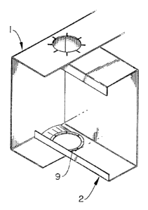
Referring to Fig. 1 the metal track in the form of a U-
shape member 1 with a web and flanges 5 and 6 to be joined to
a metal stud in the form of a C-shape member 2, as is standard
in the industry, having flanges 7 and 8. The members 1 and 2
have several different terms in the art such as member, plate,
stud, track or formed shape. The attachment could also be made
between plates, one plate corresponding to flange 6 and the
other plate corresponding to flange 8. Two through holes in
flanges 7 and 8 surround collars 3, 4 depending inwardly from
flanges 5 and 6. A suitable tool head is inserted through track
1 into the interior of stud 2, and is brought to bear against the
collars and bends and crimps the collars against the stud 2. An
' advantage of the invention is that inserting the tool in this
manner makes access easier from the outside of the member or
any member structure than if the tool head had to fed from the
3


CA 02275292 1999-06-17

WO 98/29667 PCT/US97/22293

behind the connection point in some other manner. This makes it
easier to join two members anywhere at any connecting point in
a metal construction system. This is important for an
automated system forming frame panels or trusses in formed
shape building construction systems.
The technique for joining members 1 and 2 can be applied
to any member, plate, stud, track, or any formed metal shape.
Indeed the attachment could also be made between two strips
of metal without flanges. The C-shaped member could be a top
chord, a bottom chord, or a web member in a prefabricated
truss. The top chord could serve as a roof rafter while the
bottom chord could serve as a ceiling joist. The stud can be a
wall stud or any vertical stud. When extending only a part of the
vertical height such vertical studs are referred to as a jack
stud or cripple stud.
Fig. 2 is an exploded view of a part of the tool used to
bend and crimp the collar. From the bottom, as viewed in Fig. 2,
a tool head is inserted through the hole and collar in a
compressed form as shown at 10. After passing completely
through the hole and collar it is expanded as shown at 11. The
tool head is brought to bear against the collar while the flange
of the track is in contact with tool shoulder 12. The tool head
bears against the collar and bends the collar while at the same
time a crimping action takes place at the tool shoulder. A
similar operation takes place at the other flange of the track 1.
Thus the tool head and shoulder constitute tool means to join
the members together. Viewing Figs. 1 and 2 it would be very
difficult to insert a tool from the left or right part of stud 2.
4


CA 02275292 1999-06-17

WO 98/29667 PCT/US97/22293

Using the tool shown secures access from the outside of the
member and connection point by passing through the aligned
hole and collar.
As seen in Fig. 3 the collar is bent or crimped at 9 thereby
joining a flange of track 1 to a flange of stud 2 at this single
connecting point. The action of the tool against the collars
causes them to be bent and crimped to form the joint thus
providing diagonal rigidity to the mechanical connection. While
Figs. 1 and 3 show track 1 with the depending collars and the
stud with the holes it is evident that either kind of plate could
have a collar or a through hole.
Other types of plates or members can have the same
configuration of collars and holes. Fig. 4 shows a U track with
collars 14, 15 depending inwardly thereof, and with the web
partially cut as is common with a sill track and head track.
Indeed the invention is applicable wherever metal pieces have
to be joined such as in window or door openings where there are
head tracks, sill tracks, vertical studs, and jamb studs.
Fig. 5 shows a track with four collars 20, 22, 24 and 26
depending inwardly, two on each flange of the track. Of course
there could be any number of collars in any location of a metal
member.
Fig. 6 shows yet another embodiment of the invention. A
metal stud has two through holes 30, 40. The ends of the stud
have bevels 31 and 41 tapering from holes 30, 40, respectively,
to the ends of the flanges. The bevels serve to facilitate
alignment of the through holes with the collars.
Fig. 7 shows the invention applied to a member such as is
5


CA 02275292 1999-06-17

WO 98/29667 PCT/US97/22293
commonly used in a roof truss. This figure shows both a
through hole 60 and a collar 61 in web 62. The web 62 could
have only collars when back to back with other members having
only through holes in alignment with the collars as is the case
in commonly built trusses and would be applied to top and
bottom chords, truss-web members, ceiling joists, or roof
rafters. In this kind of member assembly applications they
generally have webs that are back to back. Again the same tool
means is used to join the members.
Fig. 8 shows the invention applied to two metal members.
Here the members are metal strips. Strip 81 has collars 83, 84
while strip 82 has a hole through which collar 84 extends prior
to being bent. The two strips are offset or diagonally placed
with respect to each other. The angle the strips are offset
relative to each other can vary widely.
The collars used in Figs. 1-8 use solid collars. However
there are other collar variations possible. Fig. 9 is a perpective
view of a slit collar used in the invention. As shown a series of
vertical cuts 90 are spaced around the periphery of the collar.
The number of slits depends on the thickness of the members
involved as well as the height of the collar as these parameters
will determine the force necessary to bend and crimp the
collare as well as the strength of the resulting connections of
the joined members.
Fig. 10 is a perpective view of a v-cut collar used in the
invention. As shown a series of v-cuts 100 are spaced around
the periphery of the collar. Similar to Flg. 9 the number of v-
cuts in Fig. 10 depends on the thickness of the members
6


CA 02275292 1999-06-17

WO 98/29667 PCT/US97/22293

involved as well as the height of the collar as these parameters
will determine the force necessary to bend and crimp the
collare as well as the strength of the resulting connections of
the joined members.
The invention finds particular utility in the manufacture
of prefabricated frames and trusses. The sizes of frames and
trusses can be incorporated in an automated manufacturing
process using the crimping tool to manufacture any desired size
frame or truss. Heretofore making frames and trusses on site
by cutting, sawing, and then using rivets, screws, bolts, or
welding, to fasten metal members together is labor intensive.
The use of the disclosed collars and through holes in an
automated process saves material and labor. The tool can be
used at any connection point in the member structure and the
number of heads and shoulders the tool means is obviously a
design matter.

25
7

Representative Drawing
A single figure which represents the drawing illustrating the invention.
Administrative Status

For a clearer understanding of the status of the application/patent presented on this page, the site Disclaimer , as well as the definitions for Patent , Administrative Status , Maintenance Fee  and Payment History  should be consulted.

Administrative Status

Title Date
Forecasted Issue Date 2007-11-20
(86) PCT Filing Date 1997-12-05
(87) PCT Publication Date 1998-07-09
(85) National Entry 1999-06-17
Examination Requested 2002-11-25
(45) Issued 2007-11-20
Deemed Expired 2011-12-05

Abandonment History

There is no abandonment history.

Payment History

Fee Type Anniversary Year Due Date Amount Paid Paid Date
Application Fee $150.00 1999-06-17
Maintenance Fee - Application - New Act 2 1999-12-06 $50.00 1999-06-17
Maintenance Fee - Application - New Act 3 2000-12-05 $50.00 2000-11-27
Maintenance Fee - Application - New Act 4 2001-12-05 $50.00 2001-11-19
Request for Examination $200.00 2002-11-25
Maintenance Fee - Application - New Act 5 2002-12-05 $75.00 2002-11-25
Maintenance Fee - Application - New Act 6 2003-12-05 $75.00 2003-12-05
Maintenance Fee - Application - New Act 7 2004-12-06 $200.00 2004-11-23
Maintenance Fee - Application - New Act 8 2005-12-05 $200.00 2005-11-28
Maintenance Fee - Application - New Act 9 2006-12-05 $200.00 2006-11-30
Final Fee $300.00 2007-09-04
Maintenance Fee - Patent - New Act 10 2007-12-05 $250.00 2007-11-13
Maintenance Fee - Patent - New Act 11 2008-12-05 $125.00 2008-12-05
Maintenance Fee - Patent - New Act 12 2009-12-07 $125.00 2009-12-07
Owners on Record

Note: Records showing the ownership history in alphabetical order.

Current Owners on Record
SAHRAMAA, KIMMO JUHANI
Past Owners on Record
None
Past Owners that do not appear in the "Owners on Record" listing will appear in other documentation within the application.
Documents

To view selected files, please enter reCAPTCHA code :


To view images, click a link in the Document Description column. To download the documents, select one or more checkboxes in the first column and then click the "Download Selected in PDF format (Zip Archive)" or the "Download Selected as Single PDF" button.

List of published and non-published patent-specific documents on the CPD .

If you have any difficulty accessing content, you can call the Client Service Centre at 1-866-997-1936 or send them an e-mail at CIPO Client Service Centre.


Document
Description 
Date
(yyyy-mm-dd) 
Number of pages   Size of Image (KB) 
Abstract 1999-06-17 1 44
Drawings 1999-06-17 4 87
Representative Drawing 1999-09-10 1 7
Drawings 2003-04-10 4 133
Description 1999-06-17 7 258
Claims 1999-06-17 4 122
Cover Page 1999-09-10 1 43
Claims 2006-11-09 6 180
Claims 2006-03-01 4 111
Representative Drawing 2007-06-06 1 9
Cover Page 2007-10-19 1 39
Assignment 1999-06-17 4 135
PCT 1999-06-17 7 256
Fees 2002-11-25 1 33
Prosecution-Amendment 2002-11-25 1 33
Prosecution-Amendment 2003-04-10 1 39
Prosecution-Amendment 2003-04-10 5 171
Fees 2003-12-05 1 30
Fees 2001-11-19 1 28
Prosecution-Amendment 2006-05-09 2 81
Fees 2000-11-27 1 29
Fees 2004-11-23 1 27
Correspondence 2005-02-16 1 15
Fees 2004-12-07 6 237
Prosecution-Amendment 2005-09-16 3 93
Fees 2005-11-28 1 32
Prosecution-Amendment 2006-03-01 10 337
Fees 2006-11-30 1 37
Prosecution-Amendment 2006-11-09 10 325
Correspondence 2007-09-04 2 49
Fees 2007-11-13 1 40
Fees 2008-12-05 1 29
Fees 2009-12-17 1 200
Correspondence 2010-01-11 1 22
Correspondence 2010-02-04 1 13
Fees 2009-12-07 1 15
Fees 2010-01-13 4 78
Fees 2009-12-17 1 40