Note: Descriptions are shown in the official language in which they were submitted.
CA 02275344 1999-06-16
WO 98/27409 PCT/US97/22871
-1-
DEVICE AND METHOD FOR DETERMINING LIQUID-PROBE CONTACT
BACKGROUND OF THE INVENTION
Field of the Invention
The present invention relates to a method and apparatus for
detecting a surface of a liquid in a container, and to a method and
apparatus for use in an automated blood/piasma sampling system for
detecting a surface of a liquid in a container and for controlling a
position of a probe with respect to the surface of the liquid. More
particularly, the present invention relates to a method and apparatus
for maintaining accuracy of the liquid detection over a period of time.
An example of an automated blood/plasma sampling system for
which the present invention is applicable is disclosed, for example, in
U.S. Patent 5,236,666 to Hulette et al. The subject matter of this
patent to Hulette et al. is incorporated herein by reference. An
example of a piercing and sampling probe is disclosed in U.S. Patent
5,354,537 to Moreno. The subject matter of the patent to Moreno is
incorporated herein by reference. Another example of a sampling
probe is disclosed in U.S. Patent 5,178,019, issued January 12,
1993, to Keiter. The subject matter of the patent to Keiter is
incorporated by reference herein. An example of a liquid level sensing
probe and control circuit is disclosed in U.S. Patent 5,493,922, to
Ramey et al. The subject matter of the patents to Hulette et al., to
Moreno, to Ramey et al. and to Keiter are each assigned to the same
assignee as the present application.
' Automated sample handling systems are known which
automatically dispense fluid samples, such as blood plasma and
reagents, into a reaction well of a cuvette. Such instruments are
useful in the field of biochemical analysis for measuring blood clotting
times and for automatically carrying out chemical assays. An
CA 02275344 1999-06-16
WO 98/27409 PCT/ITS97/22871
_2_
automated sample handling system for carrying out blood and plasma
bioassays is described in U.S. Patent 5,236,666, to Hulette et al.
In this particular system, fluid samples, such as blood or
plasma, are stored in containers, such as test tubes, which are
vacuum sealed by way of a rubber septum that must be pierced in
order to withdraw a measured amount of the sample for testing
purposes. U.S. Patent 5,354,537 to Moreno, discloses an example of
a piercing and sampling probe suitable for piercing and sampling a
measured amount of liquid.
The Hulette et al. system also includes a temperature controlled
housing provided for storing fluid samples and reagents at a relatively
cool temperature for preventing degradation of the samples and
reagents prior to sample analysis. The temperature controlled housing
typically maintains the fluid samples and reagents at a temperature of
10°C. The actual analyses are generally carried out at 37°C
(98.6°F), standard human body temperature. Accordingly, it is
necessary to heat the fluid sample and reagents to 37°C prior to
analysis. U.S. Patent 5,178,019, to Keiter, discloses a sample probe
device useful for heating fluid samples and reagents prior to analysis.
~ The piercing and sampling probes in the Hulette et al. system
are raised and lowered in operation by a robotic arm which maneuvers
a probe between reagent containers and a reaction cuvette for
automatically aspirating and dispensing reagents. The surface of a
liquid, whether a sample or reagent, is detected for accurately
controlling movement of the probe. Basically, the surface of the liquid
is detected by detecting a change in capacitance of the probe with
respect to the chassis of the automated blood/plasma sampling
system.
CA 02275344 1999-06-16
WO 98/27409 PCT/US97/22871
-3-
Descriution of the Related Art
In U.S. Patent 5,493,922 to Ramey et al., a method and
apparatus are disclosed which are for a liquid level sensor control
circuit of a bioassay apparatus for controlling a position of a sampling
probe with respect to a surface of a liquid in a container. The
apparatus includes a sampling probe, an oscillator circuit coupled to
the sampling probe for producing a first output signal having a
constant frequency, a comparator coupled to the oscillator circuit for
comparing the amplitude of the first output signal to a first reference
amplitude and for producing a change signal when the amplitude of
the first output signal changes with respect to the reference
amplitude, and a controller responsive to the change signal for
controlling the position of the sampling probe with respect to the
surface of the liquid. In one embodiment in Ramey et al., a filter is
provided in communication with the oscillator circuit to servo the
oscillator output signal to a fixed level by controlling the amplitude of
the first output signal. The amplitude of the first output signal
changes in response to a capacitance change when the probe touches
the surface of the liquid.
However, when the temperature of a probe changes, or foam
or droplets of liquid adhere to the probe, the related art systems may
output a faulty indication of a liquid level. Because temperature,
foam, liquid droplets and other external factors besides the liquid body
may also influence the oscillation of the probe, these factors may also
influence the probe systems to falsely indicate the presence of liquid.
SUMMARY OF THE INVENTION
The present invention accurately senses a surface of a liquid
when a probe, such as a piercing or sampling probe, for a bioassay
apparatus touches the surface of the liquid. Over a period of time,
the accuracy of the liquid level sensing system is maintained.
CA 02275344 1999-06-16
WO 98/27409 PCT/US97/22871
-4-
The above and other objects of the invention are accomplished
by the provision of a liquid level sensor for controlling a position of a
sampling probe with respect to a surface of a liquid in a container,
including a sampling probe for touching the surface of the liquid in the
container and a probe oscillator electrically connected to the
(conductive) probe. The probe is moved mechanically to contact the
liquid in the container. The container rests on, or is in close proximity
to, a grounded conductor. When the probe contacts the liquid, the
liquid with the grounded conductor, forms a capacitor that is in
parallel with a frequency-determining capacitor on the probe oscillator.
Contact of the probe with the liquid therefore lowers the frequency of
the probe oscillator.
In the present invention, the probe/liquid detector can have its
output compared to a reference level to determine the presence or
absence of liquid wherein the reference level is changed to follow the
output of the detector. In one embodiment of the invention, it can be
determined that liquid has been contacted when a count has been
reached several times in a row (the count being a function of the
probe output and changeable). In another embodiment of the
invention, it can be determined that liquid has been contacted when a
count has been reached within a certain threshold several times in a
row, while still having the reference count change to follow the probe
output (regardless of the threshold). A digital counter can be
provided to determine the frequency of the probe oscillator. A
reference counter can also be provided to tune the count (frequency)
from the probe oscillator counter to thereby compensate for drift.
And, the adjustable detection threshold permits control of the
sensitivity by changing the parameters of the circuit.
CA 02275344 1999-06-16
WO 98/27409 PCT/US97/22871
-5-
BRIEF DESCRIPTION OF THE DRAWINGS
A preferred embodiment of the invention wilt be described in
conjunction with the accompanying drawings.
Figure 1 is a schematic block diagram of an embodiment of a
probe and a liquid sensor control circuit according to the present
invention;
Figure 2 is a perspective view of a robotic arm including a
probe and a liquid level sensor control circuit according to the present
invention; and
Figures 3, 4 and 5 are schematic block diagrams of different
embodiments of a liquid level sensor control circuit.
DETAILED DESCRIPTION OF THE INVENTION
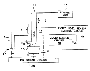
Figure 1 shows a schematic block diagram of an embodiment
of a probe for an automated blood/plasma sampling system and its
relation to a liquid sensor circuit and control circuit according to the
present invention. Robotic arm 10 maneuvers probe 11 between
reagent containers, such as reservoir 13, to a reaction cuvette (not
shown) for automatically aspirating and dispensing reagents as
described, for example, in U.S. Patent Application Serial No.
07/443,951, to Hulette et al. Robotic arm 10 raises and lowers probe
1 1 along the directions indicated by arrow 12 for taking a measured
volume of liquid from liquid reservoir 13 or dispensing it to a reaction
cuvette. Generally, probe 1 1 includes a metallic tube 14 having a
narrow tip 14a for dipping into reservoir 13 and aspirating a measured
amount of reagent. Probe 1 1 may also be adapted for piercing a
container sealed by a rubber septum to aspirate a measured volume of
liquid from the container by including a pointed tip.
As previously mentioned, it is desirable in certain applications
to heat the reagent within probe 11 while the probe is moved by
robotic arm 10 toward a cuvette where the reagent is dispensed. In
CA 02275344 1999-06-16
WO 98127409 PCT/US97/22871
-6-
these applications, probe 1 1 is provided with an optional heater 15.
Heater 15 preferably includes a coiled nichrome wire wrapped around
tube 14 and electrically connected by wires 16 to a power supply 17
which shares a common ground with chassis 18. Power supply 17
can either be a DC or AC power supply depending on the
requirements of a particular application. In order to aspirate a
measured amount of reagent from reservoir 13, it is necessary to
detect when probe 1 1 contacts the surface of the reagent. As
previously discussed, this is typically accomplished with the use of a
capacitance measuring device for detecting a change in the
capacitance of tube 14 with respect to the ground plane formed by
chassis 18 when tube 14 contacts the reagent on reservoir 13. Tube
14 presents a first capacitance CP with respect to chassis 18. When
optional heater 15 is provided, heater 15 has a common ground with
instrument chassis 18 and, therefore, is capacitively a part of chassis
18. Thus, optional heater 7 5 presents a second capacitance CH with
respect to tube 14. Liquid reservoir 13 presents an additional
capacitance C~ between probe 1 1 and instrument chassis 18. Thus,
before probe 1 1 touches the surface of the liquid, the total
capacitance CT, measured by the capacitance measuring device is
CTS = CP + CH.
If an optional heater is not provided, CH equals zero and the total
capacitance CT, is CP. After probe 1 1 touches the surface of the
liquid, the total capacitance CTZ measured by the capacitance
measuring device is
CT2 = CP ~- C~ + CH.
Detection of the additional capacitance C~ be a capacitance
measuring device indicates when probe 11 contacts the liquid surface
in container 13. However, the presence of capacitance CH caused by
an optional heater can be sufficiently large to limit the ability of the
capacitance measuring device to sense a change in C,., by C~.
CA 02275344 1999-06-16
WO 98/27409 PCT/US97/22871
_7_
The liquid sensor circuit and liquid level sensor control circuit of
the present invention reliably senses changes in capacitance between
the probe and the system chassis even in the presence of an optional
heater. In fact, the liquid level sensor system according to the
present invention reliably senses the surface of, for example, liquid
volumes less than 300 NI of saline in a plastic 3 ml reagent bottle,
even while piercing a sealing septum.
Figure 2 is a perspective view generally showing a preferred
embodiment of robotic arm 10 including a probe 11 and a liquid level
sensor control circuit according to the present invention. Probe 1 1
can be a sampling probe or a piercing and sampling probe for piercing
rubber caps used to seal medical sample collection tubes, such as
that disclosed in the previously mentioned application to Moreno.
When probe 1 1 is a piercing sampling probe, it is preferably
sharpened in accordance with the piercing probe disclosed in the
previously mentioned patent to Moreno. Moreover, when probe 1 1 is
a piercing sampling probe, it is adapted for detecting the surface of a
liquid in a container when piercing the cap of the container. Probe 1 1
senses a liquid-air interface of a conductive liquid in container 13,
such as blood or plasma, while probe 1 1 moves into container 13 for
accurately positioning probe 1 1 with respect to the surface of the
liquid.
Probe 1 1 is controllably moved into a horizontal axis 22 by lead
screw 23 driven by horizontal lead screw motor 24. Vertical
movement for raising and lowering probe 1 1 along axis 25 is provided
by gear rack 26 driven by vertical motor 27 and a pinion assembly
- (not shown). Motors 24 and 27 are each selectively controlled by
signals received from associated motor controllers, which are part of
the liquid level sensor control circuit of the present invention. Motor
controller 32, for example, is shown in the schematic block diagram
of Figure 3. Motor 27 provides sufficient torque for driving probe 1 1
CA 02275344 1999-06-16
WO 98/27409 PCT/US97/22871
_g_
through a septum of a sealed container when probe 11 is a piercing
probe. Of course, the probe could be a vertically movable probe
without any capabilities of horizontal movement, or the probe could
be capable of moving vertically as well as in a plurality of directions in
a horizontal plane. Also, if desired, the probe could be held
stationary, with the sample container being moved upwardly in the
direction of the probe.
Liquid level sensor control circuitry 30 is coupled to probe 1 1
for sensing a liquid-air interface. One portion of liquid level sensor
control circuitry 30 can be located on a printed circuit board mounted
at 29. Of course, the liquid level sensor control circuitry according to
the present invention can be located together on a single printed
circuit board.
Microcontroller 31 is a two-axis arm controller, that is,
microcontroller 31 and the two motor controllers monitor and control
the horizontal position of the rack assembly holding the probe 11 and
the vertical position of probe 1 1 with respect to the surface of a
liquid. Microcontroller 31 and motor controller 32 correlate the
position of probe 1 1 with signals received from a liquid sensor circuit
for determining the height of the liquid within the container. Flex
cables 21 couple electrical signals between various portions of the
control system according to the present invention. As previously
mentioned, probe 1 1 can be fitted with a heating coil for preheating
sampled fluids prior to dispensing into a reaction chamber.
Figure 3 is a schematic block diagram of one embodiment of a
liquid level sensor control circuit 30. Illustrated in Figure 3 are probe
1 1 and R/C or L/C probe oscillator 31. Also shown are probe counter
33, reference counter 37 and detect counter 34. A comparator circuit
36, timing logic 32 and reference oscillator 35 are also shown.
In operation, probe 1 1 changes the tuning of the R/C or L/C
probe oscillator 31 by shifting the frequency of the probe oscillator 31
CA 02275344 1999-06-16
WO 98/27409 PCT/US97/22871
-9-
down when probe 1 1 is in contact with liquid. Probe counter 33
counts the cycles of the frequency signal output by probe oscillator
31. Reference counter 37 stores an adjustable reference count.
Comparator 36 compares the probe count stored in probe counter 33
with the reference count stored in reference counter 37.
At regular intervals, timing circuit 32 controls various
operations of the probe counter 33, the reference counter 37 and the
detect counter 34, explained below. In the preferred embodiment, the
timing circuit 32 is programmable so that the regular interval may be
adjusted for different sensing operations (for example, for sensing
different types of liquid). Timing circuit 32 may constructed from any
well known hardware or hardware/software combinations which
perform the below described processes (such as a computer, a
programmable integrated circuit). Reference oscillator 35 (such as a
quartz oscillator) provides timing circuit 32 with a timing signal, such
as a square wave clock signal. The timing logic typically consists of
counters to divide the signal from the reference oscillator down to the
reference interval period, and logic to generate and synchronize the
signals needed to clock, load and clear the other components.
At the regular intervals, the reference counter 37 is adjusted by
timing circuit 32 to follow the probe count in probe counter 33. If the
contents of reference counter 37 are greater than the contents of
probe counter 33, reference counter 37 is decremented. If the
contents of reference counter 37 are less than the contents of probe
counter 33, reference counter 37 is incremented. Then, timing circuit
32 clears the probe counter 33, resetting the probe count to zero.
Additionally, in response to the timing circuit 32, at each
regular interval, the detect counter 34 counts the number of
successive times the probe count in probe counter 33 is less than the
reference count in reference counter 37. At each regular interval,
when the comparison indicates the probe count to be greater than the
CA 02275344 1999-06-16
WO 98/27409 PCT/I1S97/22871
-10-
reference count, the timing circuit 32 clears the detect counter 34,
resetting its count. When a predetermined number of successive
comparisons (sampled by timing circuit 32 at the regular interval) all
indicate the probe count is less than the reference count, detect
counter 34 outputs a liquid sensed signal, indicating that the probe 1 1
has contacted the liquid body.
In a more detailed embodiment, at every regular interval, the
detect counter 34 increments or decrements with reference counter
37. Whenever the direction of the count of detect counter 34
changes (timing circuit 32 changes increment instruction to a
decrement instruction, or a decrement instruction to an increment
instruction), the detect counter 34 is reset, zeroing its count. When
detect counter 34 decrements past a fixed count, it sets the liquid
sensed output. In this manner, the circuitry of the sensor control
circuit is simplified since the timing circuit 32 may control the
operations of reference counter 37 and detect counter 34 using the
same output signal.
According to the above described sensor control circuit, the
liquid body can be reliably detected, while slow changes to the probe
oscillator can be filtered out, such as those caused by temperature
variations or droplets of liquid or foam adhering to the probe 11.
When probe 1 1 contacts liquid, the frequency shift of probe
oscillator 31 is significant enough to cause timing circuit 32 to
decrement reference counter 37 and detect counter 34 for an
extended period of time. Thus, detect counter 34 is able to be
decrement its count successively (without being reset) until it
decrements past a fixed count (the predetermined number) and
indicates the presence of the liquid body. Because the downward
frequency shift of the probe oscillator 31 is significant when the
probe 1 1 contacts the liquid body, the probe counter 33 outputs a
significantly lower count at each regular interval. While timing circuit
CA 02275344 1999-06-16
WO 98127409 PCT/US97/22871
-11-
32 continues to decrement the reference count in reference counter
37, the reference count will not decrement past the output of the
probe counter 37 (at the end of the regular interval) for a significantly
- long time period. This allows the detect counter 34 to decrement the
predetermined number of times without being reset in order to
indicate the presence of liquid.
In contrast, when the probe 1 1 is subject to temperature
variations, liquid droplets, or foam, for example, the frequency of
probe oscillator 31 also may shift downwards (and thus the probe
count of probe counter 33 may be lower at the regular intervals).
However, because the frequency shift of the probe oscillator 31 is not
as great as when the probe 1 1 contacts the liquid body, the reference
count in reference counter 37 can succeed in decrementing past the
probe count (at the regular interval) before the detect counter 34
consecutively decrements the predetermined number of times (to
indicate the presence of liquid). Thus, the timing circuit 32 will reset
the detect counter 34 at the next reference interval since the
reference count in reference counter 37 will be less than the probe
count of probe counter 33. Therefore, the predetermined number is
never reached in the detect counter 34 and no determination of liquid
contact is made.
Figure 4 is a schematic block diagram of another embodiment
of liquid level sensor control circuit 30. Illustrated in Figure 4 are
probe 1 1 and R/C or L/C probe oscillator 31. Also shown are probe
counter 33, reference counter 37 and detect counter 34. Timing
circuit 32 and reference oscillator 35 are also shown in Figure 4,
along with zero detect 38.
In the liquid level sensor control circuit of Figure 4, in
operation, probe 1 1 changes the tuning of the R/C or L/C oscillator
31, shifting down the frequency of the signal output by probe
oscillator 31, when probe 1 1 is in contact with a liquid body. Probe
CA 02275344 1999-06-16
WO 98/27409 PCT/US97/22871
-12-
counter 33 decrements a probe count for each cycle of the frequency
of the signal output by probe oscillator 31.
Zero detect circuit 38 is coupled to the probe counter 33 to
receive the probe count of probe counter 33 as an input. When zero
detect circuit 38 detects the probe count has reached zero, zero
detect circuit 38 outputs a zero detect signal to timing circuit 32.
At regular intervals, timing circuit 32 loads probe counter 33
with a reference count stared in reference counter 37. Because
timing circuit 32 loads the reference count into probe counter 33 at
every regular interval, receipt of a zero detect signal from zero detect
circuit 38 indicates the reference count is smaller than the number of
cycles, within the regular interval, of the frequency of the signal
output by probe oscillator 31. If the reference count is larger than the
number of cycles within the regular interval, no zero detect signal will
be output by zero detect circuit 38 since the reference count will be
loaded into probe counter 33 before the probe counter 33 is able to
be decremented to zero.
In response to the receipt of the zero detect signal from zero
detect circuit 38, timing circuit 32 increments the reference count in
reference counter 37. If the zero detect signal is not received from
zero detect circuit 38, timing circuit 32 decrements the reference
count. Thus, the reference count is respectively incremented or
decremented to slowly follow the larger or smaller number of cycles
per regular interval of the signal output by probe oscillator 31.
Detect counter 34 functions in a similar manner as described
above with respect to Figure 3. Detect counter 34 counts up when
reference counter 37 counts down, and resets when reference
counter 37 counts up. When detect counter 34 reaches a
predetermined number, the output is set, indicating the presence of
liquid. In this way, the liquid sensing allows the system to
CA 02275344 1999-06-16
WO 98/27409 PCT/LTS97/22871
-13-
compensate for frequency drift in the probe oscillator, because slow
changes are followed without generating a spurious output.
Figure 5 is a schematic block diagram of a further embodiment
of liquid level sensor control circuit 30. Illustrated in Figure 5 are
probe 1 1 and R/C or L/C probe oscillator 31. Also shown are probe
counter 33, reference counter 37 and filter counter 41. Timing circuit
32 and reference oscillator 35 are also shown in Figure 5, along with
zero detect 38 and threshold detect 39 .
As in Figure 4, in Figure 5 in operation, probe 1 1 changes the
tuning of the R/C or L/C oscillator, shifting the frequency down when
in contact with liquid. Probe counter 33 counts down once for each
cycle of the frequency of the signal output by probe oscillator 31. At
regular intervals, timing circuit 32 loads probe counter 33 with the
reference count contained in reference counter 37. If zero detect
circuit 38 indicates that the probe count of probe counter 33 has
passed through zero sometime during the regular interval, timing
circuit 32 increments the reference count of reference counter 37.
Otherwise, if no zero detect signal is received, timing circuit 32
decrements the reference count of reference counter 37 at the end of
the regular interval.
Further, in relation to Figure 5, threshold detect circuit 39
receives the probe count of probe counter 33 as an input. Threshold
detect circuit 39 outputs a threshold detect signal as an output when
threshold detect circuit 39 determines the probe count of probe
counter 33 has fallen below a threshold value.
Filter counter 41 is coupled to timing circuit 32 to receive a
reference interval signal indicating the end of the reference interval.
Also, filter counter 41 is coupled to threshold detect circuit 39 to
receive the threshold detect signal. At the end of reference interval,
filter counter 41 counts up if no threshold detect signal has been
received (probe counter, 33 has not passed through the threshold
CA 02275344 1999-06-16
WO 98/27409 PCT/US97/22871
-14-
count). At the end of the reference interval, if a threshold detect
signal has been received, filter counter 41 resets. When filter counter
41 reaches a predetermined count, it outputs a liquid detection signal,
indicating the presence of a liquid body.
Because this embodiment utilizes both a zero detect circuit to
modify the reference count in the reference counter and a threshold
detect circuit to increment the filter counter, the liquid sensing system
may sense the presence of the liquid body faster and with more
accuracy. When the threshold value is greater than zero, the filter
counter does not need to count up to as large a predetermined
number before indicating the presence of liquid body (as compared to
the detect counters in the embodiments illustrated in Figures 3 and 4).
When threshold detect circuit 41 outputs a threshold detect signal,
this indicates reference count in reference counter 37 is close to
(within the threshold value) the cycles of oscillator 31 per reference
interval. Thus, because no significant change of the frequency of
oscillator 31 has occurred, it is determined that no liquid body has
been contacted and the filter counter 41 is reset.
On the other hand, when the threshold detect circuit 41 fails to
output a threshold detect signal within the reference interval, this
indicates the cycles of oscillator 31 per reference interval are less
than the reference count by at least the threshold value. This
indicates that the frequency of the oscillator 31 has shifted
significantly downward, and thus the filter counter is incremented. If
this significant shift is a spurious output from the probe, noise, or
some other transient error, the sensor system will not indicate the
sensing of the liquid body because the threshold detect signal will
reset the filter counter 41 when the transient error disappears in a
subsequent reference interval. However, if no threshold detect signal
is received by the filter counter within the predetermined number of
CA 02275344 1999-06-16
WO 98127409 PCT/US97/22871
-15-
successive reference intervals, it is determined that the liquid body is
in contact with the probe 1 1.
Additionally, this embodiment of liquid sensing allows the
system to compensate for frequency drift in the probe oscillator,
because slow changes are followed by the reference counter.
The values of the detection, threshold and filter count may be
changed to alter the sensitivity and noise immunity of the circuit. A
further embodiment of the invention contemplates these values along
with the reference interval to be programmable. This allows adaption
of the probe system to each individual's needs.
A number of frequencies and timings are conceivable within the
scope of the present invention. As one of skilled in the art will
recognize, the values utilized in the counters and the operation of the
control logic in the timing circuit 32 will depend on many factors,
such as the liquid to be sensed, the sensing environment, the
sensitivity desired, the speed desired, etc. As one example, the
probe oscillator can be set to oscillate at a frequency of from about 5
to 7 MHz, the reference oscillator at 1 MHz, the reference interval
being 2 milliseconds ( 1 MHz/500~, and the detection threshold (if
using the implementation illustrated in Figure 5) being between 6 and
12.
In Figures 3-5, the counters and timing can all be embedded in
a single programmable logic IC. Also, the detection threshold and
filter count values can be varied for the size of container and type of
liquid being detected. And, as an alternative to hardware
implementation, the detection algorithm can be implemented in
software.
While there have been described what are presently believed to
be the preferred embodiments of the invention, it will be apparent to
one skilled in the art that numerous changes can be made in the
structure, proportions and conditions set forth in the foregoing
CA 02275344 1999-06-16
WO 98/27409 PCT/US97/22871
-16-
embodiments without departing from the invention as described
herein and as defined in the appended claims. For example, the
embodiments illustrated in Figures 3 and 4 may be adapted to
incorporate the threshold detect circuit and the filter counter. In
addition, other circuitry will be obvious to those skilled in the art to
perform the inventive features of this invention other than those
described above.