Note: Descriptions are shown in the official language in which they were submitted.
CA 02275562 1999-06-18
APPARATUSES AND METHODS FOR U:iE IN THE MAKING OF A
SELF-SUPPORTING FIBER OPTIC CABLE
The present invention relates to apparatuses and methods for
making self-supporting type fiber optic cables.
Fiber optic cables include optical fibers which transmit
information in, for example, cable television, computer, and
telephone systems. Self-supporting type fiber optic cables are
designed for aerial self-supporting applications and typically
1o include a messenger wire and a core section having conductors
therein which may be optical fibers, or a combination of optical
fibers and electrical wires. Self-supporting fiber optic cables
of the "figure 8" type may be characterized into two general
categories, namely, self-supporting cables with a core section
i5 having no excess length relative to the messenger wire, and self-
supporting cables having a core section having an overlength,
typically about 0.2~, relative to the messenger wire. Examples
of known self-supporting cables having no core section overlength
are disclosed in US-A-4449012, US-A-4763983, US-A-5095176, and
2o US-A-5371823, the respective disclosures of which are
incorporated by reference herein. Examples of known self-
supporting cables having a core section overlength are disclosed
in US-A-4662712 and US-A-4883671, the respective disclosures of
which are incorporated by reference herein.
25 When installed in a self-supporting application, self-
supporting cables may experience a high degree of tension. The
messenger wire bears most of the tension, thereby supporting the
core section, and protecting the optical fibers in the core
section from high tensile forces. As tension acts on the
3.o messenger wire, however, the messenger wire tends to elongate
which results in an elongation of the core section. Elongation
of the core section of a self-supporting fiber optic cable not
having a core section overlength may cause attenuation losses in
the optical fibers in the core section. On the other hand, where
35 the core section of a self-supporting' cable having a core section
overlength is elongated, the elongation is, up to the amount of
1
A1026
CA 02275562 1999-06-18
existing overlength of the core section, advantageously taken up
by the overlength in the core section whereby the core section
may be elongated without potentially causing attenuation in the
optical fibers.
_ Several methods of manufacturing self-supporting fiber optic
cables having a core section overlength have been developed, for
example, a sag formation method and a thermal/tensioning method.
In the sag formation method, for example, as is disclosed in JP-
8-136778 and JP-8-211260, the core section is given an excess
length in the form of sagged portions and then the messenger and
the core section are bound together at spaced intervals by a
wire. As an alternative to wire, plastic clamps may be extruded
about the messenger and the core section, for example, as is
disclosed in JP-61-29811, US-A-4883671, and US-A-4662712. In
lieu of a wire or clamps, a jacket may be simultaneously extruded
about the messenger wire and the core section thereby forming a
web between the messenger wire and the core section, for example,
as is disclosed in JP-9-43467. In the event a jacket is extruded
about the messenger and the core section, the extruder may
2o include a plunger for forming windows in the web, as is disclosed
in JP-46-38748 and JP-8-75969.
An example of the thermal/tensioning method is disclosed in
JP-9-54232. The core section overlength is created by a heater
disposed between a capstan and a brake. The heater heats the
messenger wire and causes it to thermally elongate while the
capstan and the brake simultaneously apply tension to the
messenger wire to mechanically elongate the wire. The elongation
created in the messenger wire is therefore the sum of the
incremental elongations made by the thermal and mechanical
3o elongations of the messenger wire.
Several disadvantages inhere in the use of the thermal
tensioning method. First, heating the messenger wire is
expensive and limits the production speed of the manufacturing
line. Cooling of the messenger wire occurs at a relay drum
around which the messenger wire is wrapped prior to extrusion of
a jacket, and cooling of the messenger wire also occurs in a
2
A1026
CA 02275562 1999-06-18
cooling trough. As the messenger wire cools its length shrinks
thereby creating excess core length which may result in
undesirable adhesion of the core to the messenger. Moreover, the
capstan frictionally engages both the messenger wire and the core
section which may result in a damaging amount of tension being
applied across the webs that connect the messenger wire and the
core section. Furthermore, the cable fits in the capstan in a
way that does not allow for a range of core section diameters to
be used with the capstan.
1o An additional disadvantage is that there is a lack of
clearance space between the core section and the capstan. As the
self-supporting cable progresses through the capstan, the tension
in the cable is released thereby causing the core section to
undulate. Since the cable receiving profile in the capstan is
i5 sized so that the jacketed messenger wire and core section are
both coupled to the capstan, no clearance space exists for the
formation of the undulations in the core section. The
undulations therefore are defined by a warping of the core
section exteriorly of the capstan. The lack of clearance space
2o causes friction between the cable an~i the capstan that may result
in deformation of the cable, and/or gearing of the webs, and the
final product may not, therefore, meet customer specifications.
3
A1026
CA 02275562 1999-06-18
Obiects of the Invention
In view of the foregoing, it is ~~n object of the present
invention to provide a method of making a fiber optic cable
having a messenger wire and a core, tree method including the
steps ~f: drawing the messenger wire <ind the core through a cable
manufacturing line; extruding a jacket= about the messenger wire
and core thereby defining a cable with a messenger section and a
core section; passing the cable acros:~ a tensioning apparatus
having a clearance section receiving the core section; relieving
1o tension in the cable as the cable pro~3resses through the
tensioning apparatus; and forming undulations in the core section
as the cable progresses through the t~ansioning apparatus by
maintaining an essentially decoupled relationship between the
core section of the cable and the clearance section of the
tensioning apparatus. The method may include a step wherein the
tensioning apparatus cuts windows between the messenger section
and the core section.
It is another object of the present invention to provide a
method of making a fiber optic cable having a messenger wire_and
2o a core, the method including the steps of: applying tension to
the cable and drawing the messenger wire and the core through a
cable manufacturing line; passing the fiber optic cable across a
tensioning apparatus: and dissipating the tension in the
messenger wire only during progression of the cable through the
zs tensioning apparatus.
It is a further object of the present invention to provide a
cable tensioning apparatus for makings a self-supporting fiber
optic cable having a messenger section and a core section, the
apparatus including: a messenger tens~ioner having a profile with
3o a tensioning recess and a clearance recess; the tensioning recess
being operative to grip and to apply tension to the messenger
section; and the clearance recess being operative to essentially
frictionlessly accommodate the formation of undulations in the
core section. The tensioning apparatus may include at least one
3s knife for forming windows in the cab:ue.
4
A1026
CA 02275562 1999-06-18
It is another object of the present invention to provide an
apparatus for manufacturing a fiber optic cable, the apparatus
including: a cable core tensioning apparatus; a messenger wire
tensioning apparatus; and a cable tensioning apparatus, the cable
tensioning apparatus including a messenger tensioner having a
profile with a tensioning recess and a clearance recess, the
tensioning recess being operative to apply tension to a messenger
section of the cable, and the clearance recess being operative to
essentially frictionlessly accommodatE~ the formation of
1o undulations in the core section.
It is an object of the present invention to provide a cable
tensioning apparatus for making a sel:E-supporting fiber optic
cable having a messenger section and ~~ core section, comprising:
a messenger tensiQner having a profile with a tensioning recess
and a clearance recess; the tensionin~3 recess being operative to
apply tension to the messenger section; the clearance recess
being operative to essentially fricti~~nlessly accommodate the
formation of undulations in the core section whereby the
undulations are free to be formed in any radial direction
2o relative to the center of the core section.
5
A1026
CA 02275562 1999-06-18
Brief Description of the Drawing Fi.QUres
Figure 1 is a cross sectional view of an exemplary fiber optic
cable according to the present invention.
Figure 2 is an isometric view of tree fiber optic cable of
Figures 1.
Figure 3 is a schematic view of a cable manufacturing process
according to the present invention.
Figure 4 is a top view of a tensioning apparatus according to
the present invention.
1o Figure 5 is a side schematic view of the tensioning apparatus
of Figure 4.
Figure 6 is a partial cross sectional view of a portion of the
tensioning apparatus of Figures 4-5 taken along line 6-6 of
Figure 5. -
Figure 7 is an enlarged partial cress sectional view of the
tensioning apparatus of Figure 6.
Figure 8 is an isometric view of a:n self-supporting cable
disposed in the tensioning apparatus of Figure 4.
Figure 9 is a partial cross sectional view of an alternative
2o tensioning apparatus according to the present invention.
Figure 10 is a partial cross sectional view of an alternative
embodiment of the tensioning apparatus o~ Figure 4.
Figure 11 is an enlarged partial cross sectional view of an
alternative tensioning apparatus according to the present
invention including a knife for cutting part of the cable.
Figure 12 is an isometric view of a self-supporting cable
disposed in the alternative tensioning apparatus of Figure 11.
Figure 13 is an enlarged isometric view of the alternative
tensioning apparatus of Figure 11.
3o Figure 14 is a side schematic view of the alternative .
embodiment tensioning apparatus of Figure 11.
6
A1026
CA 02275562 1999-06-18
Detailed Description of the Invention
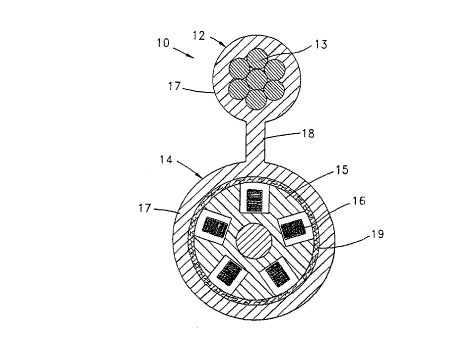
Referring to Figures 1-2, an exemplary self-supporting cable
that can be made by the apparatus and method of the present
invention will be described. Self-supporting cable 10 includes a
5 messenger section 12 having steel wirE:s 13, and a cable core
section 14 having a cable core 15 of t:he slotted rod type having
optical fiber ribbons 16 and a water absorbent tape 19 wrapped
s
around cable core 15. An extruded jacket 17 envelopes messenger
and cable core sections 12,14, and a web 18 of the jacket
1o connects the messenger and cable core sections together. Cable
core section 14 has an excess length c~f about 0.2~ relative to
messenger section 12 whereby cable core section 14 has at least
one undulation between webs 18 (Figure 2).
The present invention is directed t:o a method and apparatus
for making a self-supporting cable, for example, self-supporting
cable 10. The method and apparatus of the present invention can
be embodied in an exemplary manufacturing line 20 (Figure 3).
Manufacturing line 20 can include a core pay-off 21, a dancer 22,
a turning sheave 23, a length counter 24, a turning sheave 25, a
2o messenger wire pay-off 26, an extruder 27, a cooling trough 28, a
cable dryer 29, a length counter 31, a diameter gage 35, and a
cable take-up 36. In accordance with an~aspect of the present
invention, manufacturing line 20 includes a cable core tensioning
apparatus 30, a messenger wire tensioning apparatus 40, and a
cable tensioning apparatus 60.
Cable tensioning apparatus 60 preferably includes two
messenger tensioners 61,71 (Figure 4) in the form of multi-wrap
capstans (Figure 5) driven by motors (not shown). To provide
clearance for cable 10 to pass to tal~:e-up 36, the plane of
3o rotation of messenger tensioner 71 is angularly offset from that
of messenger tensioner 61 to the extE:nt of about one cable width,
and the center of rotation of messenger tensioner 71 is offset
from the center of messenger tensione~r 61 (Figure 5). Messenger
tensioner 61 preferably includes a sE:ries of receiving stations
63 for receiving self-supporting cab:Le 10 therein (Figure 6).
Cable tensioning apparatus 60 may inc=lude a guide sheave 72
7
A1026
CA 02275562 1999-06-18
removably mounted adjacent messenger i~ensioner 71 (Figure 5).
Each receiving station 63 includes a profile having a tensioning
recess 62, a clearance recess 64, and a medial portion 68 (Figure
7). Tensioning recess 62 may be in tile form of a radiussed
surf-ace, or a V-shaped groove, sized to grip jacket 17 around
messenger section 12. Clearance recess 64 preferably has an
arcuate shape, for example, an ellipsoid shape.
Manufacturing line 20 performs a method of making a self
supporting cable 10 comprising the steps of: drawing messenger
1o wire 13 and core 15 through cable manufacturing line 20;
extruding jacket 17 about messenger wire 13 and core 15 thereby
defining a cable 10; passing cable 10 across a tensioning
apparatus 60 having clearance section 64 receiving core section
14 of the cable; relieving tension in the cable as the cable
progresses through tensioning apparatus 60: and forming
undulations in core section 14 as the cable progresses through
tensioning apparatus 60 by maintaining a decoupled relationship
between core section 14 and clearance section 64 of tensioning
apparatus 60. -
2o More particularly, cable core 15 is fed from pay-off 21 to a
conventional dancer 22, around turning sheave 23, into length
counter 24, into cable core tensioning apparatus 30, and to
turning sheave 25. Cable core tensioning apparatus 30 is
preferably a single wrap tensioning capstan. Messenger wires 13
are fed from messenger wire payoff 26 to messenger wire
tensioning apparatus 40 and turning sheave 25 where messenger
wire 13 is turned toward extruder 27. Messenger wire tensioning
apparatus 40 is preferably a multi-wrap tensioning capstan that
is run at about a 0.2~ slower speed than core tensioning
3o apparatus 30 for assuring sufficient elongation to core section
14. At this point, messenger wire 13 and cable core 15 are fed
into extruder 27 wherein, for example, a polyethylene material
defining jacket 17 is extruded onto messenger wire 13 and cable
core 15 and a conventional plunger (not shown) is used to form
windows between webs 18. Next, jacket 17 is cooled in cooling
trough 28 and the outer diameter of jacket 17 is measured in
8
A1026
CA 02275562 1999-06-18
diameter gauge 35. The maintenance off: tension in messenger
section 12, as more fully described below, results in essentially
no undulation of core 15 in cooling though 28. The cable passes
into cable tensioning apparatus 60 an<i is wrapped about messenger
tens-Toners 61.71. Self-supporting cable 10 is then collected by
take-up reel 36.
Tensioning apparatus 60 pulls messenger wire 13 and cable core
through the extrusion process by maintaining a high degree of
tension on messenger wire 13. According to the present
io invention, there is essentially no relative difference in
velocity between messenger wire 13 and cable core 15 in the
crosshead of extruder 27. As appratus 40 is driven at a slower
speed relative to appratus 60, tension is cretaed in messenger
wire 13 between tensioning appratus 60 and messenger wire
15 tensioning appratus 40. As is best shown in Figure 7, tensioning
recess 62 grips messenger section 12, but clearance section 64 is
sufficiently decoupled from core section 14 whereby tensioning
apparatus 60 does not directly apply tension to core section 14.
Tensioning apparatus 60, in cooperation with messenger wire
2o tensioning apparatus 40, preferably creates tension directly in
messenger section 12 only. Some of the tension created in
messenger section 12, i.e., about 8,000-14,000 N, then flows
across webs 18 to core section 14, whereby core section 14 is
tensioned to a substantially less decfree compared to the tension
in messenger section 12, i.e., the tE:nsion in core section 14 is
about 100-300 N. To avoid tearing oi: webs 18, shear forces
acting on webs 18 and core section 1~6 are kept to the minimum
necessary to draw core section 14 through manufacturing line 20.
Additionally, the present invention may be practiced in the
3o form of a tensioning apparatus 80 including messenger tensioners
81 comprising elastomeric or plastic endless conveyors (Figure
9). Each endless conveyor includes a tensioning recess 82 and a
clearance recess 84. The endless conveyors can be mounted to a
conventional caterpuller type apparatus whereby the conveyors are
driven for rectilinearly applying tension to messenger 12.
9
A1026
CA 02275562 1999-06-18
Clearance recesses 84 permit the formation of undulations in
cable section 14.
The present invention embodies several advantages. For
example, clearance recesses 64,84 advantageously avoid direct
app~ieation of tension to core section 14, and facilitate the
ease of tension on core section 14 a:c cable 10 progresses through
tensioning apparatuses 60,80. Moreover, clearance recesses 64,84,
allow for a range of core section di~~meters. Additionally,
clearance recesses 64,84 permit the a:ssentially frictionless
1o formation of undulations in core 15, thereby avoiding damage to
webs 18 and undue deformation of the cable. The undulations may
be formed in any radial direction re7_ative to the center of core
section 14. The formation of undulat=ions occurs as cable 10
progresses from the entrance point oi'_ cable 10 in tensioning
apparatus 60, i.e., where tension is highest in messenger section
12, toward the exit of tensioning apparatus 60, at which point
tension in cable 10 is substantially dissipated. The release in
tension across tensioning apparatuses 60,80 advantageously
results in an overlength of core sect=ion 14 relative to messenger
2o section 12, for example, to a value of about 0.2~. There may,
however, be some incidental contact between core section 14 and
clearance section 64,84 which does not cause substantial friction
in core section 14. To reduce the ei'_fects of friction caused by
such incidental contact, for example" clearance recess 64 may
include one or more essentially frici~ionless journalled support
spacers 74 (Figure 10).
The present invention may be practiced in the form of a
tensioning apparatus 60' having at le=ast one knife 90 for forming
'windows between webs 18 (Figures il-:L4). A series of knives can
3o be formed adjacent medial portions 6!3' on a single wrap of a .
capstan 61' (Figure 14). Knives 90 preferably include sharpened
edges 92 for cutting the windows (Fi<~ures 11 and 13). Tensioning
apparatus 60' may include a pressing wheel 98 aligned with knives
90 so that the portion of jacket 17 ~~hat is to be removed will be
sandwiched between pressing wheel 98 and knife 90 whereby windows
will be formed in cable 10.
A1026
CA 02275562 1999-06-18
The present invention has been described with reference to
the foregoing embodiments, which embodiments are intended to be
illustrative of the present inventive concepts rather than
limiting. Persons of ordinary skill in the art will appreciate
that' variations and modifications of i~he foregoing embodiments
may be made without departing from this scope of the appended ,
claims. For example, clearance recesses according to the present3
invention may be any shape which resu:Lts in sufficient space for
the formation of undulations without undue friction in the cable
1o as the tension is released. The apparatus and method of the
present invention may be used in the making of self-supporting
fiber optic cables of the "figure 8" type characterized into the
two general categories mentioned hereinabove, i.e., self-
supporting cables with a core section having no excess length
relative to the messenger wire, and self-supporting cables having
a core section having an overlength, typically about 0.2~,
relative to the messenger wire.
11
A1026