Note: Descriptions are shown in the official language in which they were submitted.
CA 02275688 1999-06-18
WO 98/26738 PCT/ITS97/22140
-1-
DEVICE FOR THE TREATMENT OF INFARCTED TISSUE
AND METHOD OF USING THE DEVICE
FIELD OF THE INVENTION
The present invention is related generally to the modification of heart tissue
for
the treatment of myocardial infarction.
BACKGROUND OF THE INVENTION
As is well known, the heart has four chambers for receiving and pumping
blood to various parts of the body. During normal operation of the heart,
oxygen-
poor blood returning from the body enters the right atrium. The right atrium
fills
with blood and eventually contracts to expel the blood through the tricuspid
valve to
the right ventricle. Contraction of the right ventricle ejects the blood in a
pulse-like
manner into the pulmonary artery and each lung. The oxygenated blood leaves
the
lungs through the pulmonary veins and fills the left atrium. The left atrium
fills with
blood and eventually contracts to expel the blood through the mitral valve to
the left
ventricle. Contraction of the left ventricle forces blood through the aorta to
eventually deliver the oxygenated blood to the rest of the body.
Myocardial infarction (i.e., heart attack) can result in congestive heart
failure.
Congestive heart failure is a condition wherein the heart can not pump enough
blood.
When patients have a heart attack, part of the circulation to the heart wall
muscle is
lost usually do to a blood clot which dislodges from a larger artery and
obstructs a
coronary artery. If the clot is not dissolved within about 3 to 4 hours, the
muscle
which lost its blood supply necroses and subsequently becomes a scar. The
scarred
muscle is not contractile, therefore it does not contribute, to the pumping
ability of
the heart. In addition, the scarred muscle is elastic (i.e., floppy) which
further
reduces the efficiency of the heart because a portion of the force created by
the
remaining healthy muscle bulges out the scarred tissue (i.e., ventricular
aneurysm)
instead of pumping the blood out of the heart.
CA 02275688 1999-06-18
WO 98/26738 PCT/US97/22140
-2-
Congestive heart failure is generally treated with lots of rest, a low-salt
diet,
and medications such as A. C. E. inhibitors, digitalis, vasodilators and
diuretics. In
some myocardial infarction instances, the scarred muscle is cut out of the
heart and
the remaining portions of the heart are sutured (i.e. , aneurysmectomy). In
limited
circumstances a heart transplant may be performed.
Collagen-containing tissue is ubiquitous in the human body and makes up a
substantial portion of the scar. Collagen demonstrates several unique
characteristics
not found in other tissues. Intermolecular cross links provide collagen-
containing
tissue with unique physical properties of high tensile strength and
substantial
elasticity. A property of collagen is shrinkage of collagen fibers when
elevated in
temperature. This molecular response to temperature elevation is believed to
be the
result of rupture of the collagen stabilizing cross links and immediate
contraction of
the collagen fibers to about one-third of their original linear dimension or
the result of
a change in the hydration of the tissue . Another property of collagen is that
the
caliber of the individual fibers increases greatly, over four fold, without
changing the
structural integrity of the connective tissue.
There has been discussion in the existing literature regarding alteration of
collagen-containing tissue in different parts of the body. One known technique
for
effective use of this knowledge of the properties of collagen is through the
use of
infrared laser energy to effect tissue heating . The use of infrared laser
energy as a
corneal collagen shrinking tool of the eye has been described and relates to
laser
keratoplasty, as set forth in U.S. Patent No. 4,976,709. The importance of
controlling the localization, timing and intensity of laser energy delivery is
recognized
as paramount in providing the desired soft tissue shrinkage effects without
creating
excessive damage to the surrounding non-target tissues. Another known
technique of
altering collagen is described in U.S. Patent No. 5,458,596 to treat joints.
U.S.
Patent No. 5,437,664 describes using a catheter for venous occlusion and
coagulation
of blood.
Thermal destruction (i.e. , ablation) of problematic myocardial tissue (i.e. ,
arrhythmogenic focus) is a therapeutic procedure used with increasing
frequency for
the treatment of cardiac arrhythmias (e. g. , ventricular tachycardia) as
described in
CA 02275688 1999-06-18
WO 98/26738 PC'T/US97/22140
-3-
U.S. Patent No. 5,246,438. The treatment of cardiac arrhythmias involves
treating
electrically problematic but otherwise healthy tissue. As a result one goal of
ablation
is to localize the heat as much as possible so as to restrict the ablation to
only the
problematic healthy tissue.
SUMMARY OF THE INVENTION
The present invention provides a device and method for treating infarct scar
tissue of a mammalian heart by selectively heating the infarct scar to reduce
the size
of the scar tissue surface area, increase the cross-section of the scar
tissue, stiffen the
floppy portion of the scar tissue, reduce the ventricular systolic wall
tension, and
increase the overall pumping efficiency of the infarcted heart by eliminating
the
ventricular aneurysm, if present. The present invention preferably does not
affect the
healthy heart tissue or ablate the infarcted tissue. Furthermore, preferably
the present
invention diffuses the heat over the infarcted area.
The method is similar to an annealing process wherein the scar tissue
undergoes heating and then is allowed to cool slowly. The heat can be applied
to or
induced in the infarct scar. Force can also be applied in accordance with the
present
invention to assist the reduction of the size of the scar. Generally speaking,
besides
reducing the surface area of the scarred tissue, the present invention alters
the
material properties of the infarct scar such as making it stiffer and less
elastic.
In one aspect of the invention, there is provided an apparatus for heating an
infarct scar in a heart having a heating element having a projection for
piercing the
scar and a mechanism for squeezing at least two portions of the scar toward
each
other.
In another aspect of the invention, there is provided a method for treating an
infarct scar in a heart including the step of energizing a heating element to
raise the
temperature of the infarct scar to a temperature sufficient to reduce the
surface area of
the infarct scar.
In yet another aspect of the invention, there is provided a method for
training a
person to perform a method for treating an infarct scar in a heart including
the steps
of demonstrating or instructing how to do the following step of energizing a
heating
CA 02275688 1999-06-18
WO 98/26738 PCT/US97/22140
-4-
element to raise the temperature of the infarct scar to a temperature
sufficient to
reduce the surface area of the infarct scar.
In still another aspect of the invention, there is provided a modified
mammalian heart having a contracted infarct scar tissue portion diminished in
its
surface area and stiffened.
In yet another aspect of the invention, there is provided a method for
treating
an infarct scar in a heart including the step of energizing a heating element
to raise
the temperature of the infarct scar to a temperature sufficient to reduce the
ventricular
systolic wall tension.
BRIEF DESCRIPTION OF THE DRAWINGS
As used herein, like reference numerals will designate similar elements in the
various embodiments of the present invention wherein:
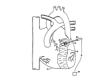
FIG. 1 is a mammalian heart with electrodes inserted in an infarcted area;
FIG. 2 is a mammalian heart with a radio-frequency heating element in contact
with the infarcted area;
FIG. 3 is a front view of a device for heating and squeezing portions of the
infarcted area together;
FIG. 4 is a side view of the device of FIG. 3; and
FIG. 5 is a top view of the device of FIG. 2 during treatment of the infarcted
area.
DETAILED DESCRIPTION OF THE PREFERRED EMBODIMENTS
The present invention provides a device and method for altering the material
properties of collagen-containing infarcted tissue in a patient's heart. There
also is
provided a method of training a person to perform a method for treating an
infarct
scar in a mammalian heart. The invention is used to accurately control the
inducement of heat or application of heat within a specific thermal range, and
deliver
thermal energy to the collagen-containing infareted tissue to reduce the size
of the scar
tissue area by shrinking the infarcted tissue in the heart and stiffening the
floppy
portion of the scar tissue without ablating the tissue. As a result, the
overall pumping
CA 02275688 1999-06-18
WO 98/26738 PCT/LTS97/22140
-5-
efficiency of the infarcted heart is increased. Likewise, a modified mammalian
heart
having a contracted infarct scar tissue portion diminished in its surface area
and
reduced ventricular systolic wall tension results.
' Referring initially to FIG. 1, there is illustrated a heart 10 having an
infarcted
region or portion 12. The infarcted portion 12 of the heart can be accessed
with
conventional open chest surgery or with arthroscopic techniques. A positive
electrode
14 and negative electrode 16 are inserted in a portion of the infarcted
portion 12 to
induce resistive heating in the infarct scar in the desired treatment area 18
when
energy is applied across the electrodes. Alternatively, the positive and
negative
electrodes can be placed in contact with the infarcted scar. The positive and
negative
electrodes function as a heating element as they are energized to raise the
temperature
of the scar in the desired treatment area 18 to a temperature sufficient to
reduce the
surface area of the scar without ablating the scar tissue or damaging the
healthy tissue
surrounding the infarcted portion 12. The term "heating element" as used
herein
encompasses elements that apply energy thereby inducing heat in the tissue as
well as
to elements that apply heat to the tissue. In a preferred embodiment, the scar
is
heated to a temperature in the range of about 40 degrees Celsius to about 75
degrees
Celsius, more preferably about 60 degrees Celsius to about 65 degrees Celsius.
After
the desired treatment area 18 has been heated, it is allowed to cool. Energy
is no
longer applied after there has been sufficient shrinkage of the scar tissue.
Sufficient
shrinkage may be detected visually, mechanically, echocardiograhically,
ventriculographically with x-ray, fluoroscopically or with appropriate feed
back
variables, such as impedance monitoring, temperature monitoring, or any other
suitable method. The electrodes or heating element can then be moved to
another
portion of the infarcted portion 12 for treatment. It is believed, without
being limited
to a particular theory, that as the infarct scar is heated the collagen fibers
straighten
then as the collagen fibers cool they re-entwine or refold around each other
becoming
shorter, tighter, thicker, stronger, stiffer, or some combination of these
qualities.
The method is contemplated to be used with any suitable appliance for
applying radiant energy, thermal energy, or to otherwise heat the infarcted
tissue and
reduce the area of the infarcted tissue. For example, a radio-frequency
generator 20
CA 02275688 1999-06-18
WO 98/26738 PCT/US97/22140
-6-
and heating element applicator 22 can be used (FIG. 2). When the heating
element 24
of the applicator 22 is positioned at the desired treatment site, the radio-
frequency
generator 20 is activated to provide suitable energy, preferably at a selected
frequency
in the range of 10 megahertz to 1000 megahertz, to heat the scar tissue to a
temperature sufficient to reduce the surface area of the scar without ablating
the scar
tissue or damaging the healthy tissue surrounding the infarcted area 12.
Preferably,
the emitted energy is converted within the scar tissue into heat in the range
of about
40 degrees Celsius to about 75 degrees Celsius, more preferably in the range
of about
60 degrees Celsius to about 65 degrees Celsius. The radio-frequency energy is
preferably applied at low power levels (e.g., 1 to 20 watts). Suitable radio-
frequency
power sources are readily commercially available. In one embodiment, the radio-
frequency generator 20 has a single channel, delivering approximately 1 to 20
watts of
energy and possessing continuous delivery capability.
The heating element 24 of the applicator 22, as shown in FIG. 2, operates as a
unipolar electrode. An outer electrode (not shown) having a much larger
surface area
than the heating element 24 is placed on the outer surface of the patient's
body. For
example, an external metal mesh or solid plate is placed on the skin. Both
electrodes
are connected to radio-frequency generator 20 which produces an electric field
at a
high frequency within the patient's body. Because the surface area of the
heating
element 24 is much smaller than that of the outer electrode, the density of
the high
frequency electric field is much higher around the heating element. The
electric field
reaches its highest density between the two electrodes in the region near the
heating
element 24. The increased density of the field around the heating element 24
produces localized heating of the scar tissue in the treatment area 18.
Alternatively,
two electrodes can be placed on the scar and energized in a bipolar fashion.
Referring to FIGS. 3-S, another embodiment for a heating device is shown.
The heating device of FIGS. 3-5 is comprised of a scissor-like clamp 26 having
crossing arms 28 and 30 which are connected by pin 32 near the mid-point of
the
arms. At the proximal end of arms 28 and 30 are handles 34 and 36,
respectively,
and at their distal ends 38 and 40, respectively, a plurality of protrusions
42 spaced
along elongated members 44 and 46, respectively . An optional releasable lock
48 is
CA 02275688 1999-06-18
WO 98/26738 PCT/US97/22140
located between arms 28 and 30. Likewise, an optional fixed force spring can
be
located between the arms. Attached to arm 28 is a positive electrode 50 and
attached
to arm 30 is negative electrode 52. Each of the arms 28 and 30 are free to
rotate
about pin 32 and are electrically isolated from each other such that when a
potential is
applied between the electrodes 50 and 52 there is no short between the arms.
The clamp 26 is used by a surgeon (or an individual demonstrating) to squeeze
and shrink a portion of the area of the infarct scar tissue 12. (Likewise, an
individual
can instruct a surgeon on how to accomplish the method of the present
invention with
the clamp 26 or other embodiments disclosed herein. ) The surgeon grabs (or
pierces
the scar tissue with the protrusions 42, if present) and squeezes the two
portions of
the scar tissue toward each other by actuating the clamp with the handles 34
and 36
(FIG. 5). The protrusions 42 when present are conductive elements. The
positive
and negative electrodes are then energized by the surgeon to function as a
heating
element to raise the temperature of the scar in the desired treatment area 18
to a
temperature sufficient to reduce the surface area of the scar without ablating
the scar
tissue or damaging the healthy tissue surrounding the infarcted portion I2.
The
protrusions can be used to treat endocardial, sub-endocardial and transmural
infarcted
areas. The protrusions can have insulated proximal portions such that the
distal
portions are used to treat endocardial infarcted areas. Alternatively, the
protrusions
can have insulated distal portions such that the proximal portions are used to
treat sub-
endocardial infarcted areas. The protrusions can be uninsulated to treat
transmural
infarcted areas. Likewise, only a portion of a side of a protrusion may be
insulated.
The clamp 26 is beneficial in applying force to the infarcted tissue to assist
in
the shrinking process. The releasable lock 48 or fixed force spring can be
used to
preset the distance which the two portions of the scar are going to be moved
toward
each other. Alternatively, the releasable lock can be used to hold the two
portions
steady at a given distance during the heating process. The elongated members
44 and
. 46 are generally not brought close together so that a larger area of the
scar can be
treated. Generally, the elongated members 44 and 46 are actuated toward each
other
so as to apply a relatively small amount of force to assist the shrinking
process. The
clamp 26 illustrated in FIGS. 3-5 utilizes resistive heating of the scar
tissue, but it is
CA 02275688 1999-06-18
WO 98/26738 PCT/US97I22140
_g_
also within the scope of the invention that a radio-frequency generator and
electrodes,
as well as other means to be described below, can be utilized.
The heating element of any of the embodiments can be made to provide
protection against overheating of the scar tissue. Techniques, for example
S temperature monitoring or electrical characteristic monitoring (e.g.,
impedance), can
be utilized in a system which shuts down the application of energy to the
heating
element to avoid ablating the tissue or damaging healthy tissue. The surgeon
can, if
desired, override the feedback control system. A microprocessor can be
included and
incorporated into the feedback control system to switch the power on and off,
as well
as modulate the power. The microprocessor can serve as a controller to watch
the
temperature and modulate the power in order to avoid over-heating of the
tissue. The
heating element can be synchronized with the ECG so that the heart wall is in
diastole. Furthermore, the system can include auditory or visual feedback
indicators
for signalling when shrinkage, temperature, or other variables are occurring
and also
when any have reached or exceeded desired conditions.
It is to be understood that other forms of energy, in addition to those
discussed
above, such as microwaves, ultrasound, and light (either coherent or
incoherent
sources) can be used, and that the thermal energy generated from a hot fluid
element
(e.g., liquids, gases, combinations of liquids and gases, etc.), a curie point
element,
or similar elements can be used as well. Heating element 42 in accordance with
any
of the embodiments can be a number of different materials including but not
limited to
conductive polymer, stainless steel, platinum, or other noble metals.
While several particular embodiments of the invention have been illustrated
and described, it will be apparent that various modifications can be made
without
departing from the spirit and scope of the invention. Accordingly, it is not
intended
that the invention be limited, except as by the appended claims.