Note: Descriptions are shown in the official language in which they were submitted.
CA 02275823 1999-06-15
1
Method for Measuring Interference Effects on
Glass Fiber Transmission Links as well as a Transmission System
The invention is based on a method for measuring interference effects of a
glass fiber
transmission link as well as a transmission system according to the generic
class of the
independent claims. In Proceedings II, NOC '97, Antwerp, H. Bulow, pp. 65-72,
the effects of
polarization mode dispersion are described. Polarization mode dispersion
occurs due to the
birefringent effects in the glass fibers used for the transmission links. The
light signal is divided
into two components corresponding to the fast and the slow axes of the
polarization states,
whereby these two components are transmitted at different group velocities
over the glass fiber
link. The different group velocities of the two signal components cause
interference and, in the
general case, disturbance of the data information. The polarization mode
dispersion effect is a
statistical effect since the behavior of glass fibers varies due to their
temperature, their state of
CA 02275823 1999-06-15
2
strain, as well as due to aging effects. The change of the polarization mode
dispersion is generally
a slow process that takes place over longer periods. Consequently, it is not
necessary to
continuously measure the effects of polarization mode dispersion for a
transmission link.
US 5 473 457 discloses a method for measuring polarization mode dispersion.
According to this
method, the light signal is transmitted via a fiber and the polarization state
is subsequently
measured in a polarization controller. The signal is then supplied to a
polarization maintaining
fiber. The two polarization planes of the light are then separated in a device
and coherently
superimposed. The signal serves to calibrate the polarization controller. In
this manner, the
polarization state of the signal is actively influenced. .
The inventive method for measuring interference effects caused by polarization
mode dispersion
with the characteristic features of the independent claim has the advantage,
in contrast, that a
simple measurement of an output signal comprising two frequency bands at a
coherent receiver
supplies a measure for the effects, which is available for further analysis.
This method completely
dispenses with the use of polarization controllers, as well a polarization
measurements, and
polarization maintaining fibers, all of which are optical components that
cause great complexity
and great costs. The method according to the invention makes possible a simple
measurement of
the characteristics of the transmission link by purely electric means.
The procedures set forth in the subclaims permit advantageous further
embodiments and
improvements of the method defined in the independent claim. Using this
measuring method and
using a high frequency, e.g. of 60 GHz, can determine PMD at the receiver by
means of a
CA 02275823 1999-06-15
3
coherent measurement method. Advantageously, the method according to the
invention is not
used for the entire transmission period since polarization mode dispersion
involves slow changes
of the properties of the transmission link. It is therefore advantageous to
use only one modulator,
which as a measuring unit produces a side band modulated signal at least from
time to time and
thus delivers a signal that can be evaluated for the measurement.
A further advantage of the method is that it can be used online and thus
permits a continuous
transmission of the side band modulated signals for statistical recording and
analysis.
The transmission system according to the invention, comprising an optical
sender, a transmission
link, and an optical receiver, has the advantage that one modulator produces
the side bands for
the measuring signal, while a second modulator processes the signals for the
data. A further
advantageous embodiment uses one modulator for both producing the side bands
and for data
modulation.
An exemplary embodiment of the invention is depicted in the drawing and
explained in further
detail in the following description.
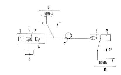
Figure 1 shows a transmission system according to the invention. An optical
sender (1 ) is
connected with a transmission link (7). In the optical sender (1 ) there is a
laser (2) whose output is
connected with the input of a modulator (3). The modulator (3) has an
additional input, which is
connected with an external oscillator (5). The output of the modulator (3) on
the input side is
coupled to an optical amplifier whose output is connected with the
transmission link (7). At the end
of the transmission link (7) is a photodiode (8), possibly with electric
amplifier, the output of which
is connected to a PC (9). The optical source (1 ) is a laser (2), which
produces two optical carriers
CA 02275823 1999-06-15
4
with a frequency spacing of 60 GHz by means of double side band modulation,
see View 6. By
coherent detection, an electrical carrier is produced at 60 GHz on the
photodiode (8) on the
receiver side, see View 10. The power of this carrier at 60 GHz is a function
of the polarization
state of the two optical carriers or, more precisely, of the scalar product of
the two fields. The
polarization mode dispersion causes the polarization state of the fields in
the two optical carriers
to change. Thus, the electrical power detected in the receiver (9) also
changes. Consequently, the
detected power at the carrier frequency of 60 GHz is a measure for the change
of the polarization
mode dispersion on the transmission link. This simple measurement permits the
detection of the
momentary polarization mode dispersion of the transmission link as well as the
analysis of the
statistical behavior of the glass fiber link. The measured power is evaluated
by a PC (9) and
processed. This measurement method permits the time recording of changes in
the polarization
mode dispersion up to change frequencies greater MHz [sic]. The knowledge of
the value of the
polarization mode dispersion can be actively used for a compensating circuit
in the receiver.
Prerequisite for a measurement is the use of two bands separated by a
frequency f. These do not
need not be equally polarized or have equal power. This is why two lasers can
be used as optical
sources. How the two bands are produced is not important. Only the frequency
spacing between
the bands is significant since the resolution of the PMD effect is better at
high frequencies.