Note: Descriptions are shown in the official language in which they were submitted.
CA 02276181 1999-06-22
_1_
PATENT
571 1 1-5064
DEVICE FOR STORING ELONGATED OBJECTS
Field of the Invention
The present invention relates to a device for storing objects, and more
particularly to a device having spaced mounting bars for storing elongated
objects.
Background of the Invention
When not in use, elongated rods such as those used for hanging clothing and
the like are often difficult to store. For example, moving companies sell
wardrobe
boxes that are designed to transport clothing. The box comes with an elongated
crossbar that spans across the box interior allowing hangered clothing to be
hung just
the same as in a closet. When not in use these crossbars must be stored in a
place
where they can be seen by a consumer, but do not take up a great deal of room.
Due
to their awkward size and length, when these crossbars are placed on the floor
they
tend to take up a large amount of floor space. When leaned against a wall or
in a
corner they often slide and/or fall over. Floor racks have been designed for
containing
rods or the like. However, the rack itself typically requires a large amount
of floor
space in the retailers showroom.
A need exists for a rack that holds elongated rods, crossbars and the like
above
a floor, yet does not take up a large amount of floor space.
Summary of the Preferred Embodiments
In accordance with one aspect of the present invention, there is provided a
device for storing objects that includes a mounting member and a rack assembly
affixed to the mounting member. The rack assembly includes first and second
Express Mail #EM099217062US
LADOCS\2417918 2
CA 02276181 1999-06-22
-2-
mounting bars in spaced relation and at least one connection member holding
the first
and second mounting bars in spaced relation.
In a preferred embodiment, the fir:ct and second mounting bars define a
mounting plane and the connection members) include first and second ends and a
middle portion. The first and second ends of the connection members) are
affixed
to the first and second mounting bars, respectively, and the middle portion
extends
above the mounting plane.
In another preferred embodiment, the first and second mounting bars are in
parallel spaced relation.
In accordance with another aspect of the present invention, there is provided
a device for storing objects that includes an elongated mounting member, and a
rack
assembly affixed to said mounting member. The rack assembly includes first and
second mounting bars and at least one intermediate connection member. The
first
and second mounting bars each have a middle portion and ends that extend
upwardly
and are spaced apart. The middle portion of the first and second mounting rods
define a mounting plane. The at least one intermediate connection member has a
first
end that extends inwardly from the middle portion and is affixed to the first
mounting
bar and a second end that extends inwardly from the middle portion and is
affixed to
the second mounting bar and a middle portion that extends above the mounting
plane. The elongated mounting member is affixed to the middle portion of the
at
least one intermediate connection member.
In accordance with yet another aspect of the present invention, there is
provided a rack assembly for storing objects that includes a mounting member,
a
mounting bar in spaced relation with the; mounting member and at least one
connection member holding the mounting bar and the mounting member in spaced
relation.
In accordance with another aspect of the present invention, there is provided
a method of storing an elongated object having an elongated portion and a
mounting
portion on a device that includes a mounting member and a rack assembly
affixed to
the mounting member. The rack assembly includes first and second mounting bars
Express Mail #EM099217062US
IJ~DOCS\2417948 2
CA 02276181 1999-06-22
in spaced relation and at least one connection member holding the first and
second
mounting bars in spaced relation. The method includes the steps of mounting
the
mounting member on a structure and disposing the elongated object between the
first
and second mounting bars. When mounted, the elongated portion is between the
first and second mounting bars and the mounting portion is engaged with the
first
and second mounting bars.
Other objects, features and advantages of the present invention will become
apparent to those skilled in the art from the following detailed description.
It is to be
understood, however, that the detailed description and specific examples,
while
indicating preferred embodiments of the present invention, are given by way of
illustration and not limitation. Many changes and modifications within the
scope of
the present invention may be made without departing from the spirit thereof,
and the
invention includes all such modifications.
Brief Description ~~f the Drawings
The invention may be more readily unclerstood by referring to the accompanying
drawings in which
Figure 1 is a perspective view of a device for storing elongated objects in
accordance with a first preferred embodiment of the present invention, showing
a
stored object in phantom.
Figure 2 is an end elevation of this device of Figure 1 showing the rack
assembly affixed to the mounting member and a stored object in phantom.
Figure 3 is a top plan view of the device of Figure 1 showing a stored object
in
phantom.
Figure 4 is a perspective view of a device in accordance with a second
embodiment of the present invention, showing the mounting member spaced from
and attached to the mounting bar with a svcored object in phantom.
Figure 5 is a side elevation showing an angled connection member in
accordance with an alternative embodiment of the present invention.
Express Mail #EM099217062US
IaDOCS\2417948 2
CA 02276181 1999-06-22
Figure 6 is a perspective view showing the connection members lying in the
same plane as the mounting bars in accordance with an alternative embodiment
of
the present invention.
Figure 7 is a perspective view showing a device for storing elongated objects
with a plurality of intermediate connection members in accordance with a third
preferred embodiment of the present invention.
Figure 8 is an end elevation of the device of Figure 7 showing the rack
assembly affixed to the mounting member and a stored object in phantom.
Like numerals refer to like parts throughout the several views of the
drawings.
Detailed Description of then Preferred Embodiments
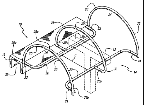
Referring to Figures 1-3, a first embodiment of a device 10 for storing
elongated
objects 12 includes a rack assembly 14 affixed to a mounting member 16. It
will
be appreciated that terms such as "upwardly," "outwardly," "inwardly,"
"above,"
"below" and "horizontal" used hereinbelo~w are merely for ease of description
and
refer to the orientation of the components as shown in the Figures. It should
be
understood that any orientation of device 10 described herein is within the
scope of
the present invention.
Preferably, the rack assembly 14 includes first and second elongated mounting
bars 18 and 20 in substantially parallel spaced relation. The first and second
elongated mounting bars 18 and 20 preferably each include ends 22 and 24,
respectively, that extend outwardly away from the opposing mounting bar, as
shown
in Figure 1. In the first embodiment, the ends 22 and 24 preferably extend at
approximately a 90° angle. However, it will be understood that the ends
22 and 24
can extend at any desired angle, or can be curved.
Preferably, the first and second mounting bars 18 and 20 define a
substantially
horizontal mounting plane. Also, preferably, the ends 22 and 24 of the first
and
second mounting bars 18 and 20, lie in the substantially horizontal mounting
plane.
Alternatively, ends 22 and 24 of the mounting bars 18 and 20 can extend above
or
below the substantially horizontal mounting plane.
Express Mail #EM099217062US
LADOCS\2117948 2
CA 02276181 1999-06-22
-5-
A plurality of connection members :26 hold the mounting bars 18 and 20 in
spaced relation. The connection members 26 have first and second ends 26a and
26b, and a middle portion 26. The rack assembly 14 includes two end connection
members 28 and at least one intermediate connection member 30. The end
connection members 28 are preferably arcua~te in shape. The first end 26a of
an end
connection member 26 is affixed to one of the ends 22 of the first mounting
bar 18,
the second end 26b is affixed to one of the ends 24 of the second mounting bar
20,
and the middle portion 26c extends above the substantially horizontal mounting
plane, as shown in Figures 1-3.
The intermediate connection member 30 preferably has an arcuate middle
portion 26c and first and second ends 26a and 26b that extend inwardly from
the
middle portion 26c as shown in Figure 1 . Preferably, the first and second
ends 26a
and 26b of the intermediate connection mennber 30 lie in the substantially
horizontal
mounting plane, and the middle portion 26c extends above the substantially
horizontal mounting plan. However, the first and second ends 26a and 26b of
the
intermediate connection member need not lie in the substantially horizontal
mounting
plane. For example, they can extend inwardly at an angle. It will be
understood that
the rack assembly 14 can include any number of intermediate connection members
30.
As stated above, the portion of the connection members 26 that extends above
the substantially horizontal mounting plane is preferably arcuate. However,
the
connection members 26 can be other advantageous shape. For example, they may
comprise a plurality of straight portions including a plurality of angles,
that form a
unit, as shown in Figure 5, or they may include a combination of straight and
curved
portions.
As illustrated, the mounting bars 18 and 20 and the connection members 26
have circular cross-sections. However, if desired, the mounting bars 18 and 20
and
the connection members 26 can have square:, oval or other cross-sections. It
will be
appreciated by those skilled in the art that the connection members 26 are
dimensioned such that when an elongated object 12 is placed on the mounting
bars
Express Mail #EM099217062US
IaDOCS\2417948 2
CA 02276181 1999-06-22
-6-
18 and 20, as illustrated in Figure 1, the mounting portion 12b of the
elongated
object 12 does not come into contact with the connection members 26.
Mounting bars 18 and 20 are in substantially parallel spaced relation, thereby
defining a distance D therebetween. The distance D is predetermined so that
objects
12 to be stored in the device 10 fit therein, ~snd is in no way meant to be a
limitation
on the present invention. The distance D is of sufficient dimension to allow
the
elongated portion 12a to fit between the mounting bars 18 and 20, and the
mounting
portion 12b to extend across distance D and engage the mounting bars 18 and
20,
as best shown in Figure 2. In other words, the length L of the mounting
portion 12b
is preferably greater than distance D.
The mounting member 16 preferably defines a mounting channel 32 which is
adapted to engage an elongated member, such as a rack in a retailer's
showroom.
The rack assembly 14 can be connected to the mounting member in any number of
ways. Preferably, the ends 22 of the first mounting bar 18 are affixed to the
mounting member 16 as shown in Figure 1. However, the connection members 26
can also be affixed to the mounting member 16. It will be understood that
other
means for mounting the rack assembly 14 are within the scope of the present
invention. For example, clamps, hooks, fasteners, threaded fasteners,
adhesives,
magnets, chains, ropes and other conventional securing means can be used to
secure
the rack assembly 14 to a structure or the like.
Preferably, all of the components of the device 10 are comprised of a rigid
metal and are welded together. However, the entire device 10 or separate
components thereof can be comprised of other materials such as a rigid
plastic, wood
or the like. Also, the components can be affixed to one another by gluing or
with
threaded fasteners or other conventional attachment or connection methods.
Furthermore, the entire device 10 can be formed as one unit, for example, by
casting.
It will be understood that the material used and the method of affixing
components
to one another are not intended to be limitations on the present invention.
In operation, the mounting member '16 is mounted on a structure, such as a
rack or the like, and an elongated object 12 is placed into the rack assembly
14
Express Mail #EM099217062US
LADOCS\2417948 2
CA 02276181 1999-06-22
through the entry area 34 defined below an end connection member 28. The
elongated object 12 is placed onto the mounting bars 18 and 20 such that the
elongated portion 12a is between the mounting bars 18 and 20 and the mounting
portion 12b is in contact with the top surface of the mounting bars 18 and 20
as best
seen in Figure 2. It should be understood that the distance D is less than the
length
of the mounting portion 12b of the elongated object 12. The elongated object
12
can then be slid into a desirable position.
Referring to Figure 4, in a second preferred embodiment, the device 100
includes a rack assembly 102 with an integral mounting member 16. This
embodiment is similar to the first embodirnent described above with the
mounting
member 16 replacing the first mounting bar 18. Preferably, the mounting member
16 and the mounting bar 104 are in substantially parallel spaced relation, and
define
a substantially horizontal mounting plane. The mounting bar 104 has ends 104a
that
extend outwardly, as shown in Figure 4.
The rack assembly 102 includes at least one connection member 26 that
connects the mounting member 16 and the mounting bar 104 and holds them in
spaced relation. The connection members. 26 have first and second ends 26a and
26b, and a middle portion 26c, and are preferably arcuate in shape. Rack
assembly
102 preferably includes two end connection members 106 and at least one
intermediate connection member 30. The first end 26a of an end connection
member
106 preferably lies in the substantially horizontal mounting plane, extends
inwardly
from the middle portion 26c and is affixed to the mounting member 16. The
second
end 26b of an end connection member 106 is affixed to one of the opposite ends
104a of the mounting bar 104, and the middle portion 26c extends above the
substantially horizontal mounting plane, as shown in the Figure 4.
The intermediate connection member a0 preferably has a curved middle portion
26c and first and second ends 26a and 2fib that extend inwardly from the
middle
portion 26c as shown in Figure 4. Preferably, the first and second ends 26a
and 26b
of the intermediate connection member 30 lie in the substantially horizontal
mounting
plane, and the middle portion 26c extends above the substantially horizontal
Express Mail #EM099217062US
LADOCS\2~1794B 2
CA 02276181 1999-06-22
mounting plane. It will be understood that the rack assembly 102 can include
any
number of intermediate connection members 30.
In Figure 6, a device 200 for storing elongated objects 12 includes connection
members 26 that lie in substantially the same plane as the mounting bars 18
and 20.
In Figures 7-8, a third preferred embodiment of a device 300 for storing
elongated objects 12 is shown. Device 300 includes mounting bars 18 and 20
with
respective ends 322 and 324 that extend upwardly to prevent objects thereon
from
falling off. In this particular embodiment, mounting bars 18 and 20 each
include a
middle portion 18a and 20a that together define a horizontal mounting plane.
Ends
322 and 324 extend above the mountiing plane. A plurality of intermediate
connection members 30 are provided for holding mounting bars 18 and 20 in
spaced
relation. The mounting member 16 is affixed to the middle portion 26c of the
intermediate connection member 26. Ends ;322 and 324 preferably extend
upwardly
at approximately a 90° angle. However, it will be understood that ends
322 and 324
can extend at any desired angle, or can be curved.
The alternative embodiments of Figures 5 and 6 are shown as modifications to
the first embodiment described above. It will be understood that similar
modifications
can be made to the second and third embodiments as well.
Other alternative embodiments are also within the scope of the present
invention. For example, the mounting bars) can have stops affixed thereto for
preventing the elongated objects from falling out. The mounting bars (or
mounting
bar and mounting channel) can be in non-parallel spaced relation. The mounting
bars
or mounting member can be curved, thereby being in radially spaced relation,
or
angled rather than straight. The mounting member can be omitted. The rack
assembly can include only one connection rnember. The mounting member and the
mounting bar(s)can be different lengths. A,II such modifications are intended
to be
within the scope of the present invention as defined by the claims appended
hereto.
Express Mail #EM099217062US
LADOCS\2417948 2