Note: Descriptions are shown in the official language in which they were submitted.
CA 02276545 1999-06-29
Attorney Docket No. 6757-000004
SNAP/SNAPI,E55 COVER h'OR THE CARGO AREA OF A VESICLE
BACKGROUND OF THE lhIVENTION
1. Technical Field
The present invention generally relates to tonnesu covers for truck beds and,
more
particularly, to a tonneau cover rail assembly which universally accommodates
tonneau covers
having snap-type fastening mechanisms and tonneau covers having hook-type
fastening
mechanisms.
2. Discussion
Tonneau covers are used to cover openings within vehicles. Tonneau covers are
commonly
used to cover seating sections of boats and convertible cars, as well as pick-
up tzuck beds. Tonneau
covers are advantageous since they provide protection from the elements for
the contents thereunder
and improve aerodynamics.
For years, tonneau covers utilized snap-type fastening mechanisms for securing
the cover
to the vehicle. In this type of mechanism, several snap receptacles sre
secured directly to a vehicle.
The tonnesu cover is provided with mating snaps which are snapped onto the
snap receptacles.
While adequate, this type of fastening arrangement requires extensive tooling
to embed the snap
receptacles into the vehicle and, once the snap receptacles are in place, they
cannot be easily
removed.
Today, most tonneau cover assemblies include a rail network which is attached
to the top
ofthe vehicle bed sidewalk. U'.S. Patent Nos. 4,639,033 to Whcatley ct al. and
4,496,184 to Byrd
et al. show tonncau cover assemblies using a rail network. After the rail
network is secured to the
vehicle, the tonnesu cover is secured to the rails.
1
CA 02276545 1999-06-29
Rail networks commonly employ one of two types of fastening mechanisms for
interconnecting with a tonneau cover. The fast type includes a plurality of
snap receptacles which
cooperate with mating snaps coupled about the pezimeter of the cover, The
second type employs
an elongated slot for cooperating with an elongated hook coupled about the
perimeter, of the cover.
As such, a different rail network is required for use in conjunction with each
type of cover. That
is, a covet having a snap-type fastening mechanism requires a rail network
having mating snap
receptacles. Similarly, a cover having hook-type fastening mechanisms requires
a rail network
having mating channels. As such, a retailer must maintain an inventory of both
snap-type and hook-
type rail networks for use with each type of cover.
In view of the foregoing, it would be desirable to provide a rail network for
a tonneau cover
which universally accommodates both snap-type fastening mechanisms and hook-
type fastening
mechanisms.
SUMMARY OF THE INVENTION
The above and other obj octs are provided by a tonneau cover assembly
including a front tail,
a rear rail, and hvo side rails. Each of the rear and two side rails includes
a pair of opposed lips
defining a channel therein, The channel slidably receives a plurality of snap
receptacles for
cooperating with mating snaps of a tonneau cover having a snap-type fastening
mechanism. The
channel also receives a hook-type retention member and retains it therein so
that a tonneau cover
having a hook-type fastening mechanism can be secured thereto. Accordingly, a
single rail network
can be used with either a snap-type tonneau cover fastening mechanism or a
hook-type tonnesu
cover fastening mechanism.
2
CA 02276545 1999-06-29
BRIEF DESCRIPTION OF THE DRAWINGS
In order to appreciate the manner in which the advantages and objects of the
invention are
obtained, a more particular description of the invention will be rendered by
reference to specific
embodiments thereof which are illustrated in the appended drawings.
Understanding that these
drawings only depict preferred embodiments of the present invention and are
not therefore to be
considered limiting in scope, the invention will be described and explained
with additional
specificity and detail through the use of the accompanying drawings in which:
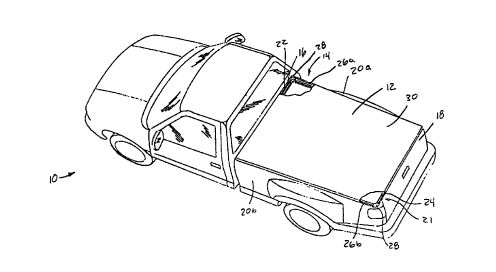
FIG. 1 is a perspective view of a truck including a tonneau cover assembly
coupled thereto
according to the present invention;
FIG. 2 is an e~tploded bottom view of the tonneau cover assembly of FIG. I
illustrating both
interchangeable cover members;
FIG. 3 is an exploded perspective view of a corner assembly of the tonneau
cover assembly
of FIGS. 1 and 2;
FIG. 4 is a cross-sectional view of the front rail of the tonncau cover
assembly of FIG. 2
taken along line 4-4;
FIG SA is a cross-sectional view of the side rail of the tonneau cover
assembly of FIG. 2
taken along Iine 5-5 with a cover secured thereto using a snap-type fastening
mechanism; and
FIG. SB is a cross-sectional view of the side rail of the tonneau cover
assembly of FIG. 2
taken along line 5-5 with a cover secured thereto using a hook~type fastening
mechanism.
DETAILED DESCRIPTION OF THE PREFERRED EMBODIMENTS
The present invention is directed towards a tonncau cover assembly for the
cargo area of a
truck. The tonneau cover assembly includes a plurality of rails adapted to
accommodate a cover
having either a plurality of snap members coupled thereto or a plurality of
hook members coupled
thereto. As such, the plurality of rails can be interchangeably used with
either style of cover.
3
CA 02276545 1999-06-29
Referring now to the drawing figures, FIG. 1 illustrates a vehicle 10 in the
form of a truck
having a tonneau cover assembly 12 coupled thereto in accordance with the
present invention. The
vehicle 10 includes a bed 14 defined by a firontwall 16, reatwall 18, and a
pair of sidewalls 20A and
20B. The tonneau cover assembly 12 includes a rail network 21 coupled to the
fibntwall 16,
rearwall 18, and sidewalk 20 of the bed-14.
Referring now also to FIG. 2, the rail network 21 includes a~front rail 22
coupled to the
frontwall 16, a rear rail 24 coupled to the rearwall 18, and a pair of side
rails 26A and 26B coupled
to the sidewalls 20A and 20B. The side rails 26A, and 26B are connected to the
front rail 22 and
rear rail 24 by comer mennbers 28. Rail network 21 may be attached to the bed
14 in any number
of conventional ways such as by screws, bolts, or clamps. However, to prevent
permanent
disfiguration of the vehicle 10, it is preferred to use a plurality of clamps
{not shown). If desired,
padding may be inserted between the rail network 21 aad bed 14 to reduce the
potential for
scratching and to act as a seal.
A cover 30 is coupled to the front rail 22, rear rail 24, and side rails 26 so
as to enclose the
bed 14. As described in greater detail below, cover 30 may have either a snap-
type fastening
mechanism or a hook-type fastening mechanism (see cover 30') and still be used
with rail network
21. Cover 30 is preferably made of flexible vinyl although any similar weather-
resistant flexible
material may be used.
As illustrated most clearly in FIG. 2, the first side rail 26A is coupled to
the front rail 22 by
a first comer member 28A. The second side rail 26B is coupled to the front
rail 22 by a second
comer member 28B such that the second side rail 26B is opposite the first side
rail 26A. The rear
rail 24 is coupled to the first side rail 26A by a third comer member 28C and
1s coupled to the
second side rail 26B by a fourth corner member 28D such that it is opposite
the front rail 22. The
rails are preferably constructed of a sturdy, lightweight material, such as
aluminum. The corner
members are preferably constructed of a rigid material, such as plastic.
4
CA 02276545 1999-06-29
Referring momentarily to FIG, 3, a more detailed view of the connection
between the front
rail 22 and first side rail 26A is illustrated. This connection is exemplary
of each comer connection
described above. Corner member 28A includes two pairs of rectangular plugs 32A
and 32B
laterally extending therefrom. Plugs 32A and 32B preferably form an angle of
approximately 90
degrees. Each plug 32A and 32B also contains a threaded bore 34 formed
therein.
The generally triangularly shaped front rail 22 and side rail 26A include a
pair of slots 36A
and 36B extending the entire length thereof. Slots 36A and 36B have a
generally rectangular cross-
section and are designed to telescopically receive plugs 32. The front rail 22
is connected to the aide
rail 26A by positioning corner member 28A therebetween. Plugs 32A arc
positioned within slots
36A and 36B of the front rail 22 and plugs 32B are positioned in the slots 36A
and 36B of the side
rail 26A. A threaded fastener (not shown) is then threaded into the threaded
bores 34 to fractionally
secure the comer member 28A to the finnt rail 22 and side rail 26A. As such,
the front rail 22 and
side rail 26A are secured together. .
Referring again to FIG. 2, first and second embodiment covers 30 and 30' arc
illustrated.
Cover 30 is preferably rectangularly shaped and includes a front edge 38, rear
edge 40, and a pair
of side edges 42A and 42H. A T-shaped bead 44 is coupled to the cover 30
proximate the front edge
38. Further, a plurality of snap members 46 are coupled about the perimeter of
the cover 30
proximate the rear edge 40 and side edges 42. In contrast, the perimeter of
cover 30' includes
elongated hook members 48 coupled thereto proximate the rear edge 40 and side
edges 42.
Conveniently, the rail network 21 accommodates both types of covers 30 and
30'.
Referring now to FIGS.. 3 and 4, the front rail 22 will be described in
greater detail. The
front rail 22 includes a top surface 50 and bottom surface 52 interconnected
by an intermediate
member 54. The top surface 50 includes a generally horizontal poitiea~. 56 and
a downwardly angled
portion 58. The horizontal portion 56 terminates in a first downturned lip 60
while tho angled
portion 58 tenztinates in a second downtumed lip 62. The bottom surface 52 is
generally horizontal
CA 02276545 1999-06-29
and terminates at a first upturned lip 64 at one end and a second upturned Iip
66 at an opposite end.
Preferably, the second downturned lip 62 is offset from or overhangs the
second upturned lip 66.
The intermediate member 54 includes a generally vertical portion 68 and an
outwardly
angled portion 70. The intermediate member 54 also includes a horizontal
member 72 laterally
extending therefrom between the top surface 50 and bottom surface 52. The
hozizontal member 72
terminates in an upturned lip 74 and a downturned lip 76.
The first downtumed lip 60 and upturned lip 74 form a pair of opposed lips
deft 'nu~g an
opening to slot 36. Similarly, the first upturned lip 64 and downtumed lip 76
form an opening into
slot 36'. As described above, the slots 36 and 36' retain plugs 32 of comer
member 28. The second
downturned lip 62 and second upturned lip 66 form a pair of opposed lips
defining an opening to
a channel 78 bordered by the bottom surface 52, intermediate member 54 and top
surface 50.
Referzing now primarily to FIG. 4, the T-shaped bead 44 of the covers 30 and
30' is
illustrated in greater detail. The T-shaped bead 44 includes a flanged end 80
sewn to the cover 30.
A post 82 projects from the flanged end 80 and terminates in a overhanging
bead portion 84. The
shoulder portion 86 of the bead portion 84 interferes with the second upturned
lip 66 while post 82
interferes with the second downtumed lip 62 to retain the T-shaped bead 44 in
channel 78. As such,
the T-shaped bead 44 may be slidably received in channel 78 by first removing
a comer member
28, inserting the T-shaped bead 44 into one end of channel 78 and sliding it
toward the opposite end,
and then replacing the cornet member 28, or may be snap-fit in place through a
leveraging motion.
Referring now to FIGS. 3 and SA, the aide rail 26A will be described in
greater detail. The
side rail 26A is exemplary of the configuration of the side rail 26B and rear
rail 24. The side rail
26A includes a top surface 88 and a bottom surface 90 interconnected by an
intermediate member
92. The top surface 88 includes a horizontal portion 94, a downwardly angled
portion 96 and a C-
shaped portion 98 (a reverse C as illustrated in FIG. SA). The horizontal
portion 94 terminates in
a first downtumed lip 100 while the C-shaped portion 98 terminates in a second
downtumed lip 102.
6
CA 02276545 1999-06-29
The second downturned lip includes a pair of fingers 104 defining a slot 106
therebetween.
Preferably, the second dowaturned lip 102 is oriented at an angle relative to
the horizontal such that
it is essentially parallel to the angled portion 96 of the top surface.
The bottom surface 90 includes a horizontal portion 108 and an arcuately
angled portion
110. The horizontal portion terminates in a first upturned lip 112 while the
angled portion 110
terminates in a second upturned lip 114. The second upturned lip 114 is
preferably formed at an
angle such that it is parallel to or co-planar with the second downtumed lip
102. The bottom surface
90 also includes a projection 116 extending proximate the second upturned lip
114 but spaced apart
therefrom so as to define a channel 118.
The intermediate member 92 includes a horizontal member 120 laterally
projecting from
the intersection of the C-shaped portion 98 of the top surface 88. The
horizontal member 120
terminates in a third upturned lip 122 and a third downturned lip 124. The
first upturned lip 112
and third downtvrned lip 124 define an opening to the channel ~36B. Similarly,
the first
downturned lip 100 and third upturned lip 122 form a pair of opposed lips
defining the channel
36A. As described above, the channels 36, 36' retain the plugs 32 of the
corner member 28.
' The second downturned lip 102 and second upturned lip 114 form a pair of
opposed lips
defining an opening to a channel 126. A plurality of snap retaining members
128 (only one of
which is illustrated) are dimensioned so as to be retained within channel 126.
The snap retaining
members 128 cooperate with the snap members 46 of the cover 30 to secure the
cover 30 to the side
2o rai126.
The snap retaining members 128 inchuie a snap body i29 coupled to a flange 131
having
a first flange end 130 and an oppositely projecting second flange end 132. The
first flange 130
includes a fast portion 134 laterally projecting away from the body 129 of the
snap retaining
member 128, a second portion 136 extending essentially orthogonally to the
first portion 134, and
a third portion 138 extending essentially orthogonally to the second portion
136 so as to be virtually
7
CA 02276545 1999-06-29
parallel to the first portion 134. The third portion 138 is retained in the
channel 118 by engaging
the projection 116 and angled portion 110. The fast portion 134 and second
portion 136 form a
shoulder 140 for engaging the sewnd upturned lip 114.
The second flange 132 includes a first portion 142 laterally extending
opposite the body 129
of the snap retaining member 128, end a~ second portion 144 extending
csscntlally orthogonally to
the first portion 142 which includes an underturned section 146. The second
portion 144 resides
within the slot 106 such that the shoulder 148 defined by tho first portion
142 and second portion
144 engages the outboard finger 104 of the second downtumed lip 102.
The soap retaining members 128 are slidably rxeived within the channel 126
through
cooperation of the first flange 130 with the second upturned lip 114 and
cooperation of the second
flange 132 with the second downturned lip 102. This is preferably accomplished
by removing a
comer piece 28, sliding a desired number of snap retaining members 128 into
channel 126, and then
replacing the comer member 128. Removal is accomplished by zeversing these
steps.
Referring now to FIG, 3 and SB, the side rail 26A will be described in
conjunction with the
alternate embodiment cover 30' including hook members 48. Advantageously, the
identical rail
network can b~ used with either the first embodiment cover 30 including snap
members 46 or the
second embodiment cover 30' with hook members 48. When converted to use with
the cover 30',
the snap retaining members 128 are removed therefrom or slid to a stored
location, e.g., to one end
of the slot. Since the side rail 26A of FIG. SA is identical to that of FIG.
SB, its description will not
be repeated here.
The hook member 48 include a pair of base flanges 150A and 150B sewn to cover
30'. The
body 152 of hook member 48 extends from base #langes 150A and 150B end is
generally U-shaped.
A projection 154 laterally extends from the body 152 proximate the outboard
flange 150A. The
projection 154 cooperates with the outboard base flange 150A to form a recess
156. In operation,
the projection 154 resides within the channel 118 such that the second
upturned lip 114 engages the
CA 02276545 1999-06-29
body 152 and base flange 150A along the recess 156. Preferably, the hook
member 48 is
dimensioned so as to snap fit within the channel 126 by placing the body 152
adjacent the second
downturned lip 102 and rotating about this pivot point until the projection
154 snaps beyond the
second upturrxed lip 114.
Thus, the present invention provides universal tonneau cover assembly for the
cargo area
of a truck. The tonnesu cover assembly includes a plurality of rails having a
universal channel
formed therein for interchangeably accommodating a snap-type fastening system
or a hook-type
fastening system of a cover. As such, a consumer need only purchase one set of
rails for either style
of cover.
Those skilled in the art can now appreciate 5rom the foregoing description
that the broad
teachings of the present invention can be implemented in a variety of forms.
Therefore, while this
invention has been described in connection with particular examples thereof
the true scope of the
invention should not be so limited since other modifications will become
apparent to the skilled
practitioner upon a study of the drawings, specification, and following
claims.
9