Language selection

Search

Patent 2277214 Summary

Third-party information liability

Some of the information on this Web page has been provided by external sources. The Government of Canada is not responsible for the accuracy, reliability or currency of the information supplied by external sources. Users wishing to rely upon this information should consult directly with the source of the information. Content provided by external sources is not subject to official languages, privacy and accessibility requirements.

Claims and Abstract availability

Any discrepancies in the text and image of the Claims and Abstract are due to differing posting times. Text of the Claims and Abstract are posted:

  • At the time the application is open to public inspection;
  • At the time of issue of the patent (grant).
(12) Patent Application: (11) CA 2277214
(54) English Title: FRACTIONATION TRAYS
(54) French Title: PLATEAU DE FRACTIONNEMENT
Status: Deemed Abandoned and Beyond the Period of Reinstatement - Pending Response to Notice of Disregarded Communication
Bibliographic Data
(51) International Patent Classification (IPC):
  • B01D 03/20 (2006.01)
  • B01D 03/22 (2006.01)
(72) Inventors :
  • SAUTER, JOHN R. (United States of America)
  • HAUSER, RICHARD P. (United States of America)
  • HARRIS, JOHN (United States of America)
(73) Owners :
  • NORTON CHEMICAL PROCESS PRODUCTS CORPORATION
(71) Applicants :
  • NORTON CHEMICAL PROCESS PRODUCTS CORPORATION (United States of America)
(74) Agent: GOWLING WLG (CANADA) LLP
(74) Associate agent:
(45) Issued:
(86) PCT Filing Date: 1997-01-27
(87) Open to Public Inspection: 1998-07-30
Examination requested: 1999-07-08
Availability of licence: N/A
Dedicated to the Public: N/A
(25) Language of filing: English

Patent Cooperation Treaty (PCT): Yes
(86) PCT Filing Number: PCT/US1997/001234
(87) International Publication Number: US1997001234
(85) National Entry: 1999-07-08

(30) Application Priority Data: None

Abstracts

English Abstract


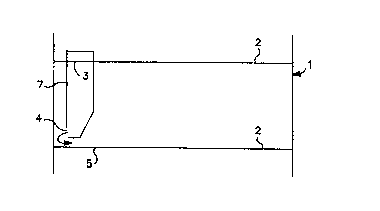
A fractionating column (1) is provided which has perforated fractionating
trays (2) and downcomers (7) allowing liquid to flow from one tray to the tray
immediately below, said downcomers being provided with radial outflow ports
(4) directing downflowing liquids towards the column wall rather than onto the
surface of the tray directly below the downcomer. This permits at least a
portion of the under-downcomer area to be perforated thereby increasing the
capacity of the tray for vapor/liquid contact and ensuring that weeping of the
liquid through the perforations is avoided without need for an increase in
vapor pressure.


French Abstract

L'invention concerne une colonne (1) de fractionnement comprenant des plateaux (2) de fractionnement perforés et des déversoirs (7) permettant l'écoulement d'un liquide d'un plateau vers le plateau placé immédiatement dessous, lesdits déversoirs étant pourvus d'orifices (4) d'écoulement radial envoyant les liquides à courant descendant vers la paroi de la colonne plutôt que sur la surface du plateau immédiatement au-dessous du déversoir. Ceci permet au moins la perforation d'une partie de la zone se trouvant sous le déversoir, ce qui a pour effet d'augmenter la capacité du plateau pour un contact vapeur/liquide et d'éviter l'écoulement du liquide par les perforations, sans avoir à augmenter la pression de vapeur.

Claims

Note: Claims are shown in the official language in which they were submitted.

WHAT IS CLAIMED IS:
1. A fractionating column having an inner wall and
comprising a plurality of horizontally disposed
perforated fractionation trays located one
above the other within said column including a
first perforated fractionation tray with at
least one downcomer located adjacent the
periphery of the tray for channeling an outflow
from the first tray through at least one
radially disposed exit port to a second
perforated fractionation tray directly below
the first, said second tray comprising an
under-downcomer area located directly below the
downcomer from the first fractionation tray,
characterized in that the exit port from each
downcomer is located in such a way that the
outflow therefrom is initially directed
exclusively towards the inner wall of the
column adjacent the downcomer, and at least a
portion of the under-downcomer area of the
second tray is provided with a plurality of
perforations.
2. A fractionating column according to Claim 1
which comprises a perforated barrier between
the perforated area of the second perforated
tray and the area immediately contacted by
liquid exiting the downcomer.
-5-

Description

Note: Descriptions are shown in the official language in which they were submitted.


w ~ ~ CA 02277214 1999-07-08
:'~ ,:.'"~ R
~ACEM~ pAGE
FRACTIONATION TRAYS
Background of the Invention
This invention relates to chemical process~equipment in
which a liquid is contacted with a counterflow of gas. This
may be for a variety of purposes such as stripping a component
from the liquid stream or absorbing a component into a liquid
stream. More generically this invention relates to equipment '
designed to facilitate mass and/or heat transfer between
phases.
The type of equipment to which this invention
specifically relates employs cross-flow fractionation trays
connected by downcomers. In such equipment a tower is provided
i;
with a plurality of fractionation trays arranged generally
horizontally within the tower. Each tower has a perforated
deck and at least one channel, called a downcomer
i
h
,
n w
ich a
,.
liquid flowing over the deck may be collected and channeled to
the tray below. In use a gas or vapor is introduced at the
base of the tower and passes upwards through the perforations
in the decks of the fractionation trays. Meanwhile a liquid is
i
introduced at the top of the tower and percolates downward
'passing over the fractionation trays and down the downcomers to
the tray below. Liquid exits the downcomers in a typical
design either through an open bottom and/or the downcomer front
area, (that is the side facing towards the center of the tray).
In some cases the downcomer may have a bottom pan where liquid
flows around and out through slots in the bottom. In some
i
designs there is provision for a perforated area under the
i downcomer with contact between vapor and liquid precluded by a
box over the perforated portion of the under-downcomer area.
Normally no provision is made for vapor contact with the liquid
;. in the under-downcomer area and this reduces the capacity of
the tower. Scme modifications to address this problem have led
j to the use of slotted bottoms to the downcomers, as in for
example JP-A-7 318 192, to distribute the liquid flow more
evenly in all directions so as to allow perforations of the
under-downcomer area but this is still a problem area from the
point of view of liquid passing directly down through
perforations intended for the upward passage of vapor. In the
apparatus decribed in USP 3,784,175, the outflow from the
downcomer is directed towards the portion of the tray near the
column wall by means of a spring supported curved member that
~ r~,r.~~ 'CJ S C
~~'~IL. V

CA 02277214 1999-07-08
REPLACEMENT PAGE
is responsive to the weight of liquid in the downcomer so as to
open or close the exit to the downcomer in response to such
weight.
According to the ideal process design, the liquid should
be prevented from passing through the perforations in the decks
of the fractionation trays by the pressure of gas passing
through the perforations in the upward direction. This is a
finely balanced process since, if the pressure is too great,
the gas will have a shorter transit time within the tower and
less efficient contact with the down-flowing liquid. The high
gas velocity may also cause liquid droplets to be carried up to
the tray above, thereby reducing the separation efficiency as a
result of back-mixing. On the other hand if the gas flow rate
is too low the liquid will penetrate through the perforations
in the tray decks, (known as "weeping"), and short-circuit the
flow patterns which are intended to maximize liquid/gas
contacts.
Thus, in summary,. the gas flow should be slow enough to
permit efficient contact with the liquid flow but fast enough
~to minimize weeping. While a pressure differential between the
space above a fractionation tray and the space below is
necessary, if this differential is too great gas flow will be
accelerated as it passes through the perforations and the
efficient bubbling contact will be lost. To maintain the same
volume of gas flow but reduce the pressure,~differential it is
necessary. to maximize the perforated area of the fractionation
tray or provide some other efficient mechanism for the gas to
contact the liquid as it passes through the fractionation tray.
Weeping is however often a problem when the liquid flow
rate is particularly heavy in a local perforated area, and
particularly in the under-downcomer area. Therefore to some
extent the desire to attain the greatest contact efficiency,
(which implies the lowest feasible pressure drop across the
tower), by perforating as large a part of the deck surface as
possible is at odds with the desire to avoid weeping. The
present invention provides a high efficiency, (or high
- Z "
.,~~ ~wr--
~'l~il-..Lia.t/ 1 f._-.

CA 02277214 1999-07-08
WO 98132511 PCT/US97/01234
capacity), fractionation tray design that ensures that the
danger of weeping is minimized.
General Description of the Invention
The present invention provides a fractionating column
comprising a first perforated fractionation tray with at least
one downcomer for channeling an outflow from the first tray to
a second perforated fractionation tray directly below the first
in which each downcomer channels downflowing liquid from the
first tray to a portion of the second tray adjacent the
junction of the tray and the column wall. The downcomer
preferably has a restricted exit area designed to ensure that
the outflow therefrom is directed exclusively towards a
peripheral, non-perforated portion of the second tray. Liquid
may, for example, be discharged from the downcomers via radial
slots, rectangular slots, castellated weirs or plain weirs
specifically designed to direct the flow to a wall/tray
junction area from which it can be evenly distributed before
contacting the perforated area of the fractionation tray. It
is found that if the outflow from the downcomer is spread on
the second tray in this manner before it contacts perforations,
it is possible to avoid localized heavy flow situations that
can lead to weeping. From the wall/tray junction the flow is
naturally spread around the wall and enters the perforated
area. Because the flow is initially directed towards the wall,
a substantial portion of the under-downcomer area can now be
perforated either with simple or valued holes, thereby
increasing the efficiency of the trays.
In a preferred embodiment, a perforated barrier separates
the initial fluid contact area from the perforated portion of
the tray such that the flow on to the perforated area is as
evenly distributed as possible.
Drawings
Figure 1 is cross-section of a portion of a tower containing
fractionation trays and a single enclosed downcomer according
to the invention.
3

CA 02277214 1999-07-08
WO 98r32511 PCT/US9'1/01234
Figure 2 is a plan view of the lower of the fractionation trays
shown in Figure 1. Perforations are shown in the under-
downcomer area.
Detailed Description of the Invention
The invention is now further described with reference to
the Drawings which are intended to illustrate the invention but '
are not to be understood as implying any essential limitations
on the scope of the invention.
The device illustrated in Figures 1 and 2 comprises a
vessel, 1, in which two fractionation trays, 2, are located one
above the other in generally horizontal positions. The
fractionation trays are provided ~tith a plurality of
perforations, 6, and a downcomer, 7, having entry port, 3, and
exit port, 4. In Figure 1 only the downcomer for the upper
tray is shown but it is understood that all trays have similar
downcomers though the location is usually at the opposed side
of the tray to that receiving a flow from the downcomer
associated with the tray immediately above. This maximizes the
flow path of the liquid and the opportunities for contact with
the vapor.
Liquid exiting the downcomer through exit port, 4, is
directed to the under-downcomer zone, 5, which is adjacent the
wall of the vessel and is unperforated. From there the liquid
spreads in the manner shown by the arrows in Figure 2 such that
no part of the tray receives enough liquid to lead to weeping
through the perforations in that part.
The above structure is very advantageous since it ensures
that liquid flowing out from the downcomers does not channel
towards perforations in the fractionation tray deck in such
quantities as to prevent vapor flow through the perforations
and cause weeping. Rather by ensuring that the flow first
contacts non-perforated areas and is spread evenly in the
direction of all perforated areas, a uniformly high degree of '
liquid/vapor contact is maintained.
9

Representative Drawing
A single figure which represents the drawing illustrating the invention.
Administrative Status

2024-08-01:As part of the Next Generation Patents (NGP) transition, the Canadian Patents Database (CPD) now contains a more detailed Event History, which replicates the Event Log of our new back-office solution.

Please note that "Inactive:" events refers to events no longer in use in our new back-office solution.

For a clearer understanding of the status of the application/patent presented on this page, the site Disclaimer , as well as the definitions for Patent , Event History , Maintenance Fee  and Payment History  should be consulted.

Event History

Description Date
Application Not Reinstated by Deadline 2002-01-28
Time Limit for Reversal Expired 2002-01-28
Deemed Abandoned - Failure to Respond to Maintenance Fee Notice 2001-01-29
Inactive: Cover page published 1999-09-29
Inactive: First IPC assigned 1999-09-01
Inactive: IPC assigned 1999-09-01
Inactive: Acknowledgment of national entry - RFE 1999-08-18
Letter Sent 1999-08-18
Application Received - PCT 1999-08-13
All Requirements for Examination Determined Compliant 1999-07-08
Request for Examination Requirements Determined Compliant 1999-07-08
Application Published (Open to Public Inspection) 1998-07-30

Abandonment History

Abandonment Date Reason Reinstatement Date
2001-01-29

Maintenance Fee

The last payment was received on 1999-12-30

Note : If the full payment has not been received on or before the date indicated, a further fee may be required which may be one of the following

  • the reinstatement fee;
  • the late payment fee; or
  • additional fee to reverse deemed expiry.

Patent fees are adjusted on the 1st of January every year. The amounts above are the current amounts if received by December 31 of the current year.
Please refer to the CIPO Patent Fees web page to see all current fee amounts.

Fee History

Fee Type Anniversary Year Due Date Paid Date
Request for examination - standard 1999-07-08
Basic national fee - standard 1999-07-08
Registration of a document 1999-07-08
MF (application, 2nd anniv.) - standard 02 1999-01-27 1999-07-08
MF (application, 3rd anniv.) - standard 03 2000-01-27 1999-12-30
Owners on Record

Note: Records showing the ownership history in alphabetical order.

Current Owners on Record
NORTON CHEMICAL PROCESS PRODUCTS CORPORATION
Past Owners on Record
JOHN HARRIS
JOHN R. SAUTER
RICHARD P. HAUSER
Past Owners that do not appear in the "Owners on Record" listing will appear in other documentation within the application.
Documents

To view selected files, please enter reCAPTCHA code :


To view images, click a link in the Document Description column. To download the documents, select one or more checkboxes in the first column and then click the "Download Selected in PDF format (Zip Archive)" or the "Download Selected as Single PDF" button.

List of published and non-published patent-specific documents on the CPD .

If you have any difficulty accessing content, you can call the Client Service Centre at 1-866-997-1936 or send them an e-mail at CIPO Client Service Centre.


Document
Description 
Date
(yyyy-mm-dd) 
Number of pages   Size of Image (KB) 
Description 1999-07-07 4 206
Abstract 1999-07-07 1 42
Claims 1999-07-07 1 32
Drawings 1999-07-07 1 21
Representative drawing 1999-09-23 1 2
Notice of National Entry 1999-08-17 1 233
Courtesy - Certificate of registration (related document(s)) 1999-08-17 1 140
Courtesy - Abandonment Letter (Maintenance Fee) 2001-02-25 1 182
PCT 1999-07-07 14 558