Language selection

Search

Patent 2277465 Summary

Third-party information liability

Some of the information on this Web page has been provided by external sources. The Government of Canada is not responsible for the accuracy, reliability or currency of the information supplied by external sources. Users wishing to rely upon this information should consult directly with the source of the information. Content provided by external sources is not subject to official languages, privacy and accessibility requirements.

Claims and Abstract availability

Any discrepancies in the text and image of the Claims and Abstract are due to differing posting times. Text of the Claims and Abstract are posted:

  • At the time the application is open to public inspection;
  • At the time of issue of the patent (grant).
(12) Patent Application: (11) CA 2277465
(54) English Title: CAPACITIVE GLOW STARTING OF HIGH INTENSITY DISCHARGE LAMPS
(54) French Title: AMORCAGE PAR DECHARGE LUMINESCENTE CAPACITIVE DE LAMPE A DECHARGE A HAUTE INTENSITE
Status: Deemed Abandoned and Beyond the Period of Reinstatement - Pending Response to Notice of Disregarded Communication
Bibliographic Data
(51) International Patent Classification (IPC):
  • H05B 41/14 (2006.01)
  • H01J 61/02 (2006.01)
  • H01J 61/54 (2006.01)
(72) Inventors :
  • SCHOLZ, JOHN A. (United States of America)
(73) Owners :
  • OSRAM SYLVANIA INC.
(71) Applicants :
  • OSRAM SYLVANIA INC. (United States of America)
(74) Agent: SMART & BIGGAR LP
(74) Associate agent:
(45) Issued:
(22) Filed Date: 1999-07-13
(41) Open to Public Inspection: 2000-06-04
Examination requested: 2004-07-13
Availability of licence: N/A
Dedicated to the Public: N/A
(25) Language of filing: English

Patent Cooperation Treaty (PCT): No

(30) Application Priority Data:
Application No. Country/Territory Date
09/205,581 (United States of America) 1998-12-04

Abstracts

English Abstract


An hermetically sealed arc tube which comprises a hollow body having
oppositely
disposed ends aligned along a longitudinal axis and containing an arc
generating and
sustaining medium therein. An electrode is positioned in each end of the
hollow body
and an ionization zone is positioned adjacent to one of the ends and is a part
thereof.
The ionization zone is exposed to an atmosphere different than the arc
generating and
sustaining medium.


Claims

Note: Claims are shown in the official language in which they were submitted.

6
CLAIMS
THE EMBODIMENTS OF THE INVENTION IN WHICH ANY EXCLUSIVE
PROPERTY OR PRIVLEGE IS CLAMED ARE DEFINED AS FOLLOWS:
1. An arc tube for a discharge lamp comprising: an hermetically sealed
hollow body containing an arc generating and sustaining medium therein and
having
first and second ends; an electrode receiving seal extending from each end; an
electrode
structure positioned in each of said seals, each of said electrode structures
comprising a
proximal electrode end projecting into the interior of said hollow body, a
distal end
projecting exteriorly of said seal, and an intermediate section therebetween,
said
intermediate section being sealed in said seal in an hermetic manner; and a
seal
extension attached to a first one of said seals and extending in a direction
away from
said hollow body, said extension comprising a tubular segment substantially
surrounding said distal end of said electrode projecting from said seal at
said first end;
and a starting aid comprising an electrode adjunct affixed to said distal end
of said
electrode projecting from said first end within said tubular segment and an
electrically
conducting member surrounding said tubular segment and being electrically
connected
to the distal end of the electrode structure positioned in said second end.
2. The arc tube of Claim 1 wherein said electrically conducting member
comprises multiple turns of wire.
3. An hermetically sealed arc tube comprising; a hollow body having
oppositely disposed ends aligned along a longitudinal axis and containing an
arc
generating and sustaining medium therein; an electrode in either end of said
hollow
body and an ionization zone positioned adjacent to one of said ends and being
a part
thereof, said ionization zone being exposed to an atmosphere different than
the arc
generating and sustaining medium.

7
4. The arc tube of Claim 1 wherein said electrode adjunct comprises a wire
extending normal to the said distal end of said electrode.
5. The arc tube of Claim 1 wherein said electrode adjunct comprises a wire
extending parallel to said distal end of said electrode.
6. The arc tube of Claim 5 wherein said electrode adjunct has one end
affixed to said electrode and a free second end spaced therefrom.
7. The arc tube of Claim 6 wherein said free end points toward and internal
wall of said tubular segment.
8. The arc tube of Claim 1 wherein said arc tube is surrounded by a shroud
and said tubular segment is part of said shroud.

Description

Note: Descriptions are shown in the official language in which they were submitted.


CA 02277465 1999-07-13
ATT'Y DOCKET NO. 98-1-314
1
CAPACITIVE GLOW STARTING OF HIGH INTENSITY DISCHARGE LAMPS
TECHNICAL FIELD
This invention relates to starting aids and more particularly to starting aids
for high
intensity discharge lamps. It has particular application to high intensity
discharge lamps
fabricated from quartz.
BACKGROUND ART
Starting low wattage (20w to 70w) or even higher wattage high intensity
discharge
lamps often requires the use of glow bottles in addition to a ballast that
supplies a high
1 S voltage pulse to start the lamp. The glow bottles that have been suggested
and
employed contain a partial pressure (< 1 atmosphere) of argon or nitrogen or
other gas
mixtures. They may even include a partial pressure of mercury. These glow
bottles
contain an additional electrical lead that facilitates the "glow" or
ionization of the
contained gases when a sufficient potential is applied thereto. The glass
vessel of the
glow bottle must also be in close proximity to a lead-in of the opposite
potential for the
glow or ionization to occur.
The use,of glow bottles works well in normal environments; however, their use
becomes
a problem as the size of the lamps gets smaller. For example, there is
insufficient room
in the neck region of a PAR20 lamp jacket to permit glow bottle placement.
Also, such
placement would encounter additional problems associated with distortion of
the
projected image or light beam if the glow bottle were placed in an area that
interferes
with the reflector surface or with the Tensing optics of the lamp.
One solution to the problem that has been suggested employs radioactive
krypton 85 as
the arc tube gas fill; however, that solution requires the expense of extra
filtering and
hazardous material licenses.

CA 02277465 1999-07-13
ATT'Y DOCKET NO. 9&1-314
2
DISCLOSURE OF INVENTION
It is, therefore, an object of the invention to obviate the disadvantages of
the prior art.
It is another object of the invention to enhance the starting of high
intensity discharge
lamps.
It is another object of the invention to provide a starting aid for high
intensity discharge
lamps that does not employ hazardous materials
These objects are accomplished, in one aspect of the invention, by the
provision of an
hermetically sealed arc tube which comprises a hollow body having oppositely
disposed
ends aligned along a longitudinal axis and containing an arc generating and
sustaining
medium therein. An electrode is positioned in each end of the hollow body and
an
ionization zone is positioned adjacent to one of the ends and is a part
thereof. The
ionization zone is exposed to an atmosphere different than the arc generating
and
sustaining medium.
In a further embodiment there is provided an arc tube for a discharge lamp
comprising:
an hermetically sealed hollow body containing an arc generating and sustaining
medium
therein and having first and second ends; an electrode receiving seal
extending from
each end; an electrode structure positioned in each of said seals, each of
said electrode
structures comprising a proximal electrode end projecting into the interior of
said
hollow body, a distal end projecting exteriorly of said seal, and an
intermediate section
therebetween, said intermediate section being sealed in said seal in an
hermetic manner;
and a seal extension attached to a first one of said seals and extending in a
direction
away from said hollow body, said extension comprising a tubular segment
substantially
surrounding said distal end of said electrode projecting from said seal at
said first end;
and a starting aid comprising an electrode adjunct affixed to said distal end
of said
electrode projecting from said first end within said tubular segment and an
electrically

CA 02277465 1999-07-13
ATT'Y DOCKET 1V0. 98-1-314
3
conducting member surrounding said tubular segment and being electrically
connected
to the distal end of the electrode structure positioned in said second end.
BRIEF DESCRIPTION OF THE DRAWINGS
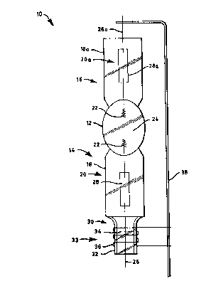
Fig. 1 is an elevational view of an arc tube for a high intensity discharge
lamp using an
embodiment of the invention;
Fig. 2 is a similar view illustrating an alternate embodiment of the
invention; and
Fig. 3 is a similar view illustrating yet another embodiment of the invention.
BEST MODE FOR CARRYING OUT THE INVENTION
For a better understanding of the present invention, together with other and
further
objects, advantages and capabilities thereof, reference is made to the
following
disclosure and appended claims taken in conjunction with the above-described
drawings.
Refernng now to the drawings with greater particularity, there is shown in
Fig. 1 an arc
tube 10 for a discharge lamp. The arc tube comprises an hermetically sealed
hollow
body 12 containing an arc generating and sustaining medium therein and having
first
and second ends, 14, 16. Electrode receiving seals 18, 18a, extend,
respectively, from
the ends, the seals 18, 18a, in this instance, comprising press seals. An
electrode
structure 20 is positioned in seal 18 and an electrode structure 20a is
positioned in seal
18a. Each electrode structure comprises a proximal electrode end 22 that
projects into
the interior 24 of the hollow body 12. Electrode structure 20 has a distal end
26 that
projects exteriorly of the seal 18, and an intermediate section 28. Electrode
structure 20a
has a distal end 26a that projects exteriorly of the seal 18a, and an
intermediate section
28a. The intermediate sections are usually formed of a molybdenum ribbon or
foil

CA 02277465 1999-07-13
ATT'Y DOCKET NO. 9&1-314
4
while the proximal and distal ends are generally tungsten, as is known in the
art. The
hermetic seal is formed between the glass and the molybdenum foil.
A seal extension 30 is attached to one of the ends, for example, first end 14,
and
comprises a tubular segment 32 substantially surrounding the distal end 26 of
electrode
structure 20. A starting aid 33 comprises an electrode adjunct 34, affixed to
the distal
end 26 of the electrode structure 20 within the confines of the tubular
segment, and an
electrically conducting member 36 surrounding the tubular segment 32. The
electrically
conducting member 36 is electrically connected to the distal end 26a of the
electrode
structure 20a positioned in the second end 16, for example, by connector 38.
In a preferred embodiment of the invention, the electrode adjunct 34 is a
piece of 0.015"
diameter molybdenum wire positioned so that the ends are in proximity to the
internal
wall of tubular segment 32 and the electrically conductive member 36 comprises
three
turns of 0.030" diameter nickel wire. The tubing for the tubular segment 32 is
preferably 4.8 mm OD, 3.2 mm ID, leaving a 0.8 mm wall. This configuration
creates
an ionization zone within the tubular segment 32. When power is applied to the
arc tube
from a suitable ballast, an instantaneous glow or ionization of the atmosphere
within the
tubular segment is achieved, this atmosphere being different than the
atmosphere within
the arc tube and, preferably, is air. The radiation from this ionization helps
to start the
arc discharge in the arc tube.
An alternate embodiment of the invention is shown in Fig. 2 wherein the
electrode
adjunct 34a is affixed to the distal end 26 at a location outside of the
tubular segment 32
but extends upwardly into the segment. In this instance, the adjunct 34a has a
termination 40 within the tubular segment, which termination is bent to extend
toward
the internal surface of the tubular segment.
Another embodiment of the invention is shown in Fig. 3 wherein the starting
aid 33 is
incorporated into a shroud 42 that is fixed to the tubular segment 32 or is a
part thereof.

CA 02277465 1999-07-13
ATT'Y DOCKET iVO. 9&1-314
While there have been shown and described what are at present considered the
preferred embodiments of the invention, it will be apparent to those skilled
in the art that
various changes and modifications can be made herein without departing from
the scope
of the invention as defined by the appended claims.
5

Representative Drawing
A single figure which represents the drawing illustrating the invention.
Administrative Status

2024-08-01:As part of the Next Generation Patents (NGP) transition, the Canadian Patents Database (CPD) now contains a more detailed Event History, which replicates the Event Log of our new back-office solution.

Please note that "Inactive:" events refers to events no longer in use in our new back-office solution.

For a clearer understanding of the status of the application/patent presented on this page, the site Disclaimer , as well as the definitions for Patent , Event History , Maintenance Fee  and Payment History  should be consulted.

Event History

Description Date
Application Not Reinstated by Deadline 2008-07-14
Time Limit for Reversal Expired 2008-07-14
Deemed Abandoned - Failure to Respond to Maintenance Fee Notice 2007-07-13
Inactive: IPC from MCD 2006-03-12
Letter Sent 2004-08-09
Request for Examination Received 2004-07-13
All Requirements for Examination Determined Compliant 2004-07-13
Request for Examination Requirements Determined Compliant 2004-07-13
Inactive: Cover page published 2000-06-05
Application Published (Open to Public Inspection) 2000-06-04
Inactive: IPC assigned 1999-09-15
Inactive: First IPC assigned 1999-09-15
Inactive: Filing certificate - No RFE (English) 1999-08-18
Letter Sent 1999-08-18
Application Received - Regular National 1999-08-16

Abandonment History

Abandonment Date Reason Reinstatement Date
2007-07-13

Maintenance Fee

The last payment was received on 2006-06-19

Note : If the full payment has not been received on or before the date indicated, a further fee may be required which may be one of the following

  • the reinstatement fee;
  • the late payment fee; or
  • additional fee to reverse deemed expiry.

Patent fees are adjusted on the 1st of January every year. The amounts above are the current amounts if received by December 31 of the current year.
Please refer to the CIPO Patent Fees web page to see all current fee amounts.

Fee History

Fee Type Anniversary Year Due Date Paid Date
Application fee - standard 1999-07-13
Registration of a document 1999-07-13
MF (application, 2nd anniv.) - standard 02 2001-07-13 2001-06-26
MF (application, 3rd anniv.) - standard 03 2002-07-15 2002-06-21
MF (application, 4th anniv.) - standard 04 2003-07-14 2003-06-20
MF (application, 5th anniv.) - standard 05 2004-07-13 2004-06-25
Request for examination - standard 2004-07-13
MF (application, 6th anniv.) - standard 06 2005-07-13 2005-06-21
MF (application, 7th anniv.) - standard 07 2006-07-13 2006-06-19
Owners on Record

Note: Records showing the ownership history in alphabetical order.

Current Owners on Record
OSRAM SYLVANIA INC.
Past Owners on Record
JOHN A. SCHOLZ
Past Owners that do not appear in the "Owners on Record" listing will appear in other documentation within the application.
Documents

To view selected files, please enter reCAPTCHA code :


To view images, click a link in the Document Description column (Temporarily unavailable). To download the documents, select one or more checkboxes in the first column and then click the "Download Selected in PDF format (Zip Archive)" or the "Download Selected as Single PDF" button.

List of published and non-published patent-specific documents on the CPD .

If you have any difficulty accessing content, you can call the Client Service Centre at 1-866-997-1936 or send them an e-mail at CIPO Client Service Centre.

({010=All Documents, 020=As Filed, 030=As Open to Public Inspection, 040=At Issuance, 050=Examination, 060=Incoming Correspondence, 070=Miscellaneous, 080=Outgoing Correspondence, 090=Payment})


Document
Description 
Date
(yyyy-mm-dd) 
Number of pages   Size of Image (KB) 
Representative drawing 2000-05-25 1 7
Description 1999-07-12 5 197
Abstract 1999-07-12 1 14
Claims 1999-07-12 2 64
Drawings 1999-07-12 3 45
Courtesy - Certificate of registration (related document(s)) 1999-08-17 1 140
Filing Certificate (English) 1999-08-17 1 175
Reminder of maintenance fee due 2001-03-13 1 112
Reminder - Request for Examination 2004-03-15 1 116
Acknowledgement of Request for Examination 2004-08-08 1 177
Courtesy - Abandonment Letter (Maintenance Fee) 2007-09-09 1 177