Sélection de la langue

Search

Sommaire du brevet 2277465 

Énoncé de désistement de responsabilité concernant l'information provenant de tiers

Une partie des informations de ce site Web a été fournie par des sources externes. Le gouvernement du Canada n'assume aucune responsabilité concernant la précision, l'actualité ou la fiabilité des informations fournies par les sources externes. Les utilisateurs qui désirent employer cette information devraient consulter directement la source des informations. Le contenu fourni par les sources externes n'est pas assujetti aux exigences sur les langues officielles, la protection des renseignements personnels et l'accessibilité.

Disponibilité de l'Abrégé et des Revendications

L'apparition de différences dans le texte et l'image des Revendications et de l'Abrégé dépend du moment auquel le document est publié. Les textes des Revendications et de l'Abrégé sont affichés :

  • lorsque la demande peut être examinée par le public;
  • lorsque le brevet est émis (délivrance).
(12) Demande de brevet: (11) CA 2277465
(54) Titre français: AMORCAGE PAR DECHARGE LUMINESCENTE CAPACITIVE DE LAMPE A DECHARGE A HAUTE INTENSITE
(54) Titre anglais: CAPACITIVE GLOW STARTING OF HIGH INTENSITY DISCHARGE LAMPS
Statut: Réputée abandonnée et au-delà du délai pour le rétablissement - en attente de la réponse à l’avis de communication rejetée
Données bibliographiques
(51) Classification internationale des brevets (CIB):
  • H05B 41/14 (2006.01)
  • H01J 61/02 (2006.01)
  • H01J 61/54 (2006.01)
(72) Inventeurs :
  • SCHOLZ, JOHN A. (Etats-Unis d'Amérique)
(73) Titulaires :
  • OSRAM SYLVANIA INC.
(71) Demandeurs :
  • OSRAM SYLVANIA INC. (Etats-Unis d'Amérique)
(74) Agent: SMART & BIGGAR LP
(74) Co-agent:
(45) Délivré:
(22) Date de dépôt: 1999-07-13
(41) Mise à la disponibilité du public: 2000-06-04
Requête d'examen: 2004-07-13
Licence disponible: S.O.
Cédé au domaine public: S.O.
(25) Langue des documents déposés: Anglais

Traité de coopération en matière de brevets (PCT): Non

(30) Données de priorité de la demande:
Numéro de la demande Pays / territoire Date
09/205,581 (Etats-Unis d'Amérique) 1998-12-04

Abrégés

Abrégé anglais


An hermetically sealed arc tube which comprises a hollow body having
oppositely
disposed ends aligned along a longitudinal axis and containing an arc
generating and
sustaining medium therein. An electrode is positioned in each end of the
hollow body
and an ionization zone is positioned adjacent to one of the ends and is a part
thereof.
The ionization zone is exposed to an atmosphere different than the arc
generating and
sustaining medium.

Revendications

Note : Les revendications sont présentées dans la langue officielle dans laquelle elles ont été soumises.


6
CLAIMS
THE EMBODIMENTS OF THE INVENTION IN WHICH ANY EXCLUSIVE
PROPERTY OR PRIVLEGE IS CLAMED ARE DEFINED AS FOLLOWS:
1. An arc tube for a discharge lamp comprising: an hermetically sealed
hollow body containing an arc generating and sustaining medium therein and
having
first and second ends; an electrode receiving seal extending from each end; an
electrode
structure positioned in each of said seals, each of said electrode structures
comprising a
proximal electrode end projecting into the interior of said hollow body, a
distal end
projecting exteriorly of said seal, and an intermediate section therebetween,
said
intermediate section being sealed in said seal in an hermetic manner; and a
seal
extension attached to a first one of said seals and extending in a direction
away from
said hollow body, said extension comprising a tubular segment substantially
surrounding said distal end of said electrode projecting from said seal at
said first end;
and a starting aid comprising an electrode adjunct affixed to said distal end
of said
electrode projecting from said first end within said tubular segment and an
electrically
conducting member surrounding said tubular segment and being electrically
connected
to the distal end of the electrode structure positioned in said second end.
2. The arc tube of Claim 1 wherein said electrically conducting member
comprises multiple turns of wire.
3. An hermetically sealed arc tube comprising; a hollow body having
oppositely disposed ends aligned along a longitudinal axis and containing an
arc
generating and sustaining medium therein; an electrode in either end of said
hollow
body and an ionization zone positioned adjacent to one of said ends and being
a part
thereof, said ionization zone being exposed to an atmosphere different than
the arc
generating and sustaining medium.

7
4. The arc tube of Claim 1 wherein said electrode adjunct comprises a wire
extending normal to the said distal end of said electrode.
5. The arc tube of Claim 1 wherein said electrode adjunct comprises a wire
extending parallel to said distal end of said electrode.
6. The arc tube of Claim 5 wherein said electrode adjunct has one end
affixed to said electrode and a free second end spaced therefrom.
7. The arc tube of Claim 6 wherein said free end points toward and internal
wall of said tubular segment.
8. The arc tube of Claim 1 wherein said arc tube is surrounded by a shroud
and said tubular segment is part of said shroud.

Description

Note : Les descriptions sont présentées dans la langue officielle dans laquelle elles ont été soumises.

CA 02277465 1999-07-13
ATT'Y DOCKET NO. 98-1-314
1
CAPACITIVE GLOW STARTING OF HIGH INTENSITY DISCHARGE LAMPS
TECHNICAL FIELD
This invention relates to starting aids and more particularly to starting aids
for high
intensity discharge lamps. It has particular application to high intensity
discharge lamps
fabricated from quartz.
BACKGROUND ART
Starting low wattage (20w to 70w) or even higher wattage high intensity
discharge
lamps often requires the use of glow bottles in addition to a ballast that
supplies a high
1 S voltage pulse to start the lamp. The glow bottles that have been suggested
and
employed contain a partial pressure (< 1 atmosphere) of argon or nitrogen or
other gas
mixtures. They may even include a partial pressure of mercury. These glow
bottles
contain an additional electrical lead that facilitates the "glow" or
ionization of the
contained gases when a sufficient potential is applied thereto. The glass
vessel of the
glow bottle must also be in close proximity to a lead-in of the opposite
potential for the
glow or ionization to occur.
The use,of glow bottles works well in normal environments; however, their use
becomes
a problem as the size of the lamps gets smaller. For example, there is
insufficient room
in the neck region of a PAR20 lamp jacket to permit glow bottle placement.
Also, such
placement would encounter additional problems associated with distortion of
the
projected image or light beam if the glow bottle were placed in an area that
interferes
with the reflector surface or with the Tensing optics of the lamp.
One solution to the problem that has been suggested employs radioactive
krypton 85 as
the arc tube gas fill; however, that solution requires the expense of extra
filtering and
hazardous material licenses.

CA 02277465 1999-07-13
ATT'Y DOCKET NO. 9&1-314
2
DISCLOSURE OF INVENTION
It is, therefore, an object of the invention to obviate the disadvantages of
the prior art.
It is another object of the invention to enhance the starting of high
intensity discharge
lamps.
It is another object of the invention to provide a starting aid for high
intensity discharge
lamps that does not employ hazardous materials
These objects are accomplished, in one aspect of the invention, by the
provision of an
hermetically sealed arc tube which comprises a hollow body having oppositely
disposed
ends aligned along a longitudinal axis and containing an arc generating and
sustaining
medium therein. An electrode is positioned in each end of the hollow body and
an
ionization zone is positioned adjacent to one of the ends and is a part
thereof. The
ionization zone is exposed to an atmosphere different than the arc generating
and
sustaining medium.
In a further embodiment there is provided an arc tube for a discharge lamp
comprising:
an hermetically sealed hollow body containing an arc generating and sustaining
medium
therein and having first and second ends; an electrode receiving seal
extending from
each end; an electrode structure positioned in each of said seals, each of
said electrode
structures comprising a proximal electrode end projecting into the interior of
said
hollow body, a distal end projecting exteriorly of said seal, and an
intermediate section
therebetween, said intermediate section being sealed in said seal in an
hermetic manner;
and a seal extension attached to a first one of said seals and extending in a
direction
away from said hollow body, said extension comprising a tubular segment
substantially
surrounding said distal end of said electrode projecting from said seal at
said first end;
and a starting aid comprising an electrode adjunct affixed to said distal end
of said
electrode projecting from said first end within said tubular segment and an
electrically

CA 02277465 1999-07-13
ATT'Y DOCKET 1V0. 98-1-314
3
conducting member surrounding said tubular segment and being electrically
connected
to the distal end of the electrode structure positioned in said second end.
BRIEF DESCRIPTION OF THE DRAWINGS
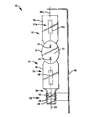
Fig. 1 is an elevational view of an arc tube for a high intensity discharge
lamp using an
embodiment of the invention;
Fig. 2 is a similar view illustrating an alternate embodiment of the
invention; and
Fig. 3 is a similar view illustrating yet another embodiment of the invention.
BEST MODE FOR CARRYING OUT THE INVENTION
For a better understanding of the present invention, together with other and
further
objects, advantages and capabilities thereof, reference is made to the
following
disclosure and appended claims taken in conjunction with the above-described
drawings.
Refernng now to the drawings with greater particularity, there is shown in
Fig. 1 an arc
tube 10 for a discharge lamp. The arc tube comprises an hermetically sealed
hollow
body 12 containing an arc generating and sustaining medium therein and having
first
and second ends, 14, 16. Electrode receiving seals 18, 18a, extend,
respectively, from
the ends, the seals 18, 18a, in this instance, comprising press seals. An
electrode
structure 20 is positioned in seal 18 and an electrode structure 20a is
positioned in seal
18a. Each electrode structure comprises a proximal electrode end 22 that
projects into
the interior 24 of the hollow body 12. Electrode structure 20 has a distal end
26 that
projects exteriorly of the seal 18, and an intermediate section 28. Electrode
structure 20a
has a distal end 26a that projects exteriorly of the seal 18a, and an
intermediate section
28a. The intermediate sections are usually formed of a molybdenum ribbon or
foil

CA 02277465 1999-07-13
ATT'Y DOCKET NO. 9&1-314
4
while the proximal and distal ends are generally tungsten, as is known in the
art. The
hermetic seal is formed between the glass and the molybdenum foil.
A seal extension 30 is attached to one of the ends, for example, first end 14,
and
comprises a tubular segment 32 substantially surrounding the distal end 26 of
electrode
structure 20. A starting aid 33 comprises an electrode adjunct 34, affixed to
the distal
end 26 of the electrode structure 20 within the confines of the tubular
segment, and an
electrically conducting member 36 surrounding the tubular segment 32. The
electrically
conducting member 36 is electrically connected to the distal end 26a of the
electrode
structure 20a positioned in the second end 16, for example, by connector 38.
In a preferred embodiment of the invention, the electrode adjunct 34 is a
piece of 0.015"
diameter molybdenum wire positioned so that the ends are in proximity to the
internal
wall of tubular segment 32 and the electrically conductive member 36 comprises
three
turns of 0.030" diameter nickel wire. The tubing for the tubular segment 32 is
preferably 4.8 mm OD, 3.2 mm ID, leaving a 0.8 mm wall. This configuration
creates
an ionization zone within the tubular segment 32. When power is applied to the
arc tube
from a suitable ballast, an instantaneous glow or ionization of the atmosphere
within the
tubular segment is achieved, this atmosphere being different than the
atmosphere within
the arc tube and, preferably, is air. The radiation from this ionization helps
to start the
arc discharge in the arc tube.
An alternate embodiment of the invention is shown in Fig. 2 wherein the
electrode
adjunct 34a is affixed to the distal end 26 at a location outside of the
tubular segment 32
but extends upwardly into the segment. In this instance, the adjunct 34a has a
termination 40 within the tubular segment, which termination is bent to extend
toward
the internal surface of the tubular segment.
Another embodiment of the invention is shown in Fig. 3 wherein the starting
aid 33 is
incorporated into a shroud 42 that is fixed to the tubular segment 32 or is a
part thereof.

CA 02277465 1999-07-13
ATT'Y DOCKET iVO. 9&1-314
While there have been shown and described what are at present considered the
preferred embodiments of the invention, it will be apparent to those skilled
in the art that
various changes and modifications can be made herein without departing from
the scope
of the invention as defined by the appended claims.
5

Dessin représentatif
Une figure unique qui représente un dessin illustrant l'invention.
États administratifs

2024-08-01 : Dans le cadre de la transition vers les Brevets de nouvelle génération (BNG), la base de données sur les brevets canadiens (BDBC) contient désormais un Historique d'événement plus détaillé, qui reproduit le Journal des événements de notre nouvelle solution interne.

Veuillez noter que les événements débutant par « Inactive : » se réfèrent à des événements qui ne sont plus utilisés dans notre nouvelle solution interne.

Pour une meilleure compréhension de l'état de la demande ou brevet qui figure sur cette page, la rubrique Mise en garde , et les descriptions de Brevet , Historique d'événement , Taxes périodiques et Historique des paiements devraient être consultées.

Historique d'événement

Description Date
Demande non rétablie avant l'échéance 2008-07-14
Le délai pour l'annulation est expiré 2008-07-14
Réputée abandonnée - omission de répondre à un avis sur les taxes pour le maintien en état 2007-07-13
Inactive : CIB de MCD 2006-03-12
Lettre envoyée 2004-08-09
Requête d'examen reçue 2004-07-13
Toutes les exigences pour l'examen - jugée conforme 2004-07-13
Exigences pour une requête d'examen - jugée conforme 2004-07-13
Inactive : Page couverture publiée 2000-06-05
Demande publiée (accessible au public) 2000-06-04
Inactive : CIB attribuée 1999-09-15
Inactive : CIB en 1re position 1999-09-15
Inactive : Certificat de dépôt - Sans RE (Anglais) 1999-08-18
Lettre envoyée 1999-08-18
Demande reçue - nationale ordinaire 1999-08-16

Historique d'abandonnement

Date d'abandonnement Raison Date de rétablissement
2007-07-13

Taxes périodiques

Le dernier paiement a été reçu le 2006-06-19

Avis : Si le paiement en totalité n'a pas été reçu au plus tard à la date indiquée, une taxe supplémentaire peut être imposée, soit une des taxes suivantes :

  • taxe de rétablissement ;
  • taxe pour paiement en souffrance ; ou
  • taxe additionnelle pour le renversement d'une péremption réputée.

Les taxes sur les brevets sont ajustées au 1er janvier de chaque année. Les montants ci-dessus sont les montants actuels s'ils sont reçus au plus tard le 31 décembre de l'année en cours.
Veuillez vous référer à la page web des taxes sur les brevets de l'OPIC pour voir tous les montants actuels des taxes.

Historique des taxes

Type de taxes Anniversaire Échéance Date payée
Taxe pour le dépôt - générale 1999-07-13
Enregistrement d'un document 1999-07-13
TM (demande, 2e anniv.) - générale 02 2001-07-13 2001-06-26
TM (demande, 3e anniv.) - générale 03 2002-07-15 2002-06-21
TM (demande, 4e anniv.) - générale 04 2003-07-14 2003-06-20
TM (demande, 5e anniv.) - générale 05 2004-07-13 2004-06-25
Requête d'examen - générale 2004-07-13
TM (demande, 6e anniv.) - générale 06 2005-07-13 2005-06-21
TM (demande, 7e anniv.) - générale 07 2006-07-13 2006-06-19
Titulaires au dossier

Les titulaires actuels et antérieures au dossier sont affichés en ordre alphabétique.

Titulaires actuels au dossier
OSRAM SYLVANIA INC.
Titulaires antérieures au dossier
JOHN A. SCHOLZ
Les propriétaires antérieurs qui ne figurent pas dans la liste des « Propriétaires au dossier » apparaîtront dans d'autres documents au dossier.
Documents

Pour visionner les fichiers sélectionnés, entrer le code reCAPTCHA :


Pour visualiser une image, cliquer sur un lien dans la colonne description du document (Temporairement non-disponible). Pour télécharger l'image (les images), cliquer l'une ou plusieurs cases à cocher dans la première colonne et ensuite cliquer sur le bouton "Télécharger sélection en format PDF (archive Zip)" ou le bouton "Télécharger sélection (en un fichier PDF fusionné)".

Liste des documents de brevet publiés et non publiés sur la BDBC .

Si vous avez des difficultés à accéder au contenu, veuillez communiquer avec le Centre de services à la clientèle au 1-866-997-1936, ou envoyer un courriel au Centre de service à la clientèle de l'OPIC.

({010=Tous les documents, 020=Au moment du dépôt, 030=Au moment de la mise à la disponibilité du public, 040=À la délivrance, 050=Examen, 060=Correspondance reçue, 070=Divers, 080=Correspondance envoyée, 090=Paiement})


Description du
Document 
Date
(aaaa-mm-jj) 
Nombre de pages   Taille de l'image (Ko) 
Dessin représentatif 2000-05-25 1 7
Description 1999-07-12 5 197
Abrégé 1999-07-12 1 14
Revendications 1999-07-12 2 64
Dessins 1999-07-12 3 45
Courtoisie - Certificat d'enregistrement (document(s) connexe(s)) 1999-08-17 1 140
Certificat de dépôt (anglais) 1999-08-17 1 175
Rappel de taxe de maintien due 2001-03-13 1 112
Rappel - requête d'examen 2004-03-15 1 116
Accusé de réception de la requête d'examen 2004-08-08 1 177
Courtoisie - Lettre d'abandon (taxe de maintien en état) 2007-09-09 1 177