Note: Descriptions are shown in the official language in which they were submitted.
CA 02277524 1999-07-13
A METHOD AND APPARATUS FOR ADJUSTING THE COUPLING REACTANCES
BETWEEN TWISTED PAIRS FOR ACHIEVING A DESIRED LEVEL OF
CROSSTALK
Field of the Invention
The present invention relates to high-speed data communication cables. More
particularly, it relates to a high-speed data communication cable with
adjustable coupling
reactances between the twisted pairs within a cable to establish a known,
consistent, and
repeatable crosstalk level between the twisted pairs within a cable.
Related Art
High speed data communications cables in current usage include pairs of wire
twisted
together forming a balanced transmission line. Such pairs of wire are referred
to as twisted
pairs.
One common type of conventional cable for high-speed data communications
includes
multiple twisted pairs within it. In each twisted pair, the wires are twisted
together in a
helical fashion, thus forming a balanced transmission line. Twisted pairs that
are placed in
close proximity, such as within a cable, may transfer electrical energy from
one pair of the
cable to another. Such energy transfer between pairs is undesirable and is
referred to as
2o crosstalk. Crosstalk is electromagnetic noise coupled to a twisted pair
from an adjacent
twisted pair, or from an adjacent cable. Telecommunications systems contain
noise that
interferes with the transmission of information. Crosstalk increases the
interference to the
information being transmitted through the twisted pair. The increased
interference due to
crosstalk can cause an increase in the occurrence of data transmission errors
and a
concomitant decrease in the data transmission rate. The Telecommunications
Industry
Association (TIA) and Electronics Industry Association (EIA) have defined
standards for
crosstalk in a data communications cable that include: TIA/EIA 568-A-2,
published August
14, 1998. The International Electrotechnical Commission (IEC) has also defined
standards
for data communications cable crosstalk, including ISO/IEC 11801 that is the
international
3o equivalent to TIA/EIA 568-A. One high performance standard for data
communications cable
is ISO/IEC 11801, Category 5.
CA 02277524 1999-07-13
-2-
Crosstalk is primarily capacitively coupled or inductively coupled energy
passing
between adjacent twisted pairs within a cable. Among the factors that
determine the amount
of crosstalk energy coupled between the wires in adjacent twisted pairs, the
center-to-center
distance between the wires in the adjacent twisted pairs is very important.
The center-to-
center distance is defined herein to be the distance between the center of one
wire of a twisted
pair to the center of another wire in an adjacent twisted pair. The magnitude
of both
capacitively coupled and inductively coupled crosstalk is inversely
proportional to the center-
to-center distance between wires. Increasing the distance between twisted
pairs can thus
reduce the level of crosstalk interference. Another factor relating to the
level of crosstalk is
1o the distance over which the wires run parallel to one another. Twisted
pairs that have longer
parallel runs typically have higher levels of crosstalk occurring between
them.
In twisted pairs, the rate of the twist is known as the twist lay, and it is
the distance
between adjacent twists of the wire. The direction of the twist of a twisted
pair is known as
the twist direction. Adjacent twisted pairs having the same twist lay and/or
opposing twist
directions tend to lie more closely together within a cable than if they have
different twist lays
and/or same twist directions. Thus, compared to twisted pairs having different
twist lays
and/or same twist directions, adjacent twisted pairs having the same twist lay
and opposing
directions have a reduced center-to-center distance, and longer parallel run.
Therefore, the
level of crosstalk energy coupled between the wires in adjacent twisted pairs
tends to be
2o higher between twisted pairs that have the same twist lay and/or opposing
directions as
compared to other twisted pairs that have different twist lays and/or same
twist directions.
Thus, the unique twist lay serves to decrease the level of crosstalk between
the adjacent
twisted pairs within the cable. Therefore, twisted pairs within a cable are
sometimes given
unique twist lays when compared to other adjacent twisted pairs within the
cable.
As the continuous twisted or helical structure reaches a termination point,
for example
as the cable is terminated to be joined to a connector, the helical structures
of the individual
twisted pairs are deformed to mate with contacts in the terminating hardware
creating a de-
twisted region within the cable. The actual angle of arrival of the helix of
the individual
twisted pairs in relation to the mating hardware depends on where the cable is
cut within its
length. Therefore, the amount of deformation required to align the conductors
of the wire pair
with the connection points can vary from twisted pair to twisted pair within a
cable. The
random nature of the deformation of the helical structure creates undesirable
inter-pair
CA 02277524 1999-07-13
-3-
coupling variations from one connector to the next. Therefore, although the
unique twist lay
and twist direction can reduce the level of crosstalk within the cable, the de-
twisting action
produces a level of crosstalk that tends to be random.
In an attempt to reach cross-manufacturer compatibility, EIA/TIA mandates a
known
coupling level in category 5 mating hardware. Mating hardware is designed, via
counter-
coupling, to compensate for the mandated coupling level in order to establish
a predetermined
level of coupling in a data communications link over a category 5 cable. The
variability in the
inter-pair coupling encountered from one plug to the next serves to limit the
effectiveness of
the counter-coupling compensation.
1o This specified, standard level of coupling within the mating hardware is
provided so
that overall the system can have a level of crosstalk that ensures that the
particular
transmission standard is properly met. Although it is possible to reduce the
actual amount of
coupling in the mating hardware to improve overall performance, this is not
desirable in order
to be in compliance with the appropriate standards and reverse compatibility
reasons as well.
15 What is preferable is a constant, repeatable and known level of crosstalk.
If a category 5 plug
is connected to a superior performance jack, it is expected that the plug and
jack will be able
to meet category 5 coupling specifications. This means that the jack/plug must
be able to
counter-couple for the level of coupling specified for a category 5 plug/jack.
In addition, if
two superior performance connectors are used, it is reasonable to expect that
the superior
2o performance mating hardware is able to counter-couple for the level of
coupling specified for
the superior performance hardware.
It is desirable for the crosstalk occurring in the region adjacent to where
the twisted
pairs have exited from the cable be of a known, consistent, repeatable, and
standard value in
order to mate with the connecting hardware. At least part of the region is
herein referred to as
25 the "detwisted" portion of the cable. Various conventional methods have
been used in an
attempt to improve the consistency of counter-coupling within the cable and
jack or plug. For
example, the use of shielded connectors, lead frames, and complex electronic
counter-
coupling have been used. However, these methods often increase the time
required for
installation, may require special tools, and can increase the material cost
due to a larger parts
3o count. This may lead to market acceptance problems due to the increased
costs associated
with the special tooling and the additional training required.
CA 02277524 1999-07-13
-4-
Summar~r of the Invention
The present invention provides an improved method and apparatus for creating
consistent, known, and repeatable levels of crosstalk between twisted pairs
within a data cable
by adjusting the coupling reactances between twisted pairs.
According to one aspect, the apparatus for adjusting the coupling reactances
includes a
cable having a plurality of twisted pairs. The cable has a de-twisted region
where the twisted
pairs transition from a twisted configuration to an untwisted configuration
and are arranged in
a predetermined configuration. An isolation element is located in the de-
twisted region of the
cable controlling the coupling between adjacent pairs.
1 o In one embodiment, the isolation element may be constructed of a
dielectric material, a
conductive material, or a ferromagnetic material. In another embodiment, the
present
invention may also include an isolation element having a window defined
therethrough for
selectively adjusting the coupling reactances between the twisted pairs within
the cable. In
another embodiment, the isolation element may have a nonhomogeneous dielectric
constant
over its length to vary the electrical thickness of the isolation element.
Alternatively, the
isolation element may vary in its physical thickness over its length, and/or
the dielectric
constant of the material may vary over its length to vary the electrical
thickness of the
isolation element. In another embodiment of the present invention, the
isolation element may
have a pattern of features including gaps for adjusting the coupling
reactances between the
2o twisted pairs within the cable.
In another aspect of the present invention a cable having a standard level of
crosstalk
relative to a conventional cable is disclosed. The cable has a plurality of
twisted pairs and de-
twisted region where the twisted pairs transition from a twisted configuration
to an untwisted
configuration and arranged for mating with associated mating hardware. In one
embodiment,
a means for isolating the two wires comprising one of the plurality of the
twisted pairs from
the two wires comprising an adjacent twisted pair, and for adjusting the
coupling reactances
within the de-twisted region of the cable to achieve a desired level of
crosstalk between the
twisted pairs is disclosed. In one embodiment, the means for isolating may
include an
isolation element that can have at least one window defined therethrough. The
window or
3o windows are sized and arranged for creating and adjusting coupling
reactances between the
adjacent twisted pairs.
CA 02277524 1999-07-13
-5-
In another aspect of the present invention a terminated cable having a desired
level of
crosstalk and controlling crosstalk characteristics is disclosed. The cable
has a plurality of
twisted pairs and a de-twisted region where the twisted wire transitions from
a twisted
configuration to an untwisted configuration and are linearly arranged. The
cable may include
a means for creating a larger center-to-center distance between a wire of one
twisted pair and a
wire of an adjacent twisted pairs. The means for creating a larger center-to-
center distance
include an isolation element having a varying thickness and/or a varying
dielectric constant.
In another aspect of the invention, a cable having a repeatable level of
crosstalk
terminated with mating hardware includes a plurality of twisted pairs of
conductors, that exit
1 o from the cable into a first region adjacent to the exit region of the
cable, and an isolation
element having top and bottom surfaces, and an end region distal to the exit
region of the
cable, and constructed and arranged to physically separate and at least
partially electrically
isolate individual twisted pairs from one another, and a second region
adjacent to the end
region of the isolation element, wherein each twisted pair is detwisted and
oriented to
1 s electrically mate with the mating hardware.
In one embodiment, the isolation element includes a plurality of main channels
on
the top surface of isolation element and at least one main channel on the
bottom surface of the
isolation element, wherein each of the plurality of twisted pairs are disposed
within a single
main channel. In another embodiment, the main channels have two sub-channels
and have a
20 ridge vertically extending between them forming the two sub-channels into a
W shape with
each sub-channel containing one wire of a twisted pair.
In another embodiment, the isolation element can include a laminated structure
with at
least first, second, and third layers. In one embodiment, the first layer is a
conductor and the
second and third layers are dielectric materials. In one embodiment, the first
layer is
2s composed of stainless steel, and in another embodiment, the second and
third layers are
composed of Mylar~ tape. Mylar~, as used herein, includes polyester film in
general that
retains good physical properties over a wide temperature range, has a high
tensile tear and
impact strength, is inert to water, is moisture-vapor resistant and is
unaffected and does not
transmit oils, greases, or volatile arromaties. In particular, one form of
polyester can be
3o polyethylene terephthalate. In another embodiment, the first layer of the
laminated structure
is at virtual ground with respect to the plurality of twisted pairs.
CA 02277524 2000-12-11
64317-178(S)
6
In another embodiment, the plurality of twisted pairs
of conductors have a distance between adjacent twists of the
wire equal to a twist lay and the first region has a length
between one-half and one twist lays.
In accordance with the present invention, there is
provided a terminated cable having a desired crosstalk level
comprising: a cable havir~g a plura=Lity of twisted pairs, the
twisted pairs each hav.in.g two insulated conductors, the cable
having an exit region where the twisted pairs exit the cable; a
de-twisted region transversely adjacent to the exit region
wherein the twisted pair's transition into an untwisted
configuration and arranged to mate with connecting hardware; an
isolation element located in the de-twisted region of the
cable, the isolation element controlling the coupling between
adjacent pairs.
In accordance with the present invention, there is
provided, a terminated cable having a desired crosstalk
relative to a conventional cable comprising: a cable having a
plurality of twisted pairs, the twisted pairs each having two
insulated conductors; the cable further having a de-twisted
region wherein the twisted pairs transition into an untwisted
configuration and arrancred to mate with connecting hardware; a
means for isolating the t:wo wires of one of the plurality of
the twisted pairs from the two wires of another plurality of
twisted pairs, wherein in the means for isolating also adjusts
the coupling reactances within the de-twisted region of the
cable between the linearly adjacent individual conductors;
whereby the desired leve~7_ of crosstalk between the twisted
pairs is achieved.
In accordance with the present invention, there is
provided a terminated cable having a desired level of crosstalk
relative to a conventional cable comprising: a cable having a
CA 02277524 2000-12-11
64317-178(S)
6a
plurality of twisted pairs, the twisted pairs each having two
insulated conductors; t=he cable further having a de-twisted
region transition into an untwisted configuration and arranged
to mate with connecting hardware; means for creating a larger
center-to-center distance between two wires of one of the
plurality of twisted pairs from the two wires of another of the
plurality of twisted pairs than the insulation of each wire
provides within the de-twisted region of the cable; whereby
electromagnetic couplir~c~ is adjusted between the individual
insulated conductors ar..d the desired level of crosstalk is
achieved.
In accordance with the present invention, there is
further provided a cable having a repeatable level of crosstalk
terminated with mating hardware, the cable comprising: a cable
containing a plurality of twisted pairs of conductors; the
cable having an exit region wherein the plurality of twisted
pairs exit from the cable; a first region adjacent to the exit
region of the cable; an isolation element having top and bottom
surfaces, an end region distal to the exit region of the cable,
and constructed and arr~~nged to physically separate and at
least partially electrically isolate each twisted pair from one
another; a second region adjacent to the end region of the
isolation element, wherf=in each twisted pair is detwisted and
oriented to electricall~~ mate with the mating hardware.
Brief Description of the Drawings
In the drawings in which like reference numerals
designate like elements:
Fig. 1 is top view of a cable and an isolation
element according to one embodiment of the invention;
CA 02277524 2000-12-11
64317-178(S)
6b
Fig. 2 is a cross-sectional view of the cable and
isolation element according to the embodiment of Fig. 1 taken
along line 2-2 in Fig. :L;
Fig. 3 is a longitudinal cross-sectional view of a
cable and isolation elernent according to another embodiment of
the present invention;
Fig. 4 is a cross-sectional view of a cable and
isolation element according to the embodiment of the invention
shown in Fig. 3 taken along line 3-3 in Fig. 3;
Fig. 5 is a longitudinal cross-sectional view of
another embodiment of the present invention;
Fig. 6 is a cross-sectional view of a cable and
isolation element according to the embodiment of the invention
in Fig. 5 taken along lire 6-6 in Fig. 5;
Fig. 7 is top view of a cable and an isolation
element according to one embodiment of the invention;
Fig. 8 is a cross sectional view of the isolation
element according to one embodiment of the present invention;
Fig. 9 is a front view of the isolation element
according to the embodiment of Fig. 7 taken along line 9-9 in
Fig. 7;
Fig. 10 is an exploded view of a cable according to
one embodiment. of the invention; and
Fig. 11 is an exploded view of an isolation element
according to one embodiment of the invention.
CA 02277524 2000-12-11
64317-178(S)
6c
Detailed Description
Generally, the present invention adjusts the coupling
reactances between twisi~ed pairs within a cable to establish a
known level of crosstalk. An isolation element that is in a
CA 02277524 1999-07-13
detwisted region of the cable adjusts the coupling reactances. The isolation
element separates
and, at least partially isolates electrically, at least two wires in adjacent
twisted pairs within
the cable. The isolation element generally may be constructed from dielectric,
conductive or
ferromagnetic materials. The isolation element may have a pattern having
multiple openings,
or a single window defined therethrough, to allow coupling of electric,
magnetic or
electromagnetic fields between various wires within the cable. The windows and
openings
may establish a desired level of crosstalk between the wires.
The present invention may be implemented in generally any cable utilizing
twisted
pairs. However, the illustrated embodiments of the present invention are shown
particularly
1 o for a cable containing four separate twisted pairs. The inventive
principles of the present
invention can be applied to cables including greater or fewer numbers of
twisted pairs
according to the present invention.
Fig. 1 is a top view of one embodiment of the present invention for adjusting
the
coupling reactances 100 in a cable 102. Cable 102 in the illustrated
embodiment comprises
15 multiple twisted pairs of insulated conductors 104 contained within a cable
jacket 106. Cable
102 further contains a detwisted region 108 where the twisted pairs 104 exit
from the cable
jacket and transition to an arrangement suitable for mating with a piece of
mating hardware
(not shown). Mating hardware or connectors as used herein include plugs,
jacks, punch down
blocks, or any connection techniques used by those of ordinary skill in the
art when
2o interconnecting telecommunications cables. An isolation element 110 is
configured within
the detwisted region 108 of cable 102. The isolation element 110 separates the
two wires of
one twisted pair from the two wires of another twisted pair contained within
the cable.
Fig. 2 shows a cross section of the present invention taken along line 2-2,
shown in
Fig. 1. Cable 102 comprises four twisted pairs of insulated conductors within
a cable jacket.
25 Pair 1, a pair of insulated conductors 202, is the innermost pair of the
wires shown in Fig. 2,
and has isolation element 110 placed at least partially and surrounding it,
isolating pair 202
from the wires of pair 204 as shown. Similarly, as shown in Figs. 3 and 4,
pair 204 can be
isolated from pairs 206, 208, and 202. Similarly, pair 206 or pair 208 could
also be isolated
from the adjacent pairs as well.
3o Isolation element 110 may achieve a specified and repeatable level of
crosstalk
between wires of adjacent twisted pairs.
CA 02277524 1999-07-13
_$_
In one embodiment of the present invention, isolation element 110 is composed
of
dielectric materials. In this embodiment, isolation element 110, does not act
as a shield
preventing the coupling of electromagnetic fields from among the various
twisted pairs of
insulated conductors. Instead, isolation element 110 by virtue of having a
given thickness and
being disposed between two wires of two adjacent twisted pairs, increases the
center-to-center
distance between the adjacent twisted pairs and thus reduces the level of
crosstalk between the
twisted pairs. In addition, because isolation element 110 is a dielectric
material, it can affect
both the magnitude and phase of time-varying electromagnetic fields passing
through it.
Controlling the phase and magnitude of time-varying electromagnetic fields
passing through
the isolation element 110 couples energy between twisted pairs within a cable
to achieve a
desired crosstalk level.
Crosstalk caused by the coupling of time-varying electric and magnetic fields
between
twisted pairs within a cable is known to be caused predominantly by capacitive
and inductive
coupling among the individual wires comprising the twisted pairs. As described
above, the
level of capacitively and inductively coupled energy between the individual
conductors is
inversely proportional to the square of the center-to-center distance between
the wires in
adjacent twisted pairs. Therefore, the thickness of isolation element 110 may
be used to
establish a particular level of coupling between the twisted pairs. As shown
in Fig. 6, the
center-to-center distance between the wires of adjacent twisted pairs may be
further increased
2o by using the thickness or shape of isolation element 110 to raise the
centers 601 of the isolated
twisted pair 202 out of the transverse plane 602 defined by the centers 603 of
the conductors
204. In this way, the center-to-center distance between the adjacent pairs of
insulated
conductors may be increased beyond the width of the isolation element 110.
As described above, passing a time-varying electric, magnetic, or
electromagnetic field
through a dielectric material having a different dielectric constant than its
surrounding
environment may affect both the magnitude and phase of the time-varying field.
The
crosstalk signal coupled into a twisted pair can be thought of as a vector
having a magnitude
and a phase. By selectively coupling a second crosstalk interference signal
with a specific
magnitude and phase to the existing crosstalk signal, the total resultant
crosstalk will be the
3o vectorial combination of the selectively coupled signal and the existing
crosstalk. Therefore,
the total resultant crosstalk within a twisted pair can be controlled by
selectively coupling
energy between adjacent wires.
CA 02277524 1999-07-13
-9-
The phase and magnitude of a time-varying field passing through a dielectric
material
is a function of the physical thickness of the material and also of the
dielectric constant of the
material. Because the dielectric constant of a material determines the speed
of propagation of
a time-varying electromagnetic field passing through the material, the
wavelength of the time-
s varying field will be given by, ~,m =Cm/f, where ~,", is the wavelength of
the time varying field
within the material, and Cm is the speed of propagation of the time varying
field within the
material. The combination of the dielectric constant and physical thickness
therefore,
determines the electrical thickness of the cable. The electrical thickness of
a dielectric
material is defined herein to be the number of wavelengths thick a dielectric
material is at a
1 o given frequency. Hence, a dielectric material will have a different
electrical thickness
depending on the frequency of interest.
Changing the magnitude and phase of a time-varying electromagnetic signal is
equivalent in an electronic circuit paradigm to passing the signal through a
reactance network
producing an output signal having a particular phase and magnitude. These
reactances,
15 hereinafter referred to as coupling reactances, are designed to produce
time-varying electric,
magnetic, or electromagnetic fields having a particular phase and magnitude
that are coupled
between twisted pairs within the cable. As described above, varying the
magnitude and phase
of the time varying electromagnetic signal allows the selective addition and
subtraction of the
vectorial components of those fields in order to achieve a desired level of
crosstalk among the
2o twisted pairs.
As noted above, passing a time-varying field through one or more selected
dielectric
materials creates a time-varying electric, magnetic, or electromagnetic field
having a
particular phase and magnitude. Dielectric slabs may be stacked together to
have an effect on
the time-varying field based on the thickness and dielectric constant of each
slab, and the
25 dielectric constant of the surrounding environment. Therefore, it is
possible to couple a time-
varying electric, magnetic, or electromagnetic field with a desired magnitude
and phase by
varying the thickness of the dielectric material through which the field
passes, the dielectric
constant of the material through which the field passes, or a combination of
the thickness and
the dielectric constant. As explained above, varying the dielectric constant
of the material is
3o equivalent to varying the electrical thickness of the material. In
addition, the layers of
differing dielectric constant and varying thickness may be laminated together
to achieve this
result.
CA 02277524 1999-07-13
- 10-
A mathematical model of the process can also be used for the design of the
isolation
element 110. Using transmission line theory, the various dielectric materials
and their
thicknesses may be modeled as transmission lines. The transmission lines will
have various
reactances due to the characteristics of the materials and lengths equal to
the electrical length
of the dielectric material. Using techniques known in the art, dielectric
layers may be
designed in terms of dielectric constant and thickness to achieve a desired
electrical length
which produces the desired magnitude and phase of coupling reactances between
the twisted
pairs.
In another embodiment of the present invention, the isolation element 110 may
be
1 o constructed of a conductive material. It is known in electromagnetic field
theory that a
conductor placed in the path of a time-varying electric, magnetic, or
electromagnetic field
theoretically, prevents that time varying electromagnetic field from passing
through the
conductor, thus shielding the opposite side of the conductor from the time-
varying field.
There can be a small penetration of the conductor by the time-varying field.
The depth of the
penetration into the conductor by the time-varying field is known as
penetration depth or skin
depth and is inversely proportional to the conductivity of the material and
the frequency of the
time-varying field. The penetration or skin depth is dependent upon the
frequency,
conductivity and thickness of the material, and, in general the more
conductive the isolation
element, the better the shielding properties are. For example, silver, copper,
and aluminum
2o foil, will provide superior shielding relative to the shielding provided by
some other
conductive materials. However, the present invention is not limited to merely
these materials.
Other materials may be doped with conductive atoms or ions, in order to affect
the magnitude
and the phase of the energy passing through the isolation element. The
isolation element 110
may therefore be constructed of sheets of metallic foil, such as silver,
copper or aluminum, or
the isolation element also may be constructed of plastic materials that have
been ionized or
doped with conducting atoms in order to increase their conductivity level and
still retain
properties associated with a dielectric boundary as well.
The thickness of the conducting material that is to be used as shielding may
be
selected by calculating the penetration or skin depth of the conductive
material at the typical
3o frequency that is to be transmitted over the various twisted pairs.
Additionally, materials may
be constructed having both conductive and dielectric properties in order to
create a coupling
electric, magnetic, or electromagnetic field that has the desired magnitude
and phase in order
CA 02277524 1999-07-13
-11-
to be coupled to other insulated conductors within the cable for creating a
predetermined and
desired level of crosstalk.
Using similar techniques as described above, the partial shielding of the
twisted pairs
may be modeled as transmission lines and the coupling of various time-varying
fields. Using
a transmission line model, the various signals that are to be coupled together
with existing
cross talk signals in order to achieve the desired cross talk levels can be
derived. Once these
levels are known, shielding may be developed to selectively allow signals to
couple between
twisted pairs to achieve the level of crosstalk desired.
In another embodiment of the present invention, the isolation element 110 may
be
1o constructed of ferromagnetic materials in order to create compensating
reactances for
adjusting the phase and magnitude of a magnetic or electromagnetic field
coupling between
two insulated conductors within the cable. By adjusting the permeability
constant of the
isolation element 110, the magnitude and phase of a magnetic field, or
electromagnetic field,
coupling between two insulated conductors within the cable may be adjusted in
a similar
I 5 manner as described above in connection with varying the dielectric
constant of the isolation
element 110. Also as above, the isolation element 110 may be designed having a
combination
of dielectric constant, conductivity, and permeability in order to optimize
the magnitude and
phase of the electric, magnetic, or electromagnetic fields that are being used
to adjust the level
of crosstalk among the insulated conductors within the cable to a specified
level.
2o In another embodiment of the present invention as shown in Fig. 5, the
isolation
element may include a gap or a window 502 defined therethrough. The window 502
is sized
and positioned such that at least one insulated conductor of two or more
twisted pairs of
insulated conductors are visible through the window 502. Although a window can
be used
with isolation element 110 constructed of dielectric materials, control of the
phase and the
25 magnitude of the electric, magnetic, or electromagnetic energy coupled
between the two
twisted pairs may be better controlled if the window 502 is utilized in
conjunction with an
isolation element 110 composed of conducting or ferromagnetic materials. By
selectively
allowing energy to be coupled from one wire to an adjacent wire in another
twisted pair at a
particular location and shielding the wires elsewhere in it is possible to
develop a coupling
3o signal that vectorially adds to the existing crosstalk signal and generates
a resultant crosstalk
signal that is of the desired level. Also, isolation element 110 may also be
formed in various
patterns containing a plurality of windows or openings defined therethrough to
control the
CA 02277524 1999-07-13
-12-
phase and magnitude of the coupled energy (not shown). In addition, the
windows or patterns
may be filled with dielectric material to create particular phase and
magnitudes of coupling
signals in order to achieve the desired level of coupling.
A preferred element for adjusting the coupling reactances between twisted
pairs is
shown in Figure 7, comprising a cable 702, a twisted region 704 and a de-
twisted region 706
for attachment to a plug or jack or other mating hardware (not shown). The
cable 702 may
include a plurality of twisted pairs and each twisted pair can have a unique
twist lay and twist
direction as described above. In a preferred embodiment, the cable 702
includes four twisted
pairs 710, 712, 714, 716.
1o The twisted pairs exit cable 702 at cable exit 708 and enter twisted region
704,
adjacent to, and external to, cable 702. Within twisted region 704, the
twisted pairs are
separated from one another and may be arranged with three twisted pair on a
first side 717 of
isolation element 718 and one pair on a second side 719 of isolation element
718. In one
embodiment, the three twisted pairs may be separated from each other by at
least one pair of
15 wire guides 720. Preferably, the wire guides 720 may be constructed from a
non-conductive
material such as plastic.
Preferably, isolation element 718 is a conductive material such as copper or
silver, and
in one embodiment may be stainless steel. In another embodiment, the isolation
element 718
can be constructed from dielectric materials doped with conductive impurity
atoms to
2o establish a given level of conductance.
Isolation element 718 should form a virtual ground with respect to the wires
forming
the twisted pairs 710, 712, 714, 716. A virtual ground as used herein is a
point at 0 volts with
respect to other nodes within the circuit but not connected to a "real" or
system ground point.
For isolation element 718 to be maintained at 0 volts relative to each of the
twisted pairs 710,
25 712, 714, 716, each of the twisted pairs 710-716 should be substantially
the same electrical
distance from the isolation element 718. Thus, a material having a different
dielectric
constant would have a different physical thickness in order to achieve the
same electrical
thickness.
During the manufacturing process of wires, conductors are often not placed
perfectly
3o within the center of the insulation surrounding them resulting in
eccentricities within the wire.
Because most wires are produced with a double twisting action, i.e., as the
wires are twisted
around each other, the individual wires are also back twisted so that the
orientation of the
CA 02277524 1999-07-13
-13-
wires with respect to each other is not constant, and varies with a given
period. Over the
length of the twisted pairs, the changing orientation of the wires helps to
ensure that on the
average, the wires are correct distance from each other. The same theory would
be true for
the twisted region if the twisted region was several twist lengths long.
However, the twisted
region 704 extends for approximately one-half to one twist length and any
eccentricities
present in the wires may cause the isolation element being different distances
from various
wires, resulting in isolation element 718 being at a non-zero voltage with
respect to the wires.
Thus, isolation element 718 would not be at virtual ground for all the wires.
To reduce the effect of wire eccentricities, in one embodiment, isolation
element 718
1o may be covered with a dielectric material forming a laminated structure as
shown in Figure 8.
The dielectric material, which in one embodiment is Mylar~ tape, is used to
increase the
distance between isolation element 718 and wires of the twisted pairs. The
increase in
distance between the wires and the isolation element may be much larger than
the
eccentricities within the wire. The Mylar tape therefore, may proportionally
reduce the effect
of any eccentricity of the position of the wire within the conductor. The
increase distance can
reduce the effects caused by the eccentricity of the wire and may increase the
stability of
isolation element 718 as a virtual ground with respect to the twisted pairs
710, 712, 714, 716.
In one embodiment shown in Figure 8, the dielectric layers, 802 and 804,
covering isolation
element 718 do not have to be the same width.
2o In another embodiment as shown in Figure 9, the isolation element 718
includes
curved end portions 902 and 904 that extend around and partially surround the
outer two
conductors 906 and 908, respectively.
Figure 10 illustrates a preferred embodiment of a cable termination 1000
according to
the present invention. The cable termination 1000 includes the cable
containing 4 twisted
pairs 1002, a cable boot 1004 that is designed to house the cable termination
hardware, a
strain relief 1006, an isolation element 1008, shrink tubing 1010 designed to
be fitted over the
isolation element 1008 for physically securing the twisted pairs within their
individual
trajectories, and a modular plug 1012. Preferably, the isolation element 1008
is a laminated
material consisting of a .003 inch steel foil covered on both sides with
Mylar~, polyester,
3o foils, of .0025 inches and .0065 inches, respectively. The shrink tubing
1010 is used to keep
in place the twisted pairs once the wires have been properly placed and
dressed on the
isolation element 1008. An adhesive liner on the shrink tubing advantageously
prevents the
CA 02277524 1999-07-13
- 14-
dressed wires from migrating across the isolation element 1008 during
assembly. In another
embodiment not shown, the wires may be crimped to provide the necessary
mechanical
stability. However, the process of crimping the wires may induce errors in the
desired
trajectories and introduce unwanted variations in the level of crosstalk and
in the characteristic
impedance. Thus, crimping the wires, while mechanically sound may degrade the
performance of the fixture. Preferably, simple heating equipment will be
needed to shrink the
tubing. The cable boot 1004 is provided with the plug for appearance and color
identification.
The strain relief 1006 is used to provide effective strain relief between the
cable jacket and the
modular plug shell. This enables the connector to pass the mechanical pull
test without
1 o having to crimp the wires together. Strain relief 1006, in one embodiment,
is used to provide
increased mechanical stability for the isolation element 1008 because the
isolation element
1008 may extend beyond the plug shell and not allow the jacket of the cable to
be crimped by
the plastic bar within the plug 1012.
In one embodiment, the isolation element 1008 can be adjusted by moving the
metal
foil forward toward the modular plug 1012 or backwards toward the cable 1002.
This has the
effect of increasing or decreasing the length of the parallel run of wires
prior to mating with
the modular plug 1012. Thus, by moving isolation element 1008 forward toward
the plug, the
parallel run length is decreased and thus, the crosstalk between adjacent
wires is also
decreased. By moving the isolation element 1008 rearward toward the cable
1002, the parallel
2o run length of a adjacent wires is increased and thus the level of crosstalk
is increased as well.
Advantageously, this allows the terminated cable according to one embodiment
of the
invention to be adapted to changing crosstalk standards in the future. In one
embodiment, the
movement of isolation element 1008 may be accomplished during production and
in another
embodiment, a field adjustable isolation element may be used.
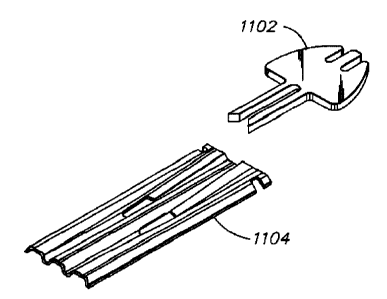
Figure 11 illustrates a preferred embodiment of isolation element 1008 that is
comprised of a molded bar 1102 and a formed foil management bar 1104. The
molded bar
can be an injection molded plastic bar that is fitted onto 804 and extends
into the 4 pair cable
(not shown).
The present invention has now been described in connection with a number of
specific
3o embodiments thereof. However, numerous modifications which are contemplated
as falling
with in the scope of the present invention should now be apparent to those
skilled in the art.
CA 02277524 1999-07-13
-15-
Therefore, it is intended that the scope of the present invention be limited
only by the scope of
the claims appended hereto.