Note: Descriptions are shown in the official language in which they were submitted.
CA 02277532 1999-07-16
REMOTE CONTROL LEARNING SYSTEM AND METHOD USING
S1GNAL ENVELOPE PATTERN RECOGNITION
BACKGROUND OF THE INVENTION:
Most manufacturers of televisions (TVs), video cassette recorders (VCRs) and
other
consumer electronic equipment provide remote control devices to control their
equipment.
Equipment of different manufacturers are usually controllccl with different
remote control devices.
To minimize the number of individual remote control devices a given user
requires, universal
remote control devices have been developed which must lie set-up to control
various functions of
a user's television, VCR, and other electronic equipment. A first method of
setting up a universal
remote control device requires the user to enter codes into the remote device
that correspoml and
conform to the makes and models of the various equipment to be controlled.
This type of nual~od
is commonly utilized in conjunction with so-called preprogrammed universal
remote controls. In
I S a second method of setting up a universal remote control device, codes
that are to be learned by
the remote control device are communicated to the remote control device from
the equipment or
unit to be controlled. Detailed descriptions of universal remote control
systems utilizing such set-
up methods can be found in U.S. Patent No. 5,255,313 issued to Paul V. Darbee
and in U.S.
Patent No. 4,626,848 issued to Ehlers.
The processes and algorithms used for teaching remote control devices to
control these
functions are well known in the art. Hence, the learning and teaching process
utilized by a
learning type universal remote control will be discussed I~erein only to the
extent necessary lu~r the
understanding of the invention.
377331.1
CA 02277532 1999-07-16
-S SUMMARY OF THE INVENTION:
The subject invention utilizes receiver signal reconstruction characteristics,
in combination
with a knowledge of the code formats being used, to enable a remote control
device to le..~rn the
coding format of devices operating at high carrier frequencies even though the
carrier frequencies
cannot be directly measured.
The foregoing features and advantages of the present invention will be
apparent from the
following more particular description of the invention. The accompanying
drawings, listed
hereinbclow, are useful in explaining the invention.
BRIEF DESCRIPTION OF DRAWINGS:
Fig. I is block diagram depicting a remote control device communicating with a
television;
1 S Fig. 2 shows wave forms of a typical IR signal transmitted from a device
to be controlled,
such as a television, to a remote control device;
Fig. 3 shows wave forms of a high frequency carrier signal transmitted such as
from a
television to a standard receiver in a remote control device;
Fig. 4 shows wave forms of a high frequency carrier signal transmitted such as
From a
television and reconstructed by a high frequency receiver in a remote control
device;
Fig. 5 shows a signal encoding scheme in accordance with the invention;
Fig. 6 shows the data frame of Fig. 5 when decoded from a high frequency
transmitter;
and,
Fig. 7 shows a tlow chart of the inventive method.
377331.1 2
CA 02277532 1999-07-16
DESCRIPTION OF TIDE INVENT10N:
Referring now to Figs. 1-4, a brief description of the drawing figures is
included
hereinbelow. As depicted in the block diagram of the inventive system 11 shown
in lvig. I , the
signal or code to be learned is transmitted, as indicated by dotted lines 14,
from a particular
remote control unit 12 of the electronic device to be controlled (TV, VCR or
other equipnncot) to
an infrared (IR) detector IS in the remote control device 16 which device has
to "learn" tl~e lsroper
codes to control that particular equipment. The IR to be learned is
transmitted to the detector,
amplified and applied to an input of a microcontroller (microprocessor) 17 in
the remote control
device 16. AS ShOWn l(l Fig. 2, since the response time of the electrical
circuitry in remote control
device 16 is limited, the originally transmitted signal shown as a square wave
in Fig. 2A is
actually presented at the microcontroller input 17 as shown in Fig. 2B; that
is, the signal is
distorted and is not an exact replica of the original signal.
The waveform of the transmitted signal as shown in Fig. 2A is typical. As tl~e
voltage
level applied to the microcontroller input shifts up and down, the logic value
of this iy~ut as
measured by the software in the microcontroller 17 will shin back and forth
between a one ( 1 ) and
a zero (0). This shift is determined by the range about a threshold level, as
indicted in I-~if~. 2B.
The precise value of the range and threshold level, which may also include
hysteresis, is a
characteristic of the particular microcontroller being used. At the sampling
points, indicated as
Fig. 2C, the binary state (1 or 0) of the input is sampled and stored. 'This
stored data can then be
used to replicate the sampled signal as shown in Fig. 2D.
The software program in the microcontroller 17 can monitor the logic state of
this input
either by repetitive sampling, or by using a suitable microcontroller hardware
interrupt feature to
377331.1
CA 02277532 1999-07-16
recognize each time the input changes state. For simplicity, only the
repetitive sampling neahod
is described herein; however, the interrupt method offers similar results, and
may be used
interchangeably for the purposes described.
The signal (Fig. 2A) is transmitted as burst of a carrier square (rectangular)
pulses, the
corresponding signal received by the microprocessor input is distorted as
shown in Fig. '?13, the
reconstructed signal as seen by the microcontroller 17 program is shown in
Fig. 2D, and the
resulting binary data is indicated at Fig. 2C. Thus, even though some delay
and/or distortion of
the original signal is introduced in the process, the "learning" software
algorithm is still able to
accurately ascertain the frequency of the original signal by counting the
number of binary
transitions (shifts) per unit time. The carrier frequency information,
together with the duration
of each burst and of the gaps between them then is used to form the definition
of the code to be
learned.
'hhe majority of infrared remote control code formats use carrier frequencies
Llnder
100KHz, well within the capabilities of inexpensive 1R receiver hardware and
standard--speed
microcontrollers to process the signal in the manner described above. However,
there are a
number of codes which use carrier frequencies above this range, as high as
400KHz to 1 Mlvz.
These codes using the higher carrier frequencies cause a problem to a
"learner" remote control
device 16 for two reasons.
First, the inexpensive receiver circuitry contained in the remote control
device l(i which
is suitable for use at the lower carrier frequencies does not usually have a
rapid enough resluonse
time to accurately track these higher frequency signals. 'This is because the
high frequency signal
ShOWII 111 Fig. 3A changes state faster than the receiver circuit can follow.
'The resultant signal
377331.1 4
CA 02277532 1999-07-16
at the microcontroller l7 input is shown in Fig. 3I3, and this signal may
never swing down from
the high level of the threshold. ~rhe sottware will detect no binary
transition and will deduce that
the input is a baseband as shown in Fig. 3D; that is, there is no carrier
burst. The result will be
no binary transitions and no coding, this is indicated in Fig. 3C.
Secondly, even if the remote control device l7 is equipped with a high
pertormance
receiver circuit, the microcontroller 17 itself may not be able to process the
input transitions
rapidly enough to obtain an accurate count. This is illustrated in Figure 4.
In this case, even
though the high frequency input signal transmitted as shown in Fig. 4A is
faithfully reproduced
at the micrcx:ontroller input, see Fig. 4I3, the microcontroller 17 program is
unable to process the
incoming pulse stream rapidly enough. Accordingly, some of the binary
transitions will be
missed. This results in an apparent input as shown in Fig. 4D. Obviously, this
will in turn cause
an incorrect binary count, as indicated in Fig. 4C. A result will be the
storage of an incorrect
carrier frequency (too low) in the learned code definition.
For the foregoing two reasons, most learning remote control devices are not
capable of
operating or controlling high frequency devices or equipment.
As alluded to above, the present invention relates to a method of enabling a
remote control
device to "learn" the coding format of devices operating at high carrier
frequencies even though
the carrier frequencies cannot be directly processed or measured by the remote
control device.
In many IR tCVIISIIIISSl011 sChe111eS the command to be sent is encoded as a
train of IR
carrier bursts and gaps wherein the variation in burst and/or gap duration is
used to represent a
string of binary values. These "frames" or groups of data are typically sent
repetitively for as long
as a key on the remote control is held down. Figure 5, shows one such scheme
wherein eight (8)
377331.1
CA 02277532 1999-07-16
S bits of data are encoded into an IR signaling frame. Fig. SA depicts several
frames of data. Fig.
SI3 shows a relatively enlarged single frame of Fig. SA. Fig. SC shows one
burst of tl~e carrier
signal. The frame of Fig. SQ comprises a series of fixed length IR bursts P1
with variable gap
duration GI and G2 between them, which is usually called Pulse Position
Modulation, or I'I'M.
Refer now to Fig. 6 which shows that each "pulse" consists of a burst of 1R
carrier signal.
In this particular scheme, the information content is encoded in the different
length of the gaps GI
and G2 between bursts, so it can be seen that the command shown in the example
is an eiglot (8)
bit value determined by G 1 and G2. If the value "0" is assigned to G 1 and
the value " 1 " is
assigned to G2, this corresponds to the byte value 01 lOlOlO, or "6A" in
hexadecimal code.
Many other types of pulse based encoding schemes exist, some using variations
of PPM
1 S encoding, others using schemes in which the burst length is the variable
known as Pulse Width
Modulation, or PWM. In still other schemes, both parameters are variable. 1-
Iowever, in every
case the data content of the frame is ultimately represented by a series of
burst widths and gap
widths.
In order to reproduce this command, a "learning" remote control thus needs to
memorize
and store:
a) the carrier frequency of the pulses to be sent; and
b) the series of burst times, gap times and positions to be used to replicate
the pulse
train corresponding to one frame of IR data.
In normal operation, with a teaching source using the usual carrier
frequencies, the
2S learning software measures the carrier frequency of each burst, as
described in conjunction with
Fig. 2 above, and stores this data together with the burst and gap t11111I1g
information. however,
377331.1 6
CA 02277532 1999-07-16
when the teaching source is a high frequency device and the learning unit has
a receiver
characteristic similar to that described above, the learning unit "sees" only
the burst./gap envelope
of the IR frame, and not the carrier itself.
Fig. 6 illustrates how the signal of the example from Fig. S would appear if
it were using
a high frequency carrier and is decoded by the inventive system. It has been
found that the
envelope contains information to allow determination of the burst and gap
timings even tltouglt the
carrier frequency remains unknown. Moreover, since the number of different
high frequency
encoding schemes which a particular learning remote control may be expected to
encounter is not
large, it is possible to identity these encoding schemes, or at least the most
popular of such
schemes, by matching characteristic information of the received envelope
pattern against the
known characteristics of these various high frequency encoding schemes. If a
match of
characteristic information is found, the carrier frequency to be used when the
microcontroller of
the remote control device regenerates the signal, can be inferred or deduced.
This takes advantage
of the characteristics discussed in conjunction with Fig. 3A above. An example
of the
characteristic information which might be searched against is shown in Table 1
which follows:
'TA13LI:
1
Number of Burst Burst Gap Gap C<~rrier
Bursts Per Duration Duration Duration Duration Freduency
Frame # 1 #2 # 1 #2
12 45 none 8600 5700 400KIIz
22 220 none 6000 3000 454KIIr
17 600 1200 600 none 330K I
l z
33 500 none 500 1500 1200K I
Iz
377331.1 7
CA 02277532 1999-07-16
For example, the entry in a table for the code pattern shown in Figure 6 would
be shown
in Table 2 as follows:
'FABLE
2
Number Burst Burst Gap Gap Carrier
of
Bursts Duration Duration Duration Duration Frccluenc:y
Per
Frame # I #2 # l #2
9 P1 none G1 G2 xxxKllz
Although the Tables l and 2 provide for five characteristic values, that is
bursts per Frame
plus two possibilities, each for burst and gap width, it should be understood
that in practice the
actual number of parameters used may be adjusted upwards or downwards as
necessary to
uniquely identify each high frequency code in the set to be supported. In
fact, certain parameter
types, for example the number of bursts per frame, may be omitted entirely if
the remaining items
are sufticient to uniquely identity all high frequency codes of interest in a
particular applicWion.
Also, in some cases, particular burst/gap combinations may occur only in
pairs. In the event that
all codes of interest exhibit a certain characteristic, these values may be
combined in the table and
treated as a single entity for the purpose of comparison. This approach is
illustrated in 'table 3
below:
TABLE 3
Number of Burst/Gap Burst/Gap Burst/Gap Carrier
Bursts Per Pair # I Pair #2 Pair #3 Frequency
Frame
12 45/8600 45/5700 none 400K11z
22 220/6000 220/3000 none 440KIrz
17 600/600 1200/600 2400/600 300KIIz
33 500/500 500/ 1500 9000/4500 1200K I Iz
377331.1
CA 02277532 1999-07-16
S Since there are codes in existence which use no carrier at all, "bascband"
codes, the
algorithm performing the search must default to "no carrier" in the event an
appropriate mulch is
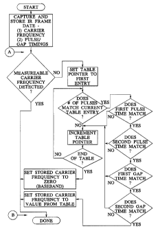
not bound. ~fl~e ilowclrart in (rigurc 7 shows laow such an envelope pattern
recognition loroccss is
implemented to support learning of one of a set of high frequency codes, when
using the set of
example characteristics shown in Table I above.
Referring to Figure 7, the software routine commences by receiving and
capturing tl~e IR
signal to be learned, using known techniques. The microc;ontroller stores the
values obtained from
the carrier frequency and burst/gap durations, which as described earlier are
sufficient to fully
define the signal to be learned. The microcontroller then checks the status of
the carrier
information to determine if a measurable carrier frequency value has been
detected. If a carrrier
frequency has been detected, the capture process is complete and no further
processing is needed.
However, if no carrier frequency is detected, the program then proceeds to
match the values
obtained for burst/gap durations against the entries in the table. The program
thus matches the
input parameters with a particular entry in the stored look-up tables and
determines the carrier
frequency of the input signal. In performing these comparisons, the program
allows a weable
range or tolerance around the exact table values, typically a tolerance of t %
to 5 % , to allow for
variations in the capture process.
Thus, if the program finds an entry for which values match within the given
tolerance, the
program determines that the newly stored carrier frequency is a frequency
contained in the table
entry. The newly stored carrier frequency is then updated or modified to the
frequency of the
table entry. If the program finds no match at all, the program assumes that
the captured values
correspond to a true baseband code and exits with the stored data unchanged.
377331.1
CA 02277532 1999-07-16
The characteristic information is thus effectively used to identify the
particular equipment
to be controlled, and to thereby to infer the carrier frequency to operably
control the equipment.
In an alternative embodiment of the invention, the processing steps between
points A and
B in Fig. 6 can be performed at the time the parameters are retrieved from
storage to regenerate
the signal for transmission, rather than at the time they were originally
stored. This technique has
the added advantage that it can be applied to data which was previously
captured by other devices
which did not include this algorithm, or were not equipped with suitable table
values.
A further modification of the system comprises a learning remote control
device in which
the table data for identifying high frequency devices is contained in the
read/write memory of the
microcontroller 17 and this can be updated to extend the range of high
frequency the system can
learn to control.
While the invention has been particularly shown and described with reference
to a
particular embodiment thereof it will be understood by those skilled in the
art that various changes
in forth and detail may be made therein without departing from the spirit and
scope of the
invention.
377331.1