Note: Descriptions are shown in the official language in which they were submitted.
CA 02277837 1999-06-11
WO 98/26282 PCT/US97/229I7
-1- _
ELECTROMAGNETIC FIELD PERTURBATION SENSOR AND METHODS
FOR MEASURING WATER CONTENT IN SHEETMAKING SYSTEMS
BACKGROUND OF THE INVENTION
Field of the Invention:
The present invention generally relates to systems for controlling continuous
sheetmaking systems and, more specifically, to sensors and methods for
measuring the
fiber weight of wetstock in a paper making machine.
I0
State of the Art:
In the art of modern high-speed papermaking, it is well known to continuously
measure certain properties of the paper material in order to monitor the
quality of the
finished product. These on-line measurements often include basis weight,
moisture
content, and sheet caliper (i.e., thickness). The measurements can be used for
controlling process variables with the goal of maintaining output quality and
minimizing the quantity of product that must be rejected due to upsets in the
manufacturing process.
The on-line sheet property measurements are often accomplished by scanning
sensors that periodically traverse the sheet material from edge to edge. For
example,
a high-speed scanning sensor may complete a scan in a period as short as
twenty
seconds, with measurements being read from the sensor at about 50 milliseconds
intervals. It is also know that a series of stationary sensors can be used to
make
similar on-line measurements.
In the manufacture of paper on continuous papermaking machines, a web of
paper is formed from an aqueous suspension of fibers (stock) on a traveling
mesh
papermaking fabric and water drains by gravity and suction through the fabric.
The
web is then transferred to the pressing section where more water is removed by
pressure and vacuum. The web next enters the dryer section where steam heated
dryers and hot air completes the drying process. The paper machine is, in
essence, a
water removal, system. A typical forming section of a papermaking machine
includes
an endless traveling papermaking fabric or wire which travels over a series of
water
CA 02277837 2004-10-07
2
removal elements such as table rolls, foils, vacuum foils, and suction boxes.
The. stock is carried on
the top surface of the papeimaking fabric and is de-watered as the stock
travels over the successive
de-watering elements to form a sheet of paper. Finally, the wet sheet is
transferred to the press
section of the papermaking machine where enough water is removed to form a
sheet of paper.
Papermaking devices well known in the art are described for example in U.S.
Pat. No.
5,400,258. Many factors influence the rate at which water is removed which
ultimately affects
the quality of the paper produced. As is apparent, it would be advantageous to
monitor the dynamic
process so as to, among other things, predict and control the dry stock weight
of l:he
paper that is produced.
It is conventional to measure the moisture content of sheet material upon its
leaving the
main dryer section or at the take up reel employing scanning sensors. Such
measurement may be used
to adjust the machine operation toward achieving desired parameters. One
technique for measuring
moisture content is to utilize the absorption spectrum of water in the infra-
red.
Monitoring or gauge apparatus for this purpose is commonly in use. Such
apparatus conventionally
uses either a tixed gauge or a gauge mounted on a scanning head which is
repetitively scanned transversely across the web at the exit from the dryer
section and/or upon
entry to the take up reel, as required by the individual machines. The gauges
typically use a
broad-band infra-red source and one or more detectors with the wavelength of
interest being
selected by a narrow-band filter, for example, an interference type filter.
The gauges used fall
into two main types: the transmissive type in which the source and detector
are on opposite sides of
the web and, in a scanning gauge, are scanned in synchronism across it, and
the scatter type
(sometimes called "retlective" type) in which the source and detector are in a
single head on one side
of the web, the detector responding to the amount of source radiation
scattered from the web.
SUMMARY OF THE INVENTION
The present invention is a sensor which is sensitive to three properties of
materials: the
conductivity or resistance, ~.e. resistive impedance) the dielectric constant,
and the proximity of the
CA 02277837 2004-10-07
material to the sensor. Depending on the material, one or more of these
properties will dominate.
The basic embodiment of the sensor of the present invention includes a fixed
impedance
element coupled in series with a variable impedance block between an input
signal and ground. The
fixed impedance element and the variable impedance block form a voltage
divider network such that
changes in impedance of the variable impedance block results in changes in
voltage on the output of
the sensor. The variable impedance block represents the impedance of the
physical configuration of at
least two electrodes within the sensor of the present invention and the
material residing between and
in close proximity to the electrodes. The impedance relates to the property of
the material being
measured.
The configuration of the electrodes and the material form an equivalent
circuit which can be
represented by a capacitor and resistor in parallel. The material capacitance
depends on the geometry
of the electrodes, the dielectric constant of the material, and its proximity
to the sensor. For a pure
dielectric material, the resistance of the material is infinite between the
electrodes and the sensor
measures the dielectric constant of the material. Alternatively, for a highly
conductive material, the
resistance of the material is much less than the capacitive impedance, and the
sensor measures the
conductivity of the material.
In one embodiment, the sensor is used to measure the conductivity i.e.
resistive impedance)
of an aqueous mixture (referred to as wetstock) in a papermaking system. In
this case, the
conductivity of the wetstock is high and dominates the measurement of the
sensor. The proximity is
held constant by contacting the support web in the papermaking system under
the wet stock. The
conductivity of the wetstock is directly proportional to the total water
weight within the wetstock,
consequently providing information which can be used to monitor and control
the quality of the paper
sheet produced by the papermaking system. In order to use the present
invention to determine the
weight of fiber in a wetstock mixture by measuring its conductivity, the
wetstock must be in a state
such that all or most of the water is held by the fiber. In this state, the
water weight of the wetstock
relates directly to the fiber weight and the conductivity
CA 02277837 1999-06-11
WO 98126282 PCT/US97/22917
of the water weight can be measured and used to determine the weight of the
fiber in
the wetstock.
In another embodiment, the sensor is used to measure the weight of plastic. In
this application the conductivity is negligible and the capacitive impedance
is inversely
proportional to the dielectric constant and the amount of plastic between the
electrodes
of the sensor.
In still another embodiment, the fixed impedance element is embodied as an
inductor and the input signal is an analog signal. In this embodiment, the
impedance
of the inductor can be selected to be a particular magnitude by setting the
frequency
of the input signal. The advantage of this embodiment is that for optimum
sensor
sensitivity the impedance of the fixed impedance element can be set to the
same range
as the impedance of the sensor. Hence, in the case in which the impedance of
the
sensor varies due to fluctuations in operating conditions of the system or the
material
being sensed, the impedance of the inductor can be customized to match the
sensor
impedance without any hardware changes.
The sensor apparatus of the present invention includes a sensor having a cell
array including two elongated grounded side electrodes and a center elongated
electrode spaced-apart and centered between the side electrodes. The center
electrode
is made-up of a string of sub-electrodes. A cell within the array is defined
as
including one of the sub-electrodes and the portions of the side electrodes
situated
adjacent to the center sub-electrode. The sub-electrode of each cell is
independently
coupled to an input signal provided by a signal generator through an impedance
element. In one embodiment, resistive elements are used for each impedance
element. Each cell forms a voltage divider network made-up of the resistive
element
coupled between the signal generator and the center sub-electrode of a given
cell and
of a resistance resulting from the effective water resistance between the
center
electrode and each of the portions of the side electrodes adjacent to the
center
electrode for the given cell. The output of each cell is taken from the center
electrode, i.e. the point between the resistive element and the cell. As the
conductance of the aqueous mixture changes so does the output voltage of the
cell.
The output voltage of each cell is coupled to a detector which, in one
embodiment,
1
CA 02277837 1999-06-11
WO 98/26282 PCT/US97/22917
includes circuitry for enhancing the signal such as an amplifier for
amplifying the
output signal from each cell and a rectifier. In one embodiment of the present
invention the detector includes circuitry for converting the output voltages
from each
cell into data relating to the weight of the aqueous mixture or to other
aqueous
mixture characteristics.
The apparatus of the present invention may optionally include a feedback
circuit which is used to adjust the input signal provided from the signal
generator to
compensate for changes in properties of the aqueous mixture that is not being
sensed,
but that also may affect the output voltages of the cells. The feedback
circuit includes
a reference cell having three electrodes in a similar configuration as a
single cell
within the cell array. The reference cell also has a center electrode coupled
to the
signal generator through a resistive element and is placed in recycled aqueous
mixture
from the cell array and consequently the reference cell is immersed in an
aqueous
mixture having essentially the same chemical and temperature properties as the
aqueous mixture that the cell array is in. Furthermore, the characteristic
that is being
measured (e.g. weight changes) is held constant on the reference cell while
all other
characteristics which may affect the output voltage from the reference cell
are allowed
to fluctuate. As a result, all voltage changes from the reference cell are due
to
property changes of the aqueous mixture (e.g. temperature, chemical
composition)
other than the characteristic that is being measured (e.g. weight changes).
The
voltage from the reference cell is then converted into a feedback signal and
then used
to adjust the signal from the generator to compensate for changes in aqueous
mixture
conductivity other than changes in weight.
In another embodiment, the array is configured so as to have two elongated
electrodes; a first grounded electrode and a second partitioned electrode made-
up of
sub-electrodes. A single cell includes one of the sub-electrodes and the
portion of the
grounded electrode adjacent to the sub-electrode. As with the previous
embodiment,
each sub-electrode is independently coupled to the signal generator through
one of a
plurality of impedance elements and the voltage changes are detected on the
sub-
electrode.
CA 02277837 1999-06-11
WO 98/26282 PCT/US9~122917
_ _
A third embodiment of the cell array is for detecting changes in dielectric of
the material between the electrode. This cell array includes first and second
partitioned elongated electrodes each made up of a set of first and second sub-
electrodes, respectively. A single cell includes adjacent spaced-apart pairs
of first and
second sub-electrodes. The first sub-electrode in a given cell is
independently coupled
to the signal generator through an impedance element and the voltage changes
are
detected on the second sub-electrode in the given cell are due to changes in
the
dielectric constant of the material are directly proportional to the weight of
the
material between the first and second sub-electrodes.
In one embodiment of the present invention, the apparatus is used in a
sheetmaking system which includes a web. The sensor is positioned under the
web
such that it is either parallel to the cross-direction or machine direction of
the
sheetmaking system and is in contact with the wetstock.
BRIEF DESCRIPTION OF THE DRAWINGS
Figure 1 A shows a basic block diagram of the apparatus of the present
invention and 1B shows that equivalent circuit of the sensor block.
Figure 2 shows a prior art sheetmaking system including the sensor of the
present invention in accordance with one implementation of the sensor of the
present
invention.
Figure 3 shows a block diagram of the sensor of the present invention
including the basic elements of the sensor.
Figure 4A shows an electrical representation of an embodiment of the sensor
of the present invention.
Figure 4B shows a cross-sectional view of a cell used within the sensor of the
present invention and its general physical position within a sheetmaking
system in
accordance with one implementation of the sensor of the present invention.
Figure SA shows a second embodiment of the cell array used in the sensor of
the present invention.
Figure 5B shows the configuration of a single cell in the second embodiment
of the cell array shown in Figure SA.
CA 02277837 1999-06-11
WO 98/26282 PCT/US97/22917
Figure 6A shows a third embodiment of the cell array used in the sensor of the
present invention.
Figure 6B shows the configuration of a single cell in the third embodiment of
the cell array shown in Figure 6A.
Figure 7 shows a basic block diagram of another embodiment of the present
invention.
DESCRIPTION OF THE PREFERRED EMBODIMENTS
The present invention relates to a sensor apparatus for detecting properties
of
material and, in one embodiment, for determining the weight of fiber in
wetstock in a
sheet making system. In its broadest sense, the sensor can be represented as a
block
diagram as shown in Figure 1A, which includes a fixed impedance element
(Zfixed)
coupled in series with a variable impedance block (Zsensor) between an input
signal
(Vin) and ground. The fixed impedance element may be embodied as a resistor,
an
inductor, a capacitor, or a combination of these elements. The fixed impedance
element and the impedance of Zsensor form a voltage divider network such that
changes in impedance of Zsensor results in changes in voltage on Vout. The
impedance block Zsensor shown in Figure 1A is representative of two electrodes
and
the material residing between the electrodes. The impedance block, Zsensor,
can also
be represented by the equivalent circuit shown in Figure 1B, where Rm is the
resistance of the material between the electrodes and Cm is the capacitance of
the
material between the electrodes.
The above-described sensor is sensitive to three physical properties of the
material being detected: the conductivity or resistance, the dielectric
constant, and the
proximity of the material to the sensor. Depending on the material, one or
more of
these properties will dominate. The material capacitance depends on the
geometry of
the electrodes, the dielectric constant of the material, and its proximity to
the sensor.
For a pure dielectric material, the resistance of the material is infinite
(i.e. Rm = oo)
between the electrodes and the sensor measures the dielectric constant of the
material.
Alternatively, for a highly conductive material, the resistance of the
material is much
CA 02277837 1999-06-11
WO 98/26282 PCT/US97/22917
-8- _
less than the capacitive impedance (i.e. Rm « Z~m), and the sensor measures
the
conductivity of the material.
To implement the above-described sensor, a signal Vin is coupled to the
voltage divider network shown in Figure 1A and changes in the variable
impedance
S block (Zsensor) is measured on Vout. In this configuration the sensor
impedance,
Zsensor, is:
Eq. 1 Zsensor = Zfixed*Vout/(Vin - Vout).
The changes in impedance of Zsensor relates physical characteristics of the
material
such as material weight, temperature, and chemical composition. It should be
noted
that optimal sensor sensitivity is obtained when Zsensor is approximately the
same as
or in the range of Zfixed.
In a physical implementation of the sensor shown in Figure 1A for performing
individual measurements of more than one area of a material, one electrode of
the
sensor is grounded and the other electrode is segmented so as to form an array
of
electrodes (described in detail below). In this implementation, a distinct
impedance
element is coupled between Vin and each of the electrode segments. In an
implementation for performing individual measurements of more than one area of
a
material of the sensor, the positions of the fixed impedance element and
Zsensor are
reversed from that shown in Figure 1A. In this implementation, one electrode
is
coupled to Vin and the other electrode is segmented and coupled to a set of
distinct
fixed impedances which, in turn, are each coupled to ground. Hence, neither of
the
electrodes are grounded in this implementation of the sensor.
In one particular embodiment, the above-described sensor is used for
measuring physical characteristics of an aqueous mixture (referred to as
wetstock) in a
sheetmaking system by detecting conductivity changes of the wetstock.
Figure 2 shows a typical sheetmaking system for producing a continuous sheet
of paper material 18 including a headbox 10, a steambox 20, a calendaring
stack 21, a
take-up reel 22 and sensor array 23. In the headbox 10, actuators are arranged
to
control discharge of wetstock onto supporting web 13. The sheet 18 is trained
to
CA 02277837 1999-06-11
WO 98/26282 PCT/US97/22917
travel between rollers 14 and 15 , and to pass through a calendaring stack 21.
The
calendaring stack 21 includes actuators 24 that control the compressive
pressure
applied across the paper web. The finished sheet product is collected on a
reel 22.
In practice, the portion of the paper making process near a headbox is
referred to as
S the "wet end" , while the portion of the process near a takeup reel is
referred to as the
"dry end".
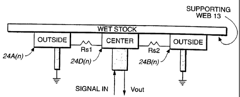
In one implementation, the sensor is mounted beneath supporting web 13 for
sensing certain properties of the wetstock on the web. Figure 3 illustrates a
block
diagram of one implementation of the sensor apparatus including cell array 24,
signal
generator 25, detector 26, and optional feedback circuit 27. Cell array 24 is
made-up
of two elongated grounded electrodes 24A and 24B and center electrode 24C
spaced
apart and centered between electrodes 24A and 24B and made-up of sub-
electrodes
24D(1) - 24D(n). A cell within array 24 is defined as including one of sub-
electrodes
24D situated between a portion of each of the grounded electrodes 24A and 24B.
For
example, cell 2 includes sub-electrode 24D(2) and grounded electrode portions
24A(2)
and 24B(2). For use in the system as shown in Figure 2, cell array 24 resides
beneath and in contact with supporting web 13 and can be positioned either
parallel to
the machine direction (MD) or to the cross-direction (CD) depending on the
type of
information that is desired. In order to use the sensor apparatus to determine
the
weight of fiber in a wetstock mixture by measuring its conductivity, the
wetstock must
be in a state such that all or most of the water is held by the fiber. In this
state, the
water weight of the wetstock relates directly to the fiber weight and the
conductivity
of the water weight can be measured and used to determine the weight of the
fiber in
the wetstock.
Each cell is independently coupled to an input voltage (Vin) from signal
generator 25 through an impedance element Zfixed and each provides an output
voltage to voltage detector 26 on bus Vout. Signal generator 25 provides Vin.
In one
embodiment Vin is an analog waveform signal, however other signal types may be
used such as a DC signal. In the embodiment in which signal generator 25
provides a
waveform signal it may be implemented in a variety of ways and typically
includes a
crystal oscillator for generating a sine wave signal and a phase lock loop for
signal
CA 02277837 1999-06-11
WO 98/26282 PCT/US97/22917
_ 10_ _
stability. One advantage to using an AC signal as opposed to a DC signal is
that it
may be AC coupled to eliminate DC off-set.
Detector 26 includes circuitry for detecting variations in voltage from each
of
the sub-electrodes 24D and any conversion circuitry for converting the voltage
variations into useful information relating to the physical characteristics of
the aqueous
mixture. Optional feedback circuit 27 includes a reference cell also having
three
electrodes similarly configured as a single cell within the sensor array. The
reference
cell functions to respond to unwanted physical characteristic changes in the
aqueous
mixture other than the physical characteristic of the aqueous mixture that is
desired to
be measured by the array. For instance, if the sensor is detecting voltage
changes due
to changes in weight, the reference cell is configured so that the weight
remains
constant. Consequently, any voltage/conductivity changes exhibited by the
reference
cell are due to aqueous mixture physical characteristics other than weight
changes
(such as temperature and chemical composition). The feedback circuit uses the
voltage changes generated by the reference cell to generate a feedback signal
(Vfeedback) to compensate and adjust Vin for these unwanted aqueous mixture
property changes (to be described in further detail below). The non-weight
related
aqueous mixture conductivity information provided by the reference cell may
also
provide useful data in the sheetmaking process.
Figure 4A shows an electrical representation of cell array 24 (including cells
1
- n) and the manner in which it functions to sense changes in conductivity of
the
aqueous mixture. As shown, each cell is coupled to Vin from signal generator
25
through an impedance element which, in this embodiment, is resistive element
Ro.
Referring to cell n, resistor Ro is coupled to the center sub-electrode
24D(n). The
outside electrode portions 24A(n) and 24B(n) are both coupled to ground. Also
shown in Figure 4A are resistors Rsl and Rs2 which represent the conductance
of the
aqueous mixture between each of the outside electrodes and the center
electrode. The
outside electrodes are designed to be essentially equidistant from the center
electrode
and consequently the conductance between each and the center electrode is
essentially
equal (Rsl =Rs2=Rs). As a result, Rsl and Rs2 form a parallel resistive branch
having an effective conductance of half of Rs (i.e. Rs/2}. It can also be seen
that
CA 02277837 1999-06-11
WO 98/26282 PCT/I1S97/22917
-11- -
resistors Ro, Rsl, and Rs2 form a voltage divider network between Vin and
ground.
Figure 4B also shows the cross-section of one implementation of a cell
electrode
configuration with respect to a sheetmaking system in which electrodes 24A(n),
24B(n), and 24D(n) reside directly under the web 13 immersed within the
aqueous
mixture.
The above-described sensor apparatus is based on the concept that the
conductivity Rs of the aqueous mixture and the weight /amount of an aqueous
mixture
are inversely proportional. Consequently, as the weight increases/ decreases,
Rs
decreases/increases. Changes in Rs cause corresponding fluctuations in the
voltage
Vout as dictated by the voltage divider network including Ro, Rsl, and Rs2.
The voltage Vout from each cell is coupled to detector 26. Hence, variations
in
voltage directly proportional to variations in conductivity of the aqueous
mixture are
detected by detector 26 thereby providing information relating to the weight
and
amount of aqueous mixture in the general proximity above each cell. Detector
26
may include means for amplifying the output signals from each cell and in the
case of
an analog signal will include a means for rectifying the signal to convert the
analog
signal into a DC signal. In one implementation well adapted for electrically
noisy
environments, the rectifier is a switched rectifier including a phase lock-
loop
controlled by Vin. As a result, the rectifier rejects any signal components
other than
those having the same frequency as the input signal and thus provides an
extremely
well filtered DC signal. Detector 26 also typically includes other circuitry
for
converting the output signals from the cell into information representing
particular
characteristics of the aqueous mixture.
Figure 4A also shows feedback circuit 27 including reference cell 28 and
feedback signal generator 29. The concept of the feedback circuit 27 is to
isolate a
reference cell such that it is affected by aqueous mixture physical
characteristic
changes other than the physical characteristic that is desired to be sensed by
the
system. For instance, if weight is desired to be sensed then the weight is
kept
constant so that any voltage changes generated by the reference cell are due
to
physical characteristics other than weight changes. In one embodiment,
reference cell
28 is immersed in an aqueous mixture of recycled water which has the same
chemical
CA 02277837 1999-06-11
WO 98126282 PCTIUS97/22917
-12-
and temperature characteristics of the water in which cell array 24 is
immersed in.
Hence, any chemical or temperature changes affecting conductivity experienced
by
array 24 is also sensed by reference cell 28. Furthermore, reference cell 28
is
configured such that the weight of the water is held constant. As a result
voltage
S changes Vout(ref. cell) generated by the reference cell 28 are due to
changes in the
conductivity of the aqueous mixture, not the weight. Feedback signal generator
29
converts the undesirable voltage changes produced from the reference cell into
a
feedback signal that either increases or decreases Vin and thereby cancels out
the
affect of erroneous voltage changes on the sensing system. For instance, if
the
conductivity of the aqueous mixture in the array increases due to a
temperature
increase, then Vout(ref. cell) will decrease causing a corresponding increase
in the
feedback signal. Increasing Vfeedback increases Vin which, in turn,
compensates for
the initial increase in conductivity of the aqueous mixture due to the
temperature
change. As a result, Vout from the cells only change when the weight of the
aqueous
mixture changes.
One reason that the cell array is configured as shown in Figure 3, with the
center electrode placed between two grounded electrodes, is to electrically
isolate the
center electrode and to prevent any outside interaction between the center
electrode
and other elements within the system. However, it should also be understood
that the
cell array can be configured with only two electrodes. Figure SA shows a
second
embodiment of the cell array for use in the sensor. In this embodiment, the
sensor
includes a first grounded elongated electrode 30 and a second partitioned
electrode 31
including sub-electrodes 32. A single cell is defined as including one of the
sub-
electrodes 32 and the portion of the grounded electrode 30 which is adjacent
to the
corresponding sub-electrode. Figure SA shows cells 1 - n each including a sub-
electrode 32 and an adjacent portion of electrode 30. Figure SB shows a single
cell n,
wherein the sub-electrode 32 is coupled to Vin from the signal generator 25
through a
fixed impedance element Zfixed and an output signal Vout is detected from the
sub-
electrode 32. It should be obvious to one skilled in the field of circuit
design that the
voltage detected from each cell is now dependent on the voltage divider
network, the
variable impedance provided from each cell and the fixed impedance element
coupled
CA 02277837 1999-06-11
WO 98/26282 PCT/US97/22917
-13- -
to each sub-electrode 32. Hence, changes in conductance of each cell is now
dependent on changes in conductance of Rs 1.' It should also be understood
that the
remainder of the sensor functions in the same manner as with the embodiment
shown
in Figure 4A. Specifically, the signal generator provides a signal to each
cell and
feedback circuit 27 compensates Vin for variations in conductance that are not
due to
the characteristic being measured.
It should be understood that the cells shown in Figures SA and SB may
alternatively be coupled such that Vin is coupled to electrode 30 and each of
suh-
electrodes 32 are coupled to fixed impedance elements which, in turn, are
coupled to
ground.
In still another embodiment of the cell array shown in Figures 6A and 6B, the
cell array includes first and second elongated spaced apart partitioned
electrodes 33
and 34, each including first and second sets of sub-electrodes 36 and 35,
(respectively). A single cell (Figure 6B) includes pairs of adjacent sub-
electrodes 35
and 36, wherein sub-electrode 35 in a given cell is independently coupled to
the signal
generator and sub-electrode 36 in the given cell provides Vout to a high
impedance
detector amplifier which provides Zfixed. This embodiment is useful when the
material residing between the electrodes functions as a dielectric making the
sensor
impedance high. Changes in voltage Vout is then dependent on the dielectric
constant
of the material. This embodiment is conducive to being implemented at the dry
end
(Figure 2) of a sheetmaking system (and particularly beneath and in contact
with
continuous sheet 18) since dry paper has high resistance and its dielectric
properties
are easier to measure.
In still anther embodiment, the fixed impedance element is embodied as an
inductor or capacitor and the input signal is an oscillating waveform as shown
in
Figure 7. The advantage of this embodiment is that the fixed impedance of the
inductor or capacitor can be set by adjusting the frequency of the input
signal
(Zinduccor = I- * 27f FV;n or Z~aP =1/(2~r Fv;~*C)). Furthermore, for the case
of
measuring conductivity, changing the frequency of the input signal does not
change
the impedance of the cell. By customizing the impedance of the inductor or
capacitor
to be close to or approximately equal to the impedance of the sensor, optimal
CA 02277837 1999-06-11
WO 98/26282 PCT/US97/22917
-14- -
sensitivity is obtained. In addition, this optimization can be obtained
without any
hardware changes.
The foregoing has described the principles, preferred embodiments and modes
of operation of the present invention. However, the invention should not be
construed
as limited to the particular embodiments discussed. Instead, the above-
described
embodiments should be regarded as illustrative rather than restrictive, and it
should be
appreciated that variations may be made in those embodiments by workers
skilled in
the art without departing from the scope of present invention as defined by
the
following claims.