Note: Descriptions are shown in the official language in which they were submitted.
CA 02277923 1999-07-14
WO 98/33008 PCT/US97/09135
OPTICAL FIBER ILLUMINATION SYSTEM
FIELD OF THE INVENTION
The present invention relates to illumination systems that employ optical
fibers
s as a light transpon:ing mechanism. In particular, the present invention
relates to
illumination systenns that employ light guides for transporting and
distributing light
energy.
BACKGROUND
It is known that optically transmissive materials such as glass or polymers
may
fo be used as a light I;uide to propagate light. A light guide typically
includes at least one
surface adapted to receive fight from a light source and an optically smooth
surface Ei~r
reflecting light propagating through the light guide. Common examples of light
guides
include optical fibers traditionally used in the data communications industry
and more
recently used for illumination purposes (See e.g. U.S. Pat. No. 5,432,876). At
least
15 one end surface of the optical fiber is adapted to receive light from a
light source which
propagates axially through the fiber. Planar waveguides used in the optical
display
industry are another example of optical waveguides. At least one end surface
of the
planar waveguide is adapted to receive light from a light source. Light
injected into
the waveguide propagates t>etween the two major surfaces of the waveguide.
2o It is also known that optical fiber may be used as a component of an
illumination system. Light may be injected into one end of an optical fiber
and allowed
to exit the fiber at si predetermined position along the fiber. Techniques for
encouraging light to exit the fiber include subjecting the fiber to relatively
sharp bends,
generally known as. microbends (U.S. Pat. Nos. 4,171,844; 4,885,663;
4,907,132;
25 German Patent No. 3801385) and removing and/or roughening a portion of the
optical
fiber core or cladding to provide a diffuse surface which allows light to
escape (French
Pat. No. 2626381; Japanese: Utility Model Registration Nos. 62-9205; 62-9206)
Each
of these techniques are essentially passive extraction techniques which allow
light to
leak from an optical fiber in an uncontrolled fashion.
30 U.S. Pat. No. 5,432,876 (the '876 Patent) is directed toward an optical
fiber
having a .plurality of reflecting surfaces formed in the core of the optical
fiber which
reflect, in a radial direction, a portion of the light propagating axially
through the fiber
CA 02277923 2004-09-22
WO 98!33008 PCT/US97/09135
WO 97/08490 dated 6 March 1997, is directed
toward an illumination system wherein a light extraction overlay having a
plurality of
reflecting surfaces is optically coupled with an optical fiber to extract
light from the
fiber. In contrast to previous passive light extraction techniques, these
systems
actively reflect light from the fiber.
In any given optical fiber illumination application it is desirable to control
at
least two variables. The first variable is the rate at which optical power is
extracted
from the optical fiber. In a system that utilizes reflective surfaces to
extract light from
the waveguide, the rate of optical power extraction per unit length of optical
fiber is a
function of the total cross-sectional area of optical element reflecting
surfaces per unit
length to the cross-sectional area of the fiber over the unit length. The
greater the total
cross-sectional area of reflecting surfaces in a given lengnh of optical
fiber, the greater the
rate of optical power extraction from the fiber, assuming a constant optical
fiber diameter
over the length. Increasing the depth to which optical elements extend into an
optical fiber
or decreasing the distance between adjacent elements results in an increased
rate of optical
power extraction from an optical fiber.
It is also desirable to control the directional distribution of light energy
extracted from an optical fiber. Light extracted from an optical fiber in
accordance
with the invention described in the '8?6 Patent exits the fiber with an
emerging angular
distribution. It is desirable to control the angular spread of light energy in
both the
longitudinal (e.g. down-fiber) direction and the lateral (e.g. cross-fiber)
direction. 'fhe
longitudinal (e.g. down-fiber) distribution of light energy in the emerbing
angular
distribution is primarily a function of the cone angle of light propagating
through the
optical fiber. The lateral (e.g. cross-fiber) distribution of light energy in
the emerging
angular distribution is primarily a function of the angle circumscribed by the
reflecting
surfaces of the optical elements. For optical elements having flat bases, the
angle
circumscribed by the reflecting surfaces of the optical elements is a function
of depth
the reflecting surface extends into the optical fiber core. Thus, increasing
the depth to
which an optical element extends into an optical fiber has the. corollary
effect of
3o increasing the lateral (e.g. cross-fiber) distribution of light energy in
the emerbing
angular distribution and thus the amount of optical power extracted from the
fiber by
the element.
CA 02277923 1999-07-14
WO 98/33008 PCT/US97/09135
The correlation between the lateral distribution of the divergence cone of
reflected light and the power of extracted light imposes limitations on the
design of
optical illumination systems. For example, in some applications it may be
desirable to
broaden the lateral distribution of light energy in the divergence cone of
light extracted
from the fiber without dramatically affecting the longitudinal distribution of
light
energy or the rate of power extraction from the fiber.
It is also dc;sirable to control the spatial intensity of light energy within
the
emerging angular distribution of light energy. In illumination systems that
include a
plurality of optical elements spaced closely adjacent one another along the
axis of
to propagation to reflect light from the waveguide each optical element blocks
a portion
of the light that would otherwise be incident on the subsequent element. ror
tlrc
purposes of this application, this phenomena shall be referred to as
'shadowing'.
Shadowing introduces variability into the spatial intensity of light energy in
the
emerging angular distribution of light reflected from a waveguide. In some
designs the
shadowing effect is sufficiently severe to generate dark spots, also called
voids or
holes, in the angular distribution of light energy reflected from a waveguide.
The
variability in the angular distribution of light energy introduced by
shadowing etFects is
generally considered undesirable. This variability is particularly undesirable
for
applications in which the waveguide is used as a light source for direct
viewing such
2o as, for example, as. a warning light on a motor vehicle.
Thus, there; is a need in the art for an optical waveguide in which the
lateral
distribution of light energy in the emerging angular distribution may be
controlled
independent of the longitudinal distribution of light energy, and thus the
rate of power
extraction. There is also a need in the art for an optical waveguide that
compensates
for shadowing effects caused by closely spaced optical elements.
SUMMARY OF THE INVENTION
The present invention addresses these and other issues by providing an
illumination systenn that includes an optical fiber having an optically smooth
surface for
3o propagating light through the fiber and a light emitting region that
extends along a
portion of the fiber. The light emitting region includes at least one, and
preferably a
plurality, of optical elements centered about a first longitudinal axis
extending along
CA 02277923 1999-07-14
WO 98/33008 PCT/US97I09135
4
the optically smooth surface of the optical fiber. The light emitting region
further
includes at least one, and preferably a plurality, of optical elements
centered about a
second longitudin~~l axis extending along the optically smooth surface of the
optical
fiber. The second longitudinal axis is angularly displaced from the first
longitudinal
axis.
In another embodirnent, the invention provides an optical waveguide adapted
to reduce visible variations the angular intensity of light reflected from the
waveguide
in a viewing region centered about an axis disposed at a desired viewing
angle, y. The
waveguide compriises a core formed from a substantially optically transparent
material
to having a first surface adapted for receiving light from a light source and
at least one
optically smooth surface far propagating light through the waveguide along an
axis of
propagation. The optical surface comprises a plurality of optical elements,
each optical
elements having a~: least one optically reflective surface disposed at an
oblique angle (~
to a plane perpendlicular to the axis of propagation; the angle 8 being
determined by
the equation:
90 + y'
+5
2
wherein i; is selected from the group of angles extending from (a/2) to ((1/2)
or (-(112)
to (-a) and wherein
a = the sh~idowing angle
~i = the cone angle of light propagating through the optical fiber; and
y' = the desired exit angle of reflected light.
BRIEF DESCRIPTION OF THE DRAWINGS
Fig. I is a cross-sectional view of an optical fiber illustrating the
propagation of
light through the fiber;
Fig. 2 is a perspective view of a segment of an optical fiber in accordance
with
aspects of the present invention; '
Fig. 3 is a plan view of the optical surface of the optical fiber depicted in
Fig. 2;
Fig. 4 is a .cross-sectional view, taken along a longitudinal axis, of a
portion of
3o an optical fiber depicted in Fig. 2;
CA 02277923 1999-07-14
WO 98/33008 PCT/US97/09135
Fig. 5 is a cross-sectional view, taken perpendicular to a longitudinal axis,
of a
portion of the optical fiber depicted in Fig. 2;
Fig. 6 is a schematic view of an optical fiber illumination system in
accordance
with aspects of the present invention;
' S Fig. 7 is a cross-sectional view of an optical fiber illustrating
shadowing effects
in the fiber;
Fig. 8 is a graphical depiction of the angular distribution of light rays
incident
on a portion of a reflective surface in the optical fiber depicted in Fig. 6;
Fig. 9 is a graphical depiction of the angular distribution of light rays,
similar to
to Fig. 8.
DETAILED DESCRIPTION
The present invention is directed toward providing light guides which are
capable
of emitting light and that find particular utility in the construction of
illumination systems. In
describing the invention, specific embodiments and terminology will be used
for the sake of
clarity. The invention, however, is not intended to be limited to the
specifically described
embodiments and terms. In particular, the present invention will be explained
with reference
to a optical fiber light guide: having that is generally circular in cross-
section. However, one
of ordinary skill in the art w711 recognize that principles of the present
invention apply
2o optical fibers of different cross-sectional shapes and to planar
waveguides.
By way ofbackground, referring to Fig. l, light injected into an optical fiber
10
propagates through fiber 10 along an axis of propagation 12 substantially
coincident with
the longitudinal axis of fiber 10. The light propagates through the fiber with
a maximum
cone angle, ~3, me;3sured from the axis of propagation 12 that is determined
by the critical
angle necessary for total internal reflection. The angle ~i may be derived by
first calculating
the critical angle (~Bc) reduired for total internal reflection from Snell's
law as follows:
~"~~ -
s»r a
",
3o where y is the re.~Fractive index of the optical fiber core material and
rlz is the refractive
index of the surrounding medium, typically a cladding material or air. The
cone angle ~ is
the complement of the critical angle A~. Thus, light propagates through
optical fiber I0 in a
CA 02277923 1999-07-14
WO 98/33008 PCT/US97/09135
G
cone angle ~i that i:~ proportional to the ratio of the retractive index of
the core material to
the refractive index: of the medium surrounding the core.
According to one aspect of the present invention an optical fiber is provided
with
reflective elements for extracting light from the fiber in a manner that
broadens the lateral
(e.g. crass-fiber) distribution of light energy extracted from the fiber
without substantially
affecting the longitiudinal (e.g. down-fiber) distribution of light energy
extracted from the
fiber. In a preferred embodiment there is provided an optical fiber including
an optical
fiber core having an optically smooth surface for propagating light through
the fiber
and a light emitting region along at least a portion of its lengrth, the light
emitting region
to preferably includes a plurality of optical elements centered about a first
longitudinal axis
extending along the optically smooth surface of the optical fiber core and a
plurality of
optical elements enntered about a second longitudinal axis along the optically
smooth
surface of the optical fiber core. Each optical element includes at least one
optically
reflective surface Extending into the optical fiber core such that a portion
of the light
striking the optical element is reflected out of the optical fiber.
A preferred embodiment of an optical waveguide according to the present
invention is set forth in Figs. 2-6. Fig. 2 is a perspective view of a portion
of an optical
fiber 20 in accordance with aspects of the present invention and Fig. 3 is a
plan view of
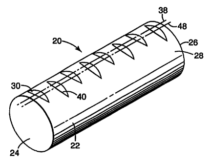
a portion thereof. Optical :fiber 20 includes an optical fiber core 22 having
a first end
2o surface 24, a second end surface 26, and an optically smooth surface 28
extending
longitudinally along the length of fiber 20. Preferably, optically smooth
surface 28
corresponds to the; circumferential surface of optical fiber core 22. As used
herein, the
term optically smooth surface shall refer to a surface that is capable of
reflecting light
incident on the surface with minimal scattering or diffusion such as is
possible when the
surface roughness is small i,n comparison to the wavelength of light. Although
the fiber
depicted in Fig. 2 :is a 'naked' fiber, it will be appreciated by one of
ordinary skill in ti-:
optical arts that the fiber may include a cladding layers) and/or additional
jacketing
layers.
Optical fiber 20 is provided with a plurality of optical elements 30 centered
3o about a first longitudinal axis 38 extending along the optically reflective
surface 28 of
optical fiber 20 arnd a plurality of optical elements 40 centered about a
second
longitudinal axis 48 of optical fiber 20. According to one aspect of the
present
CA 02277923 1999-07-14
WO 98/33008 PCT/US97/09135
invention, first longitudinal axis 38 is displaced from second longitudinal
axis 48. For
most optical fibers, it is convenient to measure the angular displacement 8
(Fig. S)
between first longitudinal .axis 38 and second longitudinal axis 48. However,
the
displacement between the two longitudinal axes may also be measured as a
distance
along the reflective surface 28 of optical fiber 20. A distance measurement
may be
appropriate for optical fibers having polygonal cross-sectional shapes.
Referring t:o Figs. 3 and 4, optical fiber 20 is provided with a plurality of
optical
elements 30 centered about a first longitudinal axis 38 along optically
reflective surface 28
of fiber 20. Preferably, each optical element 30 includes a first optically
reflective
to surface 32 that extends into the core 22 of optical fiber 20. Optically
reflective surface
32 is preferably a substantially optically smooth surface, meaning that it is
capable of
reflecting light with minimal losses due to scattering or diffusion. Surface
32 may be
disposed at any usefial angle between 0° and 90° from an axis
perpendicular to the axis
of propagation. F?ach optical element 30 also includes a second surface 34
which may
t5 or may not be optically reflective. Surfaces 32 and 34 intersect to define
the base 36 ~f
optical element 30. Optical fiber 20 is fiarthec provided with a plurality
ofoptical
elements 40 centered about a second longitudinal axis 48 along the optically
retlective
surface of fiber 20. Preferably, each optical element 40 includes a first
optically
reflective surface 42 that extends into the core 22 of optical fiber 20.
Optically
2o reflective surface 42 is also preferably a substantially optically smooth
surface, meaning
that it is capable of reflecting Light with minimal losses due to scattering
or diffusion.
Surface 42 maybE: disposed at any usefial angle between 0° and
90° from an axis
perpendicular to t:he axis of propagation. Each optical element 40 also
includes a
second surface 44 which may or may not be optically reflective. Surfaces 42
and 44
25 intersect to define the base 46 of optical element 40.
Referring to Figs. 4 and S, in use, a first portion of the light propagating
through
optical fiber core 22, represented by light ray 50 becomes incident on an
optically reflective
surface 32 of optical element 30 and is reflected through optical fiber 20
such that it strikes
the optically smooth surface 28 of optical fiber 20 at an angle greater than
the critical angle
3o required for continued propagation through the fiber and thus is at least
partially retracted
from optical fiber 2Ø A second portion of the light propagating through
optical fiber 1 U,
represented by light ray 58, strikes the optically reflective surface 28 of
optical fiber 1 U and
CA 02277923 1999-07-14
WO 98/33008 PCT/US97/09135
continues to propagate through optical fiber 10. And a third portion of the
tight
propagating through optical fiber core 22, represented by light ray 60 becomes
incident on
an optically reflective surface 42 of optical element 40 and is reflected
through oprical fiber
20 such that it strikes the optically smooth surface 28 of optical fiber 20 at
an angle less
than the critical angle required for continued propagation and thus is at
least partially
refracted from optical fiber 20.
Fig. 5 is a schematic, cross-sectional view, taken perpendicular to a
longitudinal
axis of optical fiber 20, that illustrates an aspect of the present invention.
Dashed line 36
represents the bottom edge of an optical element 30, disposed about first
longitudinal axis
io 38, while solid line 46 represents the bottom edge of an optical element
40, disposed about
second longitudinal axis 48. Axes 38 and 48 are angularly displaced by an
angle 8. Light
rays 52 and 54 represent the limiting light rays reflected from optical fiber
20 by an optical
element 30 disposed about first axis 38. Accordingly light reflected from
optical element
30 emerges in a profile that extends through the included angle defined by
light rays S2 and
i5 54. Similarly, light rays 62 and 64 represent the limiting light rays
reflected from optical
fiber 20 by an optical element 40 disposed about second axis 48. Accordingly
light reflected
from optical element 40 emerges in a profile that extends through the included
angle
defined by light rays 62 and 64.
As Fig. 5 illustrates, the net effect of disposing optical elements about two
distinct
20 longitudinal axes is to broaden the lateral (e.g. cross-fiber) distribution
of light ener~,ry in the
divergence profile of light reflected from optical fiber 20. Advantageously,
the lateral
distribution of light energy is broadened without significantly affecting the
divergence
profile in the longitudinal (e.g. down-fiber) direction. Thus, the lateral
distribution of light
energy in the divergence profile may be controlled without substantially
affecting of the
25 longitudinal distribution of light energy in the divergence profile by
disposing optical
elements about two or more distinct longitudinal axes along the surface of the
optical fiber.
This may be accornplished using optical elements that have substantially flat
(e.g.
linear) groove bases (e.g. 36, 46) and which are substantially identical in
size and
geometry. These 'factors facilitate the design and manufacture of optical
fiber
3o illumination systenns because the properties of'such optical elements are
easier to
model than the properties of more complex optical elements. Additionally,
optical
CA 02277923 1999-07-14
WO 98/33008 PCT/US97/09135
elements having flat (e.g. linear) groove bases are easier to manufacture than
optical
elements having a. more complex geometry.
It will be apparent to one of ordinary skill in the art that the minimum
angular
displacement 8 is slightly greater than 0°, in which case the axes are
nearly coincident,
and the maximum angular displacement 8 is 180°. 1n practice, the
displacement 8
between first longitudinal axis 20 and second longitudinal axis 22 is governed
primarily
by functional considerations. More particularly, the angular displacement 8 is
determined by the. desired angular spread of the divergence cone of reflected
light in
the lateral (e.g. cross-fiber) dimension and may be determined using optical
modeling
to techniques known to one of ordinary skill in the art. For many applications
where the
optical fiber is used to illuminate a broad area, angular displacements of up
to ! 00° are
useful to spread the emerging light into a broad angular distribution. By
contrast, in
applications where the optical fiber is viewed directly such as, for example,
a vehicle
warning light, it may be desirable to narrow the lateral dimension of the
angular
distribution of emerging light to concentrate the light within a desired
angular range.
For such applications, angular displacements 8 between about S° and
20° are useii.rl.
Another bE:nefit associated with disposing optical elements about distinct
longitudinal axes extending along the surface of optical fiber 20 relates to
shadowing ellccts
in the fiber. Shadowing effects are discussed at length below. In brief, each
optical element
2o in an optical fiber shadows t:he adjacent optical element from a portion of
the light rays
propagating throus,;h optical fiber 20. The degree of shadowing is
proportional to the depth
to which the optical element extends into the optical fiber 20. Providing
optical elements
disposed about two distinct longitudinal axes on the surface of optical fiber
20 in
accordance with the present: invention reduces detrimental effects associated
with
shadowing by allo~Ning Light: to be spread into a broader divergence cone
without resorting
to deeper optical elements as required in single axis embodiments.
Additionally, because
the optical elementa are displaced from one another, shadowing effects are
spread more
evenly around the perimeter of optical fiber 20, making their effects less
noticeable.
One of orclinary skill in the optical arts will appreciate that benefits of
the present
3o invention may be obtained with optical elements disposed about more than
two longitudinal
axes extending along the surface of optical fiber 20. For example, an optical
fiber
illumination system may incorporate optical elements disposed about three or
more distinct
CA 02277923 1999-07-14
WO 98/33008 PCT/US97/09135
longitudinal axes extending along the surface of optical fiber 20. The
displacement between
longitudinal axes nnay be predetermined to achieve a specific optical
objective or,
alternatively, may lbe random.
Reflective surfaces :32, 42 of optical elements 30, 40 respectively may be
coated
5 with a specularly reflective substance (e.g. silver, aluminum) such that
light striking these
surfaces is specularly reflected. However, if reflective surfaces 32, 42 are
not coated with a
specularly reflective substance, light incident on the reflective surface at
an angle less than
the critical angle defined by Snell's law will be transmitted ( and refracted)
through the
optical element. H~y contrast, light incident on the reflective surface at an
angle greater than
l0 the critical angle defined by Snell's law will be totally internally
retlected, much like the light
depicted by rays 30.
As discussed above., light extracted from an optical fiber by optical elements
exits
the fiber with an emerging angular distribution. The longitudinal (e.g. down-
fiber)
distribution of light energy in the divergence cone is primarily a fi.tnction
of the cone
t5 angle of light propagating through the optical fiber. This distribution may
be adjusted
providing the reflective faces of optical elements I 0 with optical power,
such as by
introducing a curvature into these surfaces. Alternatively, the longitudinal
distribution
of light energy may be adjusted by altering the cone angle of ligln
propagating through
optical fiber 20. The lateral (e.g. cross-fiber) distribution of light energy
in the
2o divergence cone is a function of the depth to which the optical element
reflecting
surfaces extend into optical fiber 20. Thus, increasing the depth to which an
optical
element extends into optical fiber core increases the angular spread of light
energy in
the divergence cone.
Optical fit>er 20 is preferably formed from a substantially optically
transmissive
25 material. Preferred materials exhibit high optical transmission and have
relatively high
refractive indices. Common materials include poiymethyimethacrylate
(refractive index
1.49) and polycarbonate (refractive index 1.58). Optionally, optical fiber 20
may
include a cladding; materiall (not shown) surrounding the core of the fiber. A
cladding
layer may comprise any suitable material known in the art having a refractive
index
3o appropriate for the chosen core material. Common optical fiber cladding
materials
include polyvinylidene fluoride (refractive index 1.42), perfluoroacrylate
(refractive
index 1.35) and poly~tetrafialoroethylene (refractive index 1.40), and
CA 02277923 2004-09-22
WO 98!33008 PCT/ITS97I09135
tetrafluoroethylene-hexafluoropropylene-vinylidene fluoride, the refractive
index of
which varies with the relative concentration of its constituents, but may
benerally
considered as approximately 1.36.
It will be appreciated that the morpholofy of each optical element 30, 40, for
example: the angle of inclination of the first optically reflective surfaces
32, 42 and, to a
lesser extent, the second surfaces 34, 44; whether the optically reflective
surfaces 32, 42 is
planar or curved; the cross-sectional area of each optically reflective
surface 32, 42 etc., will
influence the amount and direction of light emitted fi-om the fiber 20 at that
particular
point. See, e.g. U.S. Pat. No. 5,432,876 .
Consequently, the amount and direction of the light reflected from
the fiber can be controlled by selecting the appropriate notch type, as well
as the pattern
and spacing of the notches along the fiber. Although each notch on a given
fiber would
ordinarily be of similar morpholobry, any useful combination of optical
elements may be
employed.
In the embodiment shown, the first optically reflective surface 24 of the
optical
element 18 is inclined at an angle of approximately 45° to an axis
perpendicular to the axis
of propagation, thoubh angles of from 10 to 80°, preferably from 20 to
70° and more
preferably from 30 to 60°, are also useful. Depending on the desired
amount and direction
of travel of the light exiting from the fiber, any useful angle from 0°
to 90° may be used.
Particularly preferred angular ranges for particular embodiments of an optical
waveguide
are set forth below.
The second optically reflective surfaces 34, 44 of the optical elements 30, 40
may
be normal to the longitudinal axis of the fiber 20, or inclined to or away
from a plane
normal to the longitudinal axis of the fiber 20, to define 'V' shaped or
undercut optical
elements. Additionally, one or both optically reflective surfaces 34, 44 of
the optical
element 30, 40 may for certain uses be curved, but ordinarily they are
substantially planar.
The surfaces of the notch are normally fabricated so as to be of optical
quality, meaning
that the surfaces reflect incident fight with minimal scattering or diffusion.
The term "optical element" is used herein to encompass any controlled
interruption
or discontinuity formed in the core of the optical fiber, which defines one or
more surfaces
capable of reflectinb at least a portion of light impinging thereon throubh
the opposinS wall
of the fiber. Such optical elements are to be distinguished from scratches and
other
CA 02277923 2004-09-22
WO 98/33008 PCTlUS97/09135
12
intermptions, as well as imperfections and other surface irregula 'rnies,
which occur from
time to time in optical fibers because they are formed in a controlled manner,
with the
morphology, pattern and spacing of the elements being tailored to suit the
intended use of
the fiber. Hy appropriate control of the morphololry of each optical element,
e.g., the anbie,
curvature and cross-sectional area of the reflecting surface(s), as well as
the pattern and
spacing of the elements along the fiber, light can be selectively emitted
through the side wall
of the fiber.
Fig 5 is a schematic depiction of an illumination system 110 in accordance
with
principles of the present invention. Illumination system 110 includes a light
injection
to assembly I 12 optically coupled with an optical fiber 114. Light injection
assembly i 12
includes a light source (not shown) and preferably includes a collimating;
assembly (not
shown) for collimating light into a divergence cone which may be accepted by
optical fiber
114. The particulars of light injection assembly 112 are not critical to the
present invention.
Suitable commercially available light injection assemblies include the Light
Pump 1~M 150
commercially available from Remote Source Lighting International, Inc. of San
Juan
Capistrano, California, USA; and the Powerhouse (TM) metal halide ~llum~nator
commercially available from Lumenyte International Corporation of Costa Mesa,
California, USA. Optical fiber 114 includes a light emitting region 116
extending along a
portion of its length. Light emitting region 116 includes at least one optical
element I 18
2o disposed about a first longitudinal axis and a second optical element 128
disposed about a
second longitudinal axis, as depicted in Figs. 1-2. In use, light from the
light source is
injected into optical fiber 114 such that the light propagates through optical
fiber 114
according to Snell's taw. As discussed above, a portion of the Light
propagating through
optical fiber 114 becomes incident on the reflective surfaces of optical
elements 1 I 8, 120
and is reflected from the fiber. Illumination systems in accordance with the
present
invention may be used in a wide variety of applications including task
lighting, vehicle
lighting, conspicuity marking systems, and signing.
Another aspect of the present invention relates to controlling the impact of
shadowing effects on the angular distribution of tight energy reflected from
an optical
3o fiber. As discussed above, shadowing ef~'ects introduce variability into
the angular
distribution of tight energy reflected from an optical fiber. Controlling
shadowing
effects is particularly useful for optical f bers having closely spaced
optical elements.
CA 02277923 1999-07-14
WO 98/33008 PCT/US97/09135
13
According to the invention, the angle the reflective surfaces form in the
optical fiber
may be modified to control shadowing effects in the fiber.
This aspect of the invention is best illustrated in Figs. 7-9. Referring to
Fig. 7, an
optical fiber 70 includes a core 72 having a first surface 74 adapted to
receive light from a
light source (not shown) arid an optically reflective surface 78 that reflects
light propagating
through optical fiber 70. Optically reflective surface 78 preferably
corresponds to the
circumferential surface of optical fiber core 72. A first optical element 80
is disposed at a
first distance, d,, from first surface 74 and a second optical element 90 is
disposed at a
second distance dz, greater than d,, from first surface 74. First optical
element 80 includes
to a first optically reflective surface 82 disposed at an angle 8 from an axis
perpendicular to
the longitudinal aatis 73 of optical fiber 70 and a second surface 84. Second
optical element
90 also includes a first optically reflective surface 92 disposed at an angle
8 from an axis
perpendicular to the longitudinal axis 73 of optical fiber 70 and a second
surface 94.
As previously discussed in connection with Fig. l, light injected into optical
fiber 70
propagates through optical fiber 70 along an axis of propagation generally
coincident with
the longitudinal axis 73 of fiber 70 in a cone having a cone angle ~i
determined by the
relative refractive indices of the optical fiber core and the surrounding
medium. For the
present disclosure, it will be assumed that light propagates through of»ical
fiber 70 fi-c~nr fell
to right. As a malaer of convention, angular measurements taken above an axis
parallel to
2o the longitudinal axis 73 of optical fiber 70 will be considered positive,
while angular
measurements taken below an axis parallel to the axis of propagation will be
considered
negative.
When adjacent optical elements 80, 90 are spaced relatively closely (e.g. from
0.05
millimeters to S.0 millimeters), first optical element 80 shadows a portion of
the light that
would otherwise lie incident on reflective surface 92 of second optical
element 90. The
shadowing effect of first optical element 80 on second optical element 90 may
be illustrated
by comparing the angular distribution of light rays incident on reflective
surface 82 of first
optical element 80, which is not shadowed by an adjacent optical element, with
the angular
distribution of light rays incident on reflective surface 92 of second optical
element 90,
3o which is shadowed by first optical element.
Each poimt on reflective surface 82 of first optical element 80 receives light
rays
from the entire angular distribution (e.g. from -(i to Vii) of light
propagating through optical
CA 02277923 1999-07-14
WO 98/33008 PCT/US97/09135
14
fiber 70. By contrast, the presence of first optical element 80 blocks a
portion of the
angular distribution of light incident propagating through optical fiber 70
from becoming
incident on reflective surface 92 of second optical element 90.
Fig. 7 illustrates the shadowing effect of first optical element 80 at a point
at the
bottom edge 96 of reflective surface 92 of second optical element 90. Light
propagates
through optical finer 70 with a cone angle of j3. The shadowing angle a may be
defined as
the angle between a first optical path 100 extending from the bottom edge 96
of second
optical element 90 to the top of first optical element 80 and a second optical
path ! 02
extending from the same point on second optical element 90 to the bottom edge
86 of first
optical element BCC. All light rays within the angular range defined by
shadowing angle a
are blocked from becomin8; incident on the reflective surface 92 of second
optical element
90 by first optical element 80. Additionally, optical path 104 represents the
angle of the
limiting light ray that passes the bottom edge 86 of first optical element 80,
reflects from the
surface 78 of optical fiber 70 and is incident on the bottom edge 96 of second
optical
element 90. Accordingly all light rays within the angular range between
optical path 104
and 100 are also blocked by first optical element 80. Applying principles of
geometric
optics, it can be shown that the angle circumscribed by optical path 104 and
optical path
100 is equal to the shadowing ankle a. Thus, from the anbular range of -/3 to
(3, light ray,
in the angular range extending from 0° (e.g. parallel to the axis of
propagation) to 2a
2o degrees are blocked, or shadowed, by optical element 80.
Fig. 8 presents a graphical depiction of the angular distribution of light
rays incident
on a point at the bottom edge 96 of reflective surface 92 of second optical
element 90.
Assuming a cone angle of ~, (e.g. an angular distribution of light rays from -
(3 to (i,
measured from the: axis of propagation) the bottom edge 96 of reflective
surface 92 of
second optical element 90 receives light propagating in the angular ranges
from -a to 0
degrees and from ;?a to (3 degrees. However, light propagating in through the
fiber in the
angular distribution extending from 0 degrees to 2a degrees is shadowed by
first optical
element 80.
Thus, the effect of shadowing is to create a disruption in the angular
distribution of
light incident on each point of reflective surface 92 of second optical
element 90. Using
conventional optical modeling methods known to one of ordinary skill in the
optical arts, it
is possible to integrate the effect of shadowing across the entire reflective
surface 92 of
CA 02277923 1999-07-14
WO 98/33008 PCT/US97/09135
IS
second optical element 90. Fig. 9 represents the integral effect of shadowing
across the
entire reflective surface 92 of second optical element 90. Assuming light
propagates
through the fiber vvithin an angular distribution extending from -J3 to Vii,
first optical element
completely shadovvs light within the angular range extending from 0 degrees
(e.g. parallel
to the axis of propagation) to a degrees. Light within the angular range
extending from -a
to 0 degrees and from a degrees to 2a degrees is partially shadowed by first
optical
element 80. By ccmtrast, light within the angular range extending from -~i to -
a, and from
2a to ~3 is not shadowed by first optical element 80.
The disruption in the angular distribution of light reflected by second
optical
1o element 90 creates a corresponding angular variation in the spatial
intensity of the light
reflected from optical fiber'10. This variation results in a 'void' or 'hole'
in the ernerl;ing
angular distribution of light reflected from the fiber. This 'void' or 'hole'
may be apparent
to the naked eye o:f an observer viewing the optical fiber at a position
within 'void' or
'hole'. It may be manifested as a region of relatively low intensity light or,
in some
I 5 circumstances, as a region substantially devoid of light.
Accordingly, another aspect of the present invention relates to defining a
preferred
range of angles for the reflective surface of optical elements to compensate
for shadowing
effects in an optical fiber. In this regard, the invention provides an optical
fiber comprising
a core material having a first surface for receiving light from a light source
and an optically
2o reflective surface for propagating light through the core material. The
optically reflective
surface includes a plurality of optical elements. Each optical element
includes a reflective
surface disposed at an angle A with a plane perpendicular to the axis of
propagation optical
fiber, the angle 8 being selected from a preferred range of angles to
compensate for the
disruption in the angular distribution of light incident on the reflective
surfaces of the optical
25 elements caused by shadowing.
By way of background, the notch angle, 8, may be derived from a desired angle,
y,
from which optical fiber 70 is to be viewed. Assuming the medium surrounding
the optical
fiber core is air (refractive index = 1.0), the a light ray reflected from
reflective surface 78
must intersect the fiber/air interface at an exit angie, y' , determined by
Snell's law as
3o follows:
Sin(y'~ = Sirr Y
CA 02277923 1999-07-14
WO 98/33008 PCT/US97/09135
16
where rl' is the refractive index of the optical fiber core material. One of
ordinary skill in
the optical arts will appreciate that additional iterations of same procedure
may be utilized
to calculate the desired exit angle y' if optical fiber 70 includes a cladding
materials) of
different refractive indices. 'The angles y and y' are, by convention,
measured form an axis
normal to reflective surface 78 of optical fiber 70.
Applying principles of geometric optics known to one of ordinary skill in the
optical
arts, the angle $ necessary to reflect light from reflective surface 92 of
second optical
element 90 such that it intersects the reflective surface 78 of optical fiber
70 at angle y' may
be derived using the equation:
90 + y'
to $ - 2
By way of example;, assuming that the desired exit angle is 0°, such
that of the emerging
angular distribution light exits optical fiber 70 centered about an axis
substantially
perpendicular to reflective surface 78, the above equation results in an angle
$ of 45°.
According to the present invention the angle $ is modified to compensate for
shadowing effects by adding a term ~. Thus, according to the present
invention, tire angle $
is calculated as follows:
90+y'
$_
The term ~ represents an angular deviation calculated to alter the exit angle
about which the
emerging angular dlistribution of light energy leaving the fiber is centered.
Preferably, the
2o angle $ is modified such that the broader lobe of the emerging angular
distribution of light
energy is centered ,bout the desired exit angle, y'. Thus, in a preferred
embodiment, the
error term ~ may b~e calculated from the equation:
a + ~3
4
where:
a = the shadowing; angle, ass defined above, and
a = the cone angle; of light propagating through the optical fiber.
CA 02277923 1999-07-14
WO 98/33008 PCT/~TS97/09135
17
By way of example, assuming again that the desired exit angle y' is
90°, the shadowing
angle measures 5" and the cone angle (3 of light propagating through optical
fiber 70
measures 25 degrees, the preferred notch angle may be determined as follows:
90+y'
90+y' a+~3
2 + 4
90+0 5+25
a 2 + 4
to 6 = 52.5°
Thus, according to the present invention, the ankle 8 at which the reflective
surfaces
92 of optical elements 90 are disposed is modified from the angle at which
geometric
optics teaches is required to reflect light from the fiber at a given exit
angle, y'. In a
preferred embodiment, the angle A is modified by a term ~ calculated to center
the
broader lobe of IiF;ht about. the desired exit angle y', using the equation
given above.
However, for many applications it may be acceptable to center the emerging
angular
distribution of light energy around any angle ranging from -~i to -cx or from
2a to Vii.
Thus, the term ~ rnay be selected from the group of angles ranging from oc/z
to (3/z or
from -~i/z to -a.
2o EXAMPLE
A specific embodiment of the an optical fiber according to the present
invention
provides an optical wavegi.tide and an illumination system particularly
adapted for use
in a Center High Pviount Stop Light (CHMSL) in an motor vehicle. Photometric
specifications for CHMSLs are set forth in the standard SAE J 186 DEC89 set
forth by
the Society of Automotive Engineers. An optical fiber substantially as
depicted in
Figs. 2-5 was manufactured. The optical fiber measured 500 millimeters in
length and
9.5 millimeters in diameter. The optical fiber included two rows of optical
elements: a
first row disposed about a first longitudinal axis and a second row disposed
about a
second longitudinal axis aragularly displaced from the first longitudinal axis
by 10°.
CA 02277923 1999-07-14
WO 98/33008 PCT/US97/09135
l8
Each row included 189 optical elements that extend to a depth of approximately
0.25
millimeters (250 microns) into the optical fiber core. The spacing between the
notches
was calculated to uniformly extract optical power from the optical f ber using
the
following equation:
an' +a" a
Srr=S1( )
1 +a"-'
where:
S~ = the distance between optical element n and optical element n+1
SI = the distance t>etween optical element 1 to optical element 2,
n = the sequential number of the optical element,
to N = the total number of optical elements (378), and
a = the coeffcient of transmission for each notch (0.993).
The reflec~:ive surfaces of the notches were coated with a reflective silver
substance. The reflective surfaces of the notches were disposed at an angle 8
of 52.5°.
A light-emitting diode was optically coupled to each end surface of the
optical fiber
and light was injected into the fiber. Suitable light emitting diodes include,
for example,
model HTWP-M~t00 Light Emitting Diodes commercially available from the Hewlett-
Packard Corporation.
The emerging light distribution was visually inspected. The illumination
system
exhibited substantially even illumination along the longitudinal extent of the
optical
2o fiber. Additionally, the illumination system exhibited substantially even
illumination in
a cross-fiber dimension.
The above discussion and example have disclosed several embodiments of an
illumination systern that includes an optical fiber having a core and a
plurality of optical
elements for extracting light from the core disposed about two distinct
longitudinal
axes. Although multiple embodiments of the present invention have been
illustrated
and described, it vrill be appreciated by those of ordinary skill in the
optics arts that
insubstantial changes calculated to achieve the same result may be substituted
for the
specific embodiments and steps disclosed above. This application is intended
to cover
any such adaptations or variations of the present invention. Therefore, it is
intended
3o that this invention be limited only by the appended claims and equivalents
thereof.