Note: Descriptions are shown in the official language in which they were submitted.
CA 02277930 1999-07-14
WO 98/31419 PCT/US98/006~5
ELECTRODE FOR HIGH IMPEDANCE HEART STIMULATION
S ~jg]ld of the Invention
The present invention relates to the field of leads for pacing the
heart. More particularly, this invention relates to an electrode tip for
delivering
electrical charges to the heart.
Electrodes implanted in the body for electrical cardioversion or
pacing of the heart are well known. More specifically, electrodes implanted in
or
about the heart have been used to reverse (i.e., defibrillate or cardiovert)
certain
life threatening arrhythmias, or to stimulate contraction (pacing) of the
heart,
where electrical energy is applied to the heart via the electrodes to return
the
heart to normal rhythm.
The sick sinus syndrome and symptomatic AV block constitute
the major reasons for implantation of cardiac pacemakers today. Cardiac pacing
may be performed by the transvenous method or by electrodes implanted directly
onto the ventricular epicardium. Transvenous pacing may be temporary or
permanent. In temporary transvenous pacing an electrode catheter is introduced
into a peripheral vein and fluoroscopically positioned against the
endocardium.
Permanent transvenous pacing is performed under sterile surgical conditions.
An
electrode is positioned in the right ventricle or atrium through a subclavian
vein,
and the proximal terminals are attached to a pacemaker which is implanted
subcutaneously.
Leads may be unipolar or bipolar. A unipolar lead system
contains a single electrode in direct contact with the cardiac tissue which is
connected to the negative terminal of the pacemaker with the second electrode
positioned remotely, and usually consisting of the metallic pacemaker housing.
In a bipolar lead system, the electrodes are in close proximity to each other
and
are situated within or on the heart.
In the past the surface areas of the tip electrodes have been
relatively large. Typically, the electrodes have been at least equal in
surface area
to the cross section of the casing near the lead tip. In some applications,
such as
CA 02277930 1999-07-14
WO 98/31419 PCTILTS98/00675 _ ..
2
where patch type leads are used, the surface area of the electrode is much
larger
than the surface area associated with the diameter of the casing. In order to
deliver an adequate charge to accomplish pacing of the heart, the entire
surface
area of the electrode must be charged to a certain level. Larger surface areas
S require larger amounts of energy. Energy is now an issue as the pulse
generators
are implanted subcutaneously within the patient. Health care costs are under
constant downward pressure and insurance companies are trying to contain
costs.
Pacemaker replacement costs are less with a pulse generator having longer
battery life since patients do not have to undergo operational procedures as
often.
Patients also benefit from longer battery lives, since a longer battery life
means a
longer time between hospital visits.
U.S. Patent 5,405,373 discloses a distal end electrode having a tip
with a surface which has a diameter equal to the diameter of the casing or
base
near the distal end electrode. In U.S. 5,405,373 the external surface of the
electrode head is coated with a highly resistive insulating material, such as
diamond-like carbon, which is deposited on the tip surface of the distal end
electrode. The insulative layer is thin enough so that the threshold value is
not
affected. In other words, the coating or layer of insulating or dielectric
material
does not cause a standoff that would cause an increase in the pacing
threshold.
Depositing the layer of diamond-like carbon is both difficult and costly. This
results in a pacing lead that is difficult and expensive to manufacture.
There is a need for a high impedance pacing lead that has a tip
that is smaller in diameter than the casing near the electrode tip. Such an
electrode tip would result in the use of less energy and increased battery
life.
There is also a need for a tip that accommodates eluting anti-inflammatory
drugs.
There is also a need for a pacing lead that maintains existing manufacturing
techniques without adding an expensive process and new bio-materials into the
human body.
Summar~r of the Invention
An electrode adapted for implantation on or about the heart and
for connection to a system for monitoring or stimulating cardiac activity
includes
a lead which has one electrode at the far or distal end of the lead. The
distal end
CA 02277930 1999-07-14
WO 98/31419 PCT/US98/00675
3
electrode has a base with a given diameter. The tip of the electrode has a
diameter which is smaller than the base. A shoulder is formed between the base
. and the tip. The tip further includes an electrical conducting surface. An
elastomeric insulative masking component is positioned over a portion of the
' S electrical conducting surface. A conductor for carrying current is located
within
the lead and electrically connects the conducting surface and the pulse
generator.
The elastomeric insulative masking component covers a portion
of the electrical conducting surface of the distal tip electrode. The
elastomeric
insulative masking component creates a high impedance pathway for electrical
signals carried to the heart. The insulative mask increases the local current
density of the distal tip electrode and reduces the energy that needs to be
delivered by the pacemaker to the heart. The end result is that the battery
used to
power the pulse generator lasts longer. Since the battery lasts longer, the
pulse
generator does not have to be replaced as often. This is beneficial to the
patient
since the pulse generator is implanted below the skin of the patient. Health
care
costs are reduced since the pulse generator does not have to be replaced as
often
in patients.
Brief Description of the ~rawi s
FIG. 1 is a side view of a straight lead for monitoring and
stimulating the heart.
FIG. 2 is a side view of a "J" lead for monitoring and stimulating
the heart.
FIG.3 is a side view of the electrode tip of a lead for monitoring
and stimulating the heart.
FIG. 4 is a partial, cut-away, cross-sectional view of the electrode
tip of a lead for monitoring and stimulating the heart.
Description of the Preferred Embodiment
In the following detailed description of the preferred
embodiments, reference is made to the accompanying drawings which form a
part hereof, and in which are shown by way of illustration specific
embodiments
in which the invention may be practiced. It is to be understood that other
CA 02277930 1999-07-14
WO 98/31419 PGT/US98/00675
4
embodiments may be utilized and structural changes may be made without
departing from the scope of the present invention.
Fig. 1 is a side view of a straight pacing lead 100. Fig. 2 is a side
view of a "J" pacing lead 200. The "J" pacing lead 200 has the same basic
components or palrts as the straight pacing lead 100. The pacing lead 100 and
the
"J" pacing lead 200 are comprised of three portions, the connector terminal
110,
the lead body 120 and the electrode end 130. Each of these portions of the
pacing lead 100 will be discussed in the following paragraphs.
The connector terminal
It should be noted that there are numerous types of connector
terminals which connect to a pulse generating unit 50. In the preferred
embodiments shown in Figs. 1 and 2, the connector terminal 110 is the same for
both the straight pacing lead 100 and the "J" shaped lead 200. The lead
terminal
connector provides for the electrical connection between the lead and pulse
generator 50. The connector terminal end 110 is designed to international IS-1
Standard ISO 5841-3(E). It should be noted that the tip can be used with any
type of connector terminal end.
The lead body
The lead body 120 consists of electrical conductors which are
covered by a biocompatible insulting material. The insulative material in this
case is silicone rubber, polyurethane, or other insulative, flexible,
biocompatible
tubing material. There are numerous conductors within the lead body 120. The
electrical conductors within the lead body 120 carry electrical energy to the
heart.
The electrical conductors also sense or pick up electrical signals from the
heart.
The electronics and software associated with the pulse generator use this
signal
from the heart to determine when to deliver the electrical energy or pace the
heart.
It should be noted that the number of conductors within the lead
body can be changed for particular applications. The conductors in each of the
lead bodies 120 shown in Figs. 1 and 2 include multifilar helical coils made
of
CA 02277930 1999-07-14
WO 98/31419 PCT/US98/00675 _
electrically conductive, corrosion-resistant material. Fig. 2 is a side view
of a "J"
pacing lead for electrically stimulating the heart. The "J" pacing lead is
constructed in the same way as the straight lead. The "J" type lead is more
commonly used to accomplish an implantation of the pacing lead into the right
' S atrium of the heart.
The Electrode Tip
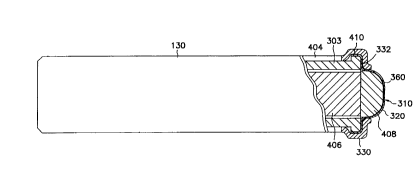
Fig. 3 is a side view of the electrode end 130 of a bipolar lead for
electrically stimulating and monitoring the heart. The implantable electrode
end
130 shown has a cylindrical body having one proximal electrode 306 and one
distal electrode 310. Both the proximal 306 and distal 310 electrodes are made
of electrically conductive, corrosion resistant material, and are of
cylindrical
configuration. This proximal electrode serves as the anode. There are many
different types of proximal electrode configurations that are used for
different
lead applications. The base 303 (shown in Fig. 4) of the electrode end 130 is
formed from a metal, such as titanium or an alloy of titanium which is
electrically conductive but resistant to corrosion and suitable for
implantation in
the body. The base 303 (shown in Fig. 4) is covered with a biocompatible
insulative material 404, such as silicone rubber tubing. The electrode end 130
also includes the distal electrode 310. The distal electrode includes a screen
320
and a masking component 330. The screen 320 is attached to the base 303 (see
Fig. 4). The masking component 330 is positioned over the shoulder 332 and
over a portion of the screen 320. A set of tines 312 is attached to the
insulative
tubing material 404. Tines 312 are used for passive fixation of the distal
electrode 310 in the desired location proximate to the heart tissue. The tines
312
are designed to engage cardiac structures within the right ventricle or right
atrium to provide acute and chronic anchoring of the electrode. The molded
rubber tine neck component is bonded to the conductor coil insulation tubing
404 and the electrode tip body. The tines are located between the proximal and
distal electrodes. Although tines 312 (see Fig. 3) are shown, it is
contemplated
that other forms of fixation, such as a helix for active fixation into the
heart
could also be used to anchor the electrode.
CA 02277930 1999-07-14
WO 98131419 PCT/US98/00675
6
The mask component 330 is made of an insulative elastomeric
material. Silicone rubber tubing is a biocompatible material used to make the
mask component 330. The screen 320 is of a porous construction. A screen is
made of electrically conductive, corrosion resistant material. Using a screen
320
having a porous construction allows for fibrotic ingrowth. This provides for a
further anchoring of the distal end 130 and also increases the sensing
capability
of the distal electrode 310. The sensing capability is enhanced because the
porous screen 320 has more surface area than a corresponding flat piece of
material. The ingrowth of fibrotic tissue into the screen 320 provides contact
with the increased amount of surface. As can be seen from Fig. 3, the screen
320
which makes up the distal electrode 310 has a diameter which is smaller than
the
outside diameter of the cylindrical body or base 303 of the electrode end 130.
The outside diameter of the cylindrical body or base 303 is of a diameter
believed to be sufficient so as not to perforate the heart wall. At the
junction of
the screen 320 and the base 303, a shoulder 332 is formed. The shoulder limits
the depth to which the distal electrode 310 penetrates the endocardium or
heart
muscle. The screen 320 is shaped somewhat like a hat in that it has a rim and
a
convex portion. The rim of the screen 320 abuts the shoulder 332.
Fig. 4 shows a partial cross-sectional view of the electrode end
130. The distal portion of the electrode end 130 is provided with a central
bore
406. Contained within this central bore 406 is a silicone steroid matrix which
elutes steroid to decrease inflammation. The internalized silicone matrix
containing a steroid is one method for delivering steroid to an area around
the
distal electrode 310. There are other methods and apparatus that can be
employed to deliver steroid to the tissue surrounding the distal electrode
310,
such as an external steroid matrix that forms a ring around the lead body near
the
electrode end 130. It is also contemplated that this invention may be used for
any of a number of different applications and that in some instances it may be
unnecessary to use a steroid or drug delivery system.
A multifilar conductor coil within the lead body 120 electrically
contacts the base 303 and the screen 320. More specifically, electrical
contact is
made between the helical coil conductors and the portion of the screen
CA 02277930 1999-07-14
WO 98131419 PCT/US98/00675
7
uncovered by the masking component 330, now referred to as electrical contact
surface 360. The surface of screen 320 of the distal electrode 310 is of
porous
construction and has a nominal pacing surface area in the range of 1.7-2.6
mmz.
It has been found that a nominal pacing area of about 2.0 mm2 provides a
contact
surface with adequate sensing and high enough impedance.
The size or area of the contact surface 360 is selected so as to
optimize several competing design factors. The area of the contact surface 360
has to be large enough so that the electrode can adequately sense the
electrical
signals of the heart. The area of the contact surface also has to be small
enough
so that a high impedance is produced to minimize the energy necessary to pace
the heart.
The distal portion of the central bore 406 also includes a ball 408
of wound electrically conductive, corrosion-resistant material that is
commonly
referred to as a mesh ball. The mesh ball 408 sits inside the screen 320
within
the central bore 406. The function of the mesh ball is to increase the sensing
surface area of the distal electrode 310 without increasing the pacing surface
area. Both the pacing and the sensing surface areas are important parameters
of
the lead system. The pacing surface area is determined by the exposed screen
320 of the distal electrode 310. The sensing surface area is determined by the
exposed electrical surfaces both external and internal to the porous tip of
the
distal electrode 310. The sensing capability is enhanced by the mesh ball 408
since it tends to act like foil on a TV antennae. It should be noted that the
mesh
ball 408 is not necessarily needed to practice this invention. It does provide
some added benefits, as listed above, and also helps the screen 320 maintain
its
shape.
The electrical contact surface 360 of the distal electrode 310 is
defined by the addition of a masking component 330 applied to the base 303 and
over the screen, 320. The masking component 330 is a snort length of silicone
rubber tubing which stretches over the end of the distal electrode 310 and
covers
a portion of the screen 320. The masking component 330 also stretches over the
shoulder 332 on base 303. The size or area of the electrical contact surface
360
is defined by the amount of silicone tubing used to mask the screen 320. If
less
i
CA 02277930 1999-07-14
WO 98/31419 PCT/US98/00675
8
area is desired for the electrical contact surface 3C0, a longer masking
component 330 is used. The nominal surface area of the electrical contact
surface is 2.0 mm2. The masking component 330 is held in place primarily by a
compressive force which occurs after the elastomeric material is stretched
over
S the base 303 and a portion of the screen 320. A medical adhesive 410
provides a
secondary holding force between the base 303, the screen 320, and the masking
component 330.
An additional advantage of using silicone rubber tubing for the
masking component 330, is that this material has been implanted within humans
previously and the characteristics of that material in that environment are
well
known. The use of a masking component 330 is less dependent on a new
technology, which makes the solution much more economical than other
solutions. The open window of electrically active mesh will make tissue
contact
in vivo and determine the pacing impedance of the lead.
It is to be understood that the above description is intended to be
illustrative, and not restrictive. Many other embodiments will be apparent to
those of skill in the art upon reviewing the above description. The scope of
the
invention should, therefore, be determined with reference to the appended
claims, along with the full scope of equivalents to which such claims are
entitled.