Note: Descriptions are shown in the official language in which they were submitted.
CA 02277948 1999-07-14
WO 99/26879 PCT/US98/24429
RIGID THERMOPLASTIC SQUEEZE CONTAINER HAVING
SELF-SEALING DISPENSING VALVE
Field of The Invention
The present invention is to a thermoplastic squeeze
container for a flowable substance and more particularly to a
thermoplastic squeeze container incorporating a self-sealing
dispensing valve or closure.
Background of the Invention
Thermoplastic containers are used to package and
dispense numerous flowable substances, such as powders, pastes
or liquids. Of special interest are squeezable containers,
such as bottles or tubes formed of thermoplastic material
which containers are squeezed, by application of pressure on
the sidewall of the container, so as to dispense a flowable
substance from an orifice in a neck formed on the container.
In order to provide a thermoplastic squeeze container, the
wall of the container must be l:ormed of a thermoplastic
material that will flex so as to enable forcing of the
flowable substance therefrom. Generally, such thermoplastic
squeeze containers, after squeezing, are retained in the shape
formed when a flowable substance is dispensed, i.e. in a
somewhat collapsed condition. _
In certain instances, it is desirable to use a self-
sealing or self-closing valve in combination with a
thermoplastic squeeze container. Examples of such containers
containing self-sealing valves are, for example, shown and
described in U.S. 5,033,655 and U.S. 5,213,236. As described
1
SUBSTITUTE SHEET (RULE 28)
CA 02277948 1999-07-14
WO 99126879 PGT/US98/Z4429
in these patents, a dispensing package may contain a self-
sealing valve which securely seals upon cessation of pressure
on the side wall of the container, so as to protect the
contents thereof from the atmosphere, but upon squeezing of
the side wall the contents will be dispensed. The use of a
self-sealing valve in combination with a tube shaped container
is suggested in U.S. 5,033,655 and illustrated generally in
Figures 6 and 7 of that patent. In. order to use such a self-
sealing valve in a tubular container, however, the side wall
of the tubular container must have a specific rigidity or
thickness such that, while being squeezable, the side wall
will return to the shape that existed before squeezing such
that air will be sucked back into the container body so as to
close the self-sealing valve. The formation of such thick-
walled tubular containers is expensive and requires special
equipment.
The formation of tubular containers from a
longitudinally stretched, extruded,. thermoplastic cylinder has
been effected in an economical, efficient, and commercially
viable method, such as described in U.S. 3,047,910 to Downs,
apd U.S. 5,069,856 to Holoubek & Rhoades. These methods are
somewhat limited, however, in that a wall thickness of about
0.012 to 0.025 inch is about the maximum wall thickness that
can be efficiently and economically achieved. Thus, such a
method is generally not suited for producing thick walled
tubes for use in a tubular container containing a self-sealing
valve, as previously described.
2
SUBSTITUTE SHEET (RULE 2B)
CA 02277948 2006-06-27
79310-2
It is an object of the present invention to
provide a thermoplastic squeeze container containing a
self-sealing dispensing valve the container having a side
wall that is squeezable to dispense flowable material
therefrom but having sufficient rigidity such that the side
wall returns to a non-collapsed position upon release of
pressure on the side wall so as to suck in and close the
self-sealing valve.
Summary of the Invention
In one broad aspect, there is provided a
thermoplastic squeeze container for containment and
dispensing of a flowable substance comprising: a
cylindrical shell having a cylindrical body portion with an
inner surface and an outer surface, a first sealable open
end and an opposed end having a head portion forming a
dispensing orifice; a self-sealing dispensing valve in said
head portion closing said dispensing orifice, and; a
cylindrical support sleeve of thermoplastic material having
an outer surface, contained within said cylindrical body
portion, the outer surface of which is contiguous with said
inner surface of said cylindrical body portion and extends
from a position adjacent said head portion to a location
adjacent to the first sealable end of said cylindrical body
portion such that said end can be sealed by closing said
cylindrical body portion without interference by said
cylindrical support sleeve.
In another broad aspect, there is provided a
thermoplastic squeeze container for containment and
dispensing of a flowable substance comprising: a
3
CA 02277948 2006-06-27
79310-2
cylindrical shell, formed from a longitudinally stretched,
extruded, thermoplastic cylinder, having a cylindrical body
portion with an inner surface and an outer surface, a first
sealable open end an opposed end having a head portion
forming a dispensing orifice; a self-sealing dispensing
valve in said head portion closing said dispensing orifice,
and; a cylindrical support sleeve of thermoplastic material,
formed from a longitudinally stretched, extruded,
thermoplastic cylinder, having an outer surface, contained
within said cylindrical body portion, the outer surface of
which is contiguous with said inner surface of said
cylindrical body portion and extends from a position
adjacent said head portion to a location adjacent to the
first sealable end of said cylindrical body portion such
that said end can be sealed by closing said cylindrical body
portion without interference by said cylindrical support
sleeve.
In yet another broad aspect, there is provided a
thermoplastic squeeze container for containment and
dispensing of a flowable substance comprising: a
cylindrical shell, formed from a longitudinally stretched,
extruded, thermoplastic cylinder, having a cylindrical body
portion with an inner surface and an outer surface, a first
sealable open end and an opposed end having a head portion
forming a dispensing orifice, said head portion including a
shoulder having an inner surface; a self-sealing dispensing
valve in said head portion closing said dispensing orifice;
a downwardly depending flange on the inner surface of said
shoulder, spaced from the inner surface of said cylindrical
body portion and sized so as to trap an end of a cylindrical
support sleeve between the downwardly depending flange and
the cylindrical body portion and; a cylindrical support
sleeve of thermoplastic material, formed from a
3a
CA 02277948 2006-06-27
79310-2
longitudinally stretched, extruded, thermoplastic cylinder,
having an outer surface, contained within said cylindrical
body portion, the outer surface of which is contiguous with
said inner surface of said cylindrical body portion and
extends from a position adjacent said head portion to a
location adjacent to the first sealable end of said
cylindrical body portion such that said end can be sealed by
closing said cylindrical body portion without interference
by said cylindrical support sleeve, with an end of said
cylindrical support sleeve trapped between the flange of
said shoulder and said cylindrical body portion.
Preferably, both the cylindrical shell and the
support sleeve are formed from a longitudinally stretched,
extruded, thermoplastic cylinder, and the outer surface of
the cylindrical support sleeve is bonded to the inner
surface of the cylindrical body portion, such as by sonic
welding.
3b
CA 02277948 1999-07-14
WO 99/2689 PCTNS98/24429
In another embodiment, a downwardly extending flange
is provided on a shoulder of the head portion of the
cylindrical body portion which is spaced from the inner
surface of the cylindrical body portion and traps or seats an
end of the cylindrical support sleeve between the flange and
the cylindrical body portion.
Brief Description of the Drawings
The present invention will be more fully understood
by reference to the following description and accompanying
drawings illustrating a preferred embodiment thereof, wherein:
Figure 1 is a sectional view through a rigid
thermoplastic squeeze container having a self-sealing
dispensing valve according, to the present invention before
filling with a flowable substance;
Figure 2 is a sectional view as in Figure 1 showing
the squeeze container filled with a flowable substance and
with the first open end sealed;
Figure 3 is a sectional view as in Figure 2 showing
the squeeze container after a portion of the flowable
substance has been dispensed therefrom;
Figure 4 is a view taken along the line IV - IV of
Figure 3;
Figure 5 is a view taken along the line V - V of
Figure 3;
Figure 6 is a view similar to Figure 4 showing the
container with application of pressure on the side wall of the
container to dispense flowable substance therefrom;
4
SUBSTITUTE SHEET (RULE 28)
krB
CA 02277948 1999-07-14
WO 99/26879 PCT/US98IZ4429
Figure 7 is a sectional view through a rigid
thermoplastic squeeze container having a self-sealing
dispensing valve according to another embodiment of the
present invention;
Figure 8 is a view taken along lines VIII - VIII of
Figure 7 showing a downwardly depending flange; and
Figure 9 is a view similar to Figure 8 showing the
use of a plurality of flange sections.
Detailed Description
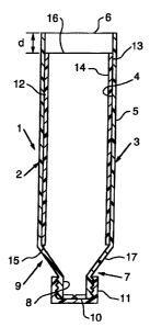
Referring now to the drawings, one embodiment a
thermoplastic squeeze container 1, for containment and
dispensing of a flowable substance has a cylindrical shell 2
with a cylindrical body portion 3 that has an inner surface 4
and outer surface 5. The cylindrical body portion 3 has a
ffirst sealable open end 6 and a head portion 7 that forms a
dispensing orif ice 8 at the opposite or second end 9 of the
cylindrical body portion 3.
A self-sealing dispensing valve 10 is provided in
the head portion 7 which closes the dispensing orifice 8. A
cap 11 may be provided to enclose the self-sealing dispensing
valve 10 during, filling, shipping and storage of the
thermoplastic squeeze tube.
Examples of the type of self-sealing dispensing
valves that may be used in the thermoplastic squeeze tube of
the present invention are those described in U.S. 4,991,745,
U.S. 5,033,655, U.S. 5,213,236, U.S. 5,339,,995, U.S.
SUBSTITUTE SHEET (RULE 28)
CA 02277948 2006-06-27
79310-2
5,377,877, U.S. 5,409,144, U.S. 5,439,143.
A cylindrical support sleeve 12 of thermoplastic
material having an outer surface 13, inner surface 14, first
end 15, and second end 16 is contained within the
cylindrical body portion 3. The outer surface 13 of the
cylindrical support sleeve 12 is substantially contiguous
with the inner surface 4 of the cylindrical body portion 3,
and the cylindrical support sleeve 12 extends from a
position adjacent the head portion 7 to a location adjacent
the first sealable end 6 of the cylindrical body portion 3,
but spaced therefrom a distance d such that the fist
sealable end 6 can be sealed by closing the same without
interference by said cylindrical support sleeve 12. The
first end 15 of the cylindrical support sleeve 12 is
adjacent a neck portion 7 of the cylindrical body portion 3,
while the second end 16 is adjacent but spaced from the
sealable open end 6 of the cylindrical body portion 3 so
that the open end may be sealed, as shown by a seal 18 in
Figure 2, such as by heat sealing of the open end 6, after a
flowable substance S has been charged thereto.
The outer surface 13 of the cylindrical support
sleeve 12 may be bonded to the inner surface 4 of the
cylindrical body portion 3 by bonding techniques, such as by
use of an adhesive or by sonic welding.
The thermoplastic body portion 3 and the
cylindrical support sleeve 12 may be formed from the same or
different thermoplastic materials, such as low density
polyethylene which has a density of between about 0.910 to
0.925 g/cm3, as identified by ASTM standards, or a high
density polyethylene which has a density of between about
0.941 to 0.959 g/cm3. In addition to polyethylene, other
6
CA 02277948 2006-06-27
79310-2
thermoplastic materials may be used, such as polypropylene,
polyvinyl chloride, and the like.
The cylindrical shell 2 from which the cylindrical
body portion 3 is made, and also the cylindrical support
sleeve 12 are both preferably formed from a longitudinally
stretched, extruded, thermoplastic tube, and may be a single
layer or a multi-layer or laminate material. Such extrusion
and stretching techniques are known, for example, as
described in U.S. 5,069,856 which is assigned to the
assignee of the present invention.
As an example of the type of thermoplastic squeeze
container of the present invention, a cylindrical body
portion 3 would preferably have a wall thickness of between
about 0.015 to 0.021 inch and an interior diameter of
slightly larger than about 2 inches, in which a cylindrical
support sleeve of an outer diameter of about 2 inches and a
wall thickness of between about 0.015 to 0.027 is provided.
The first end 15 of the cylindrical support sleeve 12 would
extend from a portion adjacent the neck portion 7 to a
distance where the second end 16 is spaced from the open end
6 of the cylindrical body portion 3 of about 0.25 inch or
more which will enable sealing of the open end 6 without
interference by the cylindrical support sleeve 12.
7
CA 02277948 1999-07-14
WO 99/26879 PCT/US98/24429
Another embodiment of the thermoplastic squeeze
container of the present invention is illustrated in Figure 7,
where the structure is adapted to trap the first end 15 of the
cylindrical body portion. As illustrated, the thermoplastic
squeeze container 1' has a cylindrical shell 2 with a
cylindrical body portion 3 having an inner surface 4 and outer
surface 5. A first sealable open end 6 is provided, as is a
head portion 7 forming a dispensing orifice 8 at the opposite
end of the cylindrical body portion 3. A self-sealing
dispensing valve 10 is provided in the head portion which
closes the dispensing orifice 8. As in the first embodiment
described, a cylindrical support sleeve 12 of thermoplastic
material has an outer surface 13, an inner surface 14, a first
end 15 and second end 16, which cylindrical support sleeve is
contained within the cylindrical body portion 3. The outer
surface 13 of the cylindrical support sleeve 12 is contiguous
with the inner surface 4 of the cylindrical body portion 3 and
extends from a position adjacent the head portion 7 to a
location adjacent the first sealable end 6 of the cylindrical
body portion 3, but spaced therefrom a distance ~ from sealing'
of the first sealable end 6. In the embodiment of Figure 7,
the head portion has a neck portion 7 which has a shoulder 19
connecting the neck portion 7 with the cylindrical body
portion 3. A downwardly depending flange 20 is provided on
the inner surface 21 of the shoulder 19 which is spaced from
the inner surface 4 of the cylindrical body portion 3 a
distance d' that is sized so as to trap the first end 15 of
the cylindrical support sleeve 12 between the downwardly
8
SU6STiTUTE SHEET (RULE 2B)
CA 02277948 1999-07-14
WO 99/26879 PCTNS98/24429
depending flange 20 and the cylindrical body portion 3. The
flange may be a continuous flange (Figure 8) or in the form of
at least one flange section (Figure 9) extending partially
about the inner circumference of said cylindrical sleeve, such
as flange sections 20a, 20b and 20c illustrated in Figure 9.
With the use of a cylindrical shell and a
cylindrical support sleeve to produce the squeeze containers
of the present invention, conventional filling and sealing
equipment can be used as the same acts in the manner of a
container or tube of conventional design but having a thicker
wall. The self-sealing dispensing valve may be a single layer
of material or may be a composite material such as one having
barrier properties.
The thermoplastic squeeze container of the present
invention provides excellent protection for the contents of
the container from the environment,. while enabling squeezing
of the cylindrical body portion to dispense a desired amount
of contents therefrom, with the combined rigidity of the
cylindrical body portion and cylindrical support sleeve
returning to rest or unsqueezed position to ensure suck-back
and closure of the self-sealing valve.
9
SUBSTITUTE SHEET (RULE 26)