Note: Descriptions are shown in the official language in which they were submitted.
CA 02278091 1999-07-15
WO 98/34402 PCT/US98/01720
-1-
METHOD AND APPARATUS FOR LINE OR FRAME-SYNCHRONOUS
FREQUENCY HOPPING OF VIDEO TRANSMISSIONS
BACKGROUND OF THE INVENTION
Technical Field of the Invention
The present invention relates to the transmission of
video signals, and more particularly, to the transmission
of video signals using line or frame synchronous frequency
hopping.
Description of Related Art
The transmission of video signals involves the
transmission of a video luminance signal between a
transmitting and receiving unit. Creation of the video
luminance signal is accomplished by vertical and
horizontal raster scanning of the video images on a video
image tube. The raster scanning includes horizontal line
flyback times during which the video signal is blanked to
the black condition by a line synchronization pulse while
the scan returns back to the initial position for the next
horizontal line. Vertical scan synchronization pulses are
transmitted during a vertical frame flyback time wherein
the scan returns from a lower right-hand to an upper or
left-hand corner of a video frame.
FIGURE 1 illustrates a prior- art video wave form used
for video transmission. A video signal 2 represents
variations in image intensity over a period in time. The
video signal 2 is separated into a plurality of line scan
periods 4 which are separated by regular occurrences of
line sync pulses 6. The video signal 2 is blanked to the
black level during the line scan flyback time to prevent
unwanted lines as the scan spot returns from right to left
on the screen. For color video images, a chrominance
signal (not shown) is added to the video signal. However,
this does not materially alter the appearance of the video
waveform depicted in FIGURE 1.
CA 02278091 1999-07-15
WO 98/34402 PCTIUS98/01720
-2-
After each 625 line period, a frame sync pulse 8 is
inserted to indicate the separation between two video
frames. The frame sync pulse 8 allows the frame scan to
return to the top of the next video frame during the frame
flyback time. The frame sync pulse synchronizes the
vertical scan generator at the video signal receiver. The
video signal, is blanked to the black level during the
frame flyback period to prevent generation of diagonal
lines on the screen as the spot returns from the bottom
right to the top left of the video frame.
When:iriterlacing is used, every other horizontal line
of the video frame is presented over two vertical scan
periods. The vertical scan returns from the bottom right
to the top left after approximately half the line periods
and starts a new vertical scan to fill-in the alternate
lines that were not included in the first half scan.
Interlacing allows half of the horizontal lines to be
updated twice as frequently, reducing image flicker and
providing improved response to movement of the image. A
complete image of 625 lines is thus transmitted every two
vertical scan periods.
Conventional video broadcasts have used vestigial
sideband amplitude modulation. This is a form of double-
side band amplitude modulation in which the higher video
frequency components of one sideband are suppressed by a
filter to reduce transmission bandwidth requirements. The
vestigial sideband transmissions are sensitive to
interference. Thus, transmitters that are allocated the
same channel frequency must be widely geographically
spaced to prevent any interference.
Frequency modulation may alternatively be used to
transmit the composite video signal in a manner that is
much less sensitive to interference. However, frequency
modulation requires a much wider bandwidth. FM video
transmission is utilized in broadcast satellite/electronic
news gathering services (BAS/ENG). The system utilizes
an ad hoc c=hannel allocation scheme whereby an ENG service
CA 02278091 1999-07-15
~ .", ,.. .
, , = ,. , .
= = = . = ~ y ~ ~ = ,
. , s =
= ~ s s = =
-3-
wishing to temporarily setup within a given area applies
for a frequency to a frequency allocating service.
The frequency allocating service allocates a
frequency with regard to other users that may be close
enough to create interference between signals. Individuals
already utilizing the same frequency must be far enough
away to cause no perceptible video picture degradation.
The frequency allocating service must allocate frequencies
on a conservative geographical spacing to guarantee non-
interference. Conservative geographical spacing however
reduces the efficiency of spectral use creating a poor
utilization of resources. Therefore, a system enabling
better utilization of video frequency transmission
resources would be greatly beneficial.
Patent Document W096/29824, published September 26,
1996, discloses a cellular system for distributing a
plurality of television programs in a desired service
area. The presentation of one program to a user entails
selecting one of the channels, selecting data from the
multiplexed stream of digital data and reproducing the
selected data as the sensorially perceptible information.
SUMMARY OF THE INVENTION
The present invention overcomes the foregoing and
other problems with a new method and apparatus for
transmitting a video signal using frequency hopping
techniques. The transmission portion of the system
includes a modulator for modulating the video signal onto
a radio frequency carrier selected from a plurality of
radio frequency carriers. The carrier is varied according
to a prearranged frequency hopping pattern.
Frequency hopping synchronization codes are inserted
within the modulated video signal by stripping existing
line and frame synchronization codes from the video frame
and inserting in their place a frequency hopping
synchronization code and a frequency changing guard
period. Frequency hopping synchronization codes indicate
which frequency carrier is carrying a particular line or
AMcNDED SHEET
CA 02278091 2003-01-27
3a
frame of the video signal. The frequency changing guard
period provides a period of dead time during which a
carrier frequency may be changed from one frequency to
another within the preselected frequency hopping pattern.
More specifically, the present invention provides a
method for transmitting a video signal having improved
immunity to signal interference, modulating the video
signal onto a radio frequency carrier selected from a
plurality of radio frequency carriers, the method
comprising replacing line synchronization pulses with a
frequency hopping synchronization code, varying the
selected radio frequency carrier according to a prearranged
pattern, and tuning a radio receiver to receive the video
signal on the selected radio frequency carrier according to
the prearranged pattern.
The present invention also provides a method for
transmitting a frequency hopped video signal, detecting
synchronization pulses within a video signal, the method
comprising replacing the detected synchronization pulses
with a frequency hopping synchronization code, modulating
the video signal onto a selected radio frequency carrier
selected from a plurality of radio frequency carriers, and
varying the selected radio frequency carrier among the
plurality of radio frequency carriers according to a
prearranged pattern in response to the frequency hopping
synchronization code.
The present invention also provides a method of
receiving a frequency hopped video transmission, and
detecting a frequency hopping synchronization code within
CA 02278091 2003-01-27
3b
the frequency hopped video signal, the method comprising
tuning a receiver to receive the video signal on a radio
frequency carrier selected from a plurality of radio
frequency carriers according to a prearranged pattern in
response to the frequency hopping synchronization code,
replacing the detected frequency hopping synchronization
code with a synchronization signal within the video signal,
and changing the radio frequency carrier according to the
prearranged pattern between synchronization signals.
The present invention also provides an apparatus for
transmitting a frequency hopped video signal, the apparatus
comprising means for processing a composite video signal to
detect synchronization pulses within the composite video
signal and replacing the detected synchronization pulses
with a frequency hopping synchronization code, means for
generating a plurality of carrier frequencies according to
a prearranged pattern in response to the frequency hopping
synchronization code generated by the means for processing,
and a modulator for modulating the video signal including
the frequency hopping synchronization code with a carrier
frequency associated with the synchronization code.
The present invention also provides an apparatus for
receiving a frequency hopped video signal, having a
detector for detecting a frequency hopping synchronization
code within a receive frequency hopped video signal, the
apparatus comprising a frequency hopping controller
responsive to detection of the frequency hopping
synchronization code for generating control signals
indicating a frequency hopping sequence of a carrier
CA 02278091 2003-01-27
3c
frequency of the received frequency hopped video signal,
and means for removing the detected frequency hopping
synchronization code and inserting video frame and line
synchronization codes.
The present invention also provides a frequency hopped
video signal receiver having a frequency hopping receiver
for receiving a frequency hopped video signal and
generating a demodulated video signal and a memory for
storing at least one video frame of the demodulated video
signal, the receiver comprising an A/D converter for
digitizing the demodulated video signal prior to storage in
the memory, and a processor for determining if errors exist
within the at least one video frame by comparison to
preselected criteria and for correcting any detected errors
in an output composite video signal.
The present invention also provides an apparatus for
transmitting and receiving a frequency hopped video
signals, the apparatus comprising means for removing frame
and line sync codes from a composite video signal and
inserting frequency hopping synchronization codes to
generate a modified video signal, means for modulating the
modified video signal using a frequency hopped carrier
signal, the means for modulating located at a transmitter,
and means for removing the frequency hopping
synchronization codes and inserting the frame and line
synchronization codes to reconstitute a composite video
signal, the means for removing located at a receiver.
CA 02278091 1999-07-15 , = , ,
,.~ ., ..
-4-
A radio receiver is tuned to receive the frequency
hopped video signal on a selected radio frequency carrier
according to the prearranged pattern. At the radio
receiver, the frequency hopping synchronization codes are
detected and used to control the tuning of the radio
receiver. The detected frequency hopping synchronization
codes are removed from the video signal and the line and
frame synchronization codes are reinserted. The received
video signal may also be digitized and processed by a
combination memory and digital signal processor
configuration which detects transmission errors within the
video signal according to preselected criteria. Portions
of the video signal not meeting these criteria may be
corrected by replacing the erroneous portion with another
line or frame from the transmitted video signal.
BRIEF DESCRIPTION OF THE DRAWINGS
For a more complete understanding of the present
invention, reference is made to the following detailed
description taken in conjunction with the accompanying
drawings wherein:
FIGURE I is an illustration of a prior art video
signal;
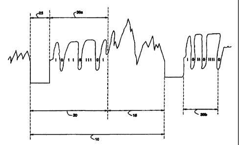
FIGURE 2 is a illustration of a frequency hopped
video signal including a frequency changing time and a
line sync code;
FIGURE 3 is a block diagram illustrating a frequency
hopping video signal transmitter;
FIGURE 4 is a block diagram of a frequency hopping
video receiver without interference mitigation;
FIGURE 5 is a block diagram of a frequency hopping
receiver including interference mitigation processing; and
FIGURE 6 is a flow chart illustrating the
functionalities performed by the processor of the
frequency hopping receiver.
WcNDEG SHEET
CA 02278091 1999-07-15
, . = ,., ,,,
.. .,,.'
-5-
DETAILED DESCRIPTION OF THE INVENTION
Referring now to the Drawings, and more particularly,
to FIGURE 2, wherein there is illustrated the frequency
hopped video signal of the present invention. The video
signal includes two line scan periods 10 wherein each line
scan period includes all of the necessary information for
recreating a single line of a video frame. The line scan
period 10 includes the luminance/chrominance signal 15 and
the horizontal scan flyback period 20. The video
luminance/chrominance signal 15 represents the variation
in image intensity over a line period of a video frame.
The horizontal scan flyback period 20 provides the time
necessary for the raster scan to return from the left-hand
to the right-hand side of the video frame.
The length of a line scan period 10 of the present
invention is the same as that of a presently existing line
scan period, as is the length of the horizontal scan
flyback period 20. However, the horizontal scan flyback
period 20 is divided into a frequency changing guard
20 period 25 and a line sync code 30. The frequency changing
guard period 25 provides a time slot during which a
frequency hopped carrier signal may be switched between
frequencies. The line sync code comprises a binary code
identifying the line number of the video frame with which
the line scan period 10 is associated. For example, line
sync code 30a is a 10 bit code (1011011101) which
translates into line number 733, while line sync code 30b
identifies the next line number 734. Code patterns such
as 0000000000 and 1111111111 are avoided due to their
difficulty of detection. By identifying each line number
of a video frame with a separate line sync code, no
specific frame sync signal is required. This is due to the
fact that the start of the frame is always indicated by
the first line number of the frame thus eliminating the
need for frame sync coding signals.
CA 02278091 1999-07-15
WO 98/34402 PCTIUS98/01720
-6-
Referring now to FIGURE 3, there is illustrated a
frequency hopped video signal transmitter. A lens 40
focuses an image on the light sensitive electrodes of a
video tube 45. A light dependent electric charge is
generated on the: surface of the light sensitive electrode
reproducing the pattern of the image in a corresponding
pattern of electric charge. A horizontal scan generator
50 and a vertical scan generator 55 deflect an electron
beam within the video tube 45 to scan the light sensitive
electrode and detect the electric charge sequentially at
different points along horizontal scan lines until the
entire charge image is scanned. This comprises a single
video frame. The process then repeats for the next frame.
The sequential electric charge variations detected by the
electronic beam are output as a luminance signal (in the
case of a monochrome video) or as a luminance signal
representing one of three primary color components of the
image (in the case of a color video).
A color camera may comprise three video tubes 45.
Each video tube 45 corresponds to a different primary
color component. The three color component signals are
converted prior to transmission into a luminance signal
and a chrominance signal by an RGB to composite-video
converter (not shown).
A line sync switch 60 is synchronized by a control
signal from the horizontal scan=generator 50 to insert
within the video signal a blanking signal or line sync
pulse during the horizontal scan flyback period 20 (FIGURE
1)= Similarly, a frame sync switch 65 is synchronized by
the vertical scan generator 55 to insert a frame sync
signal within the video signal during a vertical scan
flyback period. It should be appreciated that in
alternative embodiments the video tube 45 may
alternatively be replaced by a solid state device.
The video signal from the camera 35 is fed to a sync
processor 70 to synchronize frequency hopping of the video
signal from the television camera 35 for transmission.
CA 02278091 1999-07-15
. ... ,.,
. , ,
-7-
The sync processor 70 detects the line and frame sync
signals within the conventional composite video signal and
replaces the conventional sync signals with the frequency
changing guard period 25 and line sync codes 30 described
previously with respect to FIGURE 2. The sync processor
70 keeps track of the proper line sync code 30 to be
inserted for each line of a frame as it is processed.
The sync processor 70 also generates a power-up/down
ramping signal 71 to a transmission power amplifier 80 to
control transmissions during the time period the channel
frequency is being changed. The ramping signal 71
discontinues signal transmission while channel frequencies
are changed and resumes signal transmission upon
completion of a channel frequency change during a
frequency hopping sequence.
The random frequency hopping channel sequence is
generated by a frequency hopping controller 75 in response
to line and frame sync codes transmitted from the sync
processor 70. The frequency hopping controller 75 controls
the manner in which a frequency synthesizer 85 generates
the frequency hopped carrier signal to be modulated with
the video signal. The frequency hopping controller 75 can
be programmed to generate the frequency hopped carrier
signal in a variety of ways.
In a first mode, each line of a video frame may have
an associated frequency wherein the frequency sequence is
constant from frame-to-frame. Alternatively, the sequence
of frequencies used for each line may vary from frame-to--
frame in response to a frame counter. This mode is
referred to as fast frequency hopping transmission of
video since the carrier frequency is changed for each line
of a video frame.
In a second mode of frequency hopping, called slow
frequency hopping transmission of video, the carrier
frequency is only changed between each video frame of a
video signal. Thus, an entire frame would be transmitted
using the same carrier frequency. The carrier frequency
~fr?JLL~ aP ~=, T
CA 02278091 2007-10-19
-8-
would only be changed between frames and not for each line of the frame.
The generated carrier frequency signal from frequency synthesizer 85 is
modulated with the video signal at modulator 90. The modulated signal is then
amplified for transmission to a video receiver by power amplifier 80.
Referring now to FIGURE 4, there is illustrated a video receiver for
receiving a frequency hopped video signal. The video signal transmission is
received
via an antenna 100. The signal is next filtered and amplified using tuned
filters 105
and RF amplifier 110. The tuned filters 105 are dynamically tuned between
carrier
frequencies by tuning controller 115 in response to signals from the frequency
hopping controller 120.
A mixer 125 converts the amplified video signal into a suitable intermediate
frequency signal by heterodyne conversion with a local oscillator signal from
local
oscillator 130. The local oscillator 130 is controlled by frequency
synthesizer 135
which is able to rapidly change frequency in response to control signals from
the
frequency hopping controller 120.
The mixer 125 provides the desired operating channel IF signal. This TF
signal is further filtered and amplified using IF filters 140 and IF amplifier
145 to
obtain a sufficiently high signal level for demodulation. The demodulator 150
demodulates the IF signal to reproduce the composite video signal.
The demodulated video signal from demodulator 150 is. applied to line sync
code detector 155 to determine the line sync code pattern inserted by the sync
processor 70 (FIGURE 2) at the transmitter. The output of the line sync code
detector 155 is a 10 bit code indicating which code was determined to be most
strongly detected. The detection timing, in one example, is related to the
peak
correlation with an anticipated code supplied from the frequency hopping
controller
120. Altematively, the detection timing may be derived from 1/0 level
crossings in
the received sync code signaL
Amended Sheet
CA 02278091 2007-10-19
-9-
Frequency hopping controller 120 utilizes a flywheel sync technique similar
to a phase lock loop for detecting code timing by comparisons with a predicted
timing based on the average past history, and a "speed-up" or "slowdown"
signal
generated to synchronize the frequency hopping controller to the received
signal on
an average basis. The frequency hopping controller 120 then supplies control
outputs
to a line sync switch 160 to blank out the line sync code on the output signal
of the
demodulator 150 and reinsert a conventional video line sync signal. Likewise,
a
control output is supplied to fi-ame sync switch 165 to blank out a line sync
code and
reinsert the conventional frame sync signal.
The frequency hopping techniques utilized by the video signal transmitting
and receiving systems may utilize either random frequency hopping or
orthogonal
frequency hopping. Orthogonal frequency hopping guarantees a number of nearby
users will not select the same frequency channel at the same time and
interfere with
each other. Users that are orthogonal to one another must be synchronized in
time
using, for example, a GPS satellite signal as a timing reference. Users
further away
from the source of interference can employ frequency hopping that is
orthogonal to
their most proximate potential interferers. This forms a second mutually
orthogonal
group that is non-orthogonal to the first orthogonal group. When the total
number of
users is greater than the number of channels available, some frequency reuse
is
inevitable which leads to interference. Using the invention as described
however, the
interference is not always between the same pair of co-channel systems, but
varies
randomly due to the frequency hopping. This gives the benefit known as
"interferer
averaging" and avoids the need to plan for worst case scenarios.
Amended Sheet
CA 02278091 1999-07-15
, _ , , = ,=
, . . .
,,. .. .,
-10-
FIGURE 5 illustrates an alternative embodiment of the
receiver including means for implementing interference
mitigation. A frequency hopping receiver 170 constructed
broadly in accordance with receiver illustrated in FIGURE
4 outputs a demodulated signal to analog-to-digital
converter 175. Analog-to-digital converter 175 samples the
demodulated signal at a frequency at least in accordance
with the maximum horizontal pixel resolution of the video
frame such that at least one sample per pixel is taken.
The sampling rate should also be sufficient to provide an
integral number of samples per symbol or bit of the line
sync code. This enables the line sync code symbols to be
represented by an integral number of pixels of either a
one level or zero level depending on the line number.
The A/D converter outputs samples at a continuous
rate to a buffer memory 180. The buffer memory 180 stores
a plurality of video lines or frames of the video signal.
A digital signal processor 185 is connected to the buffer
memory 180 to enable access to the memory independent
20 of the A/D converter 175. This enables A/D converter 175
to continuously write samples into the buffer memory 180
without noticeably interrupting the operations of the
digital signal processor 185.
The digital signal processor 185 comprises a
highspeed computer capable of performing a variety of
functionalities for detecting and correcting interference
within the received video signal. Referring now to FIGURE
6 there is illustrated a flow chart generally describing
the functionalities performed by the DSP 185. Initially,
a prediction is made at step 190 as to where in memory the
next line of samples to be processed will begin and what
the expected line number of the line will be. Next, a
search is conducted at step 195 around the predicted
location for occurrence of the predicted line number to
determine a maximum point of correlation. Inquiry step
200 determines if the expected line code number was
i~~~~n
CA 02278091 1999-07-15
WO 98/34402 PCTIUS98/01720
-11-
correctly detected near the predicted location or if there
was an error.
If no error occurred, inquiry step 210 determines
whether the beginning of the next line position is too
near to the first sample in a line, and inquiry step 215
determines if the beginning of the next line position is
too far from the first sample in the line. If either of
these conditions occur, control passes to step 220 wherein
the timing generator is instructed to adjust frequency
changes and adjust the sample timing for the A/D
converter. Control then passes back to 190.
If error is detected at step 200, control passes to
inquiry step 225 to determine if the line of video data
has been corrupted by interference. The algorithm for
detecting whether a line of video data is corrupted may
simply involve determining whether the detected line sync
code was equal to the predicted line sync code.
Alternatively, more complex algorithms can be used to
determine whether a.block of consecutive lines in the
frame have a high sync code error rate.
The data may also be flagged as corrupted if the
signal strength indicated by the receiver was unexpectedly
high during one or more lines indicating that a different,
unwanted signal was temporarily received. In the case of
slow frequency hopping, whole frames may be deemed good
or bad by counting how many -line number codes were
correctly received out of the total number of 625 line
codes. A threshold can be placed indicating the number
of errors permitted before a frame is considered
corrupted.
Corrupted information is corrected at step 230 and
the corrected data is output at step 235. Correction of
corrupted data may be accomplished in a variety of
manners. When a frame or line is corrupted, the corrupted
frame or line is merely replaced with a previous or
subsequent frame or line.
CA 02278091 2007-10-19
-12-
More . complex interference mitigation correction algorithms may include the
use
of narrow band frequency excision filters in which samples collected from
memory 180
are frequency analyzed over one or more scan lines using a fast fourier
transform to
determine the presence of a dominant frequency component that is not present
on
adjacent lines or frames. The dominant frequency component is set to zero
before inverse
fourier transforming to obtain a corrected signal with the narrow band
interference
removed. Such techniques are best performed by collecting undemodulated
signals from
the receiver in the form of complex number samples which after correction for
interference are subjected to numerical demodulation algorithms in the DSP
185. An
alternative method of digitizing radio signals while preserving their complex
vector
nature is described in U. S. Patent No. 5,048,059, issued to the Applicant.
Another interference mitigation algorithm for correcting line corrupted data
involves synthetically regenerating a corrupted line of video pixels by
interpolating the
pixel data between adjacent lines of the same fraine, between the same lines
in successive
frames or using the eight lines surrounding a corrupted line number from the
current
fiame, the previous frame and the subsequent frame. The interpolation
algorithm is not
restricted to a linear algorithm. For example, the line of the frame previous
to the
oorrupted line can be correlated with the same line number in the previous
frame and the
next frame to determine the degree of correlation with each. The correlation
coefficients
can be used to form a weighted sum of the line from the previous and next
frames having
the same line number as the corrupted frame, which, in the limit, can mean
selecting
either the same line of the previous frame or the same line of the next frame
to replace the
corrupted line.
Amended Sheet
CA 02278091 1999-07-15
WO 98/34402 PCT/US98/01720
-13-
The interference mitigation algorithm can also be
adapted to the nature of the interference expected. For
example, when the channel frequency selected for a whole
frame is a frequency likely to be utilized by anot.her
frequency hopping system, steps are taken to synchronize
the frame periods of all systems using a GPS satellite.
The interference would then be expected to be frame
synchronousand a bad frame replacement algorithm would
make a good/bad decision on a whole frame basis and
replace the frame if deemed bad.
On the other hand, if the frequency selected for a
frame was in a band shared with mobile satellite services
that have different interference characteristics, such as
interfering with certain number of consecutive lines
rather than a whole frame, then the interference detection
and mitigation algorithm could be momentarily adapted for
that case.
If it is determined at step 210 that the new line
starting position is too near the first sample or is too
far into the line, update timing generator 250 may be
advanced or retarded in order to cause frequency changes
to occur earlier or later for demodulation and decoding
purposes. This will also alter the sample timing for the
A/D converter 175. The update timing generator 250 and
frequency hopping controller 255 control the frequency
hopping receiver 170 and A/D converters 175, 260 to enable
proper demodulation and decoding of the frequency hopped
video signal to regenerate the composite video signal.
Although a preferred embodiment of the method and
apparatus of the present invention has been illustrated
in the accompanying Drawings and described in the
foregoing Detailed Description, it is understood that the
invention is not limited to the embodiment disclosed, but
is capable of numerous rearrangements, modifications, and
substitutions without departing from the spirit of the
invention as set forth and defined by the following
claims.