Note: Descriptions are shown in the official language in which they were submitted.
CA 02278262 1999-07-20
Hingeless, Parallel Storing, Sectional Aperture Covering
Background of the Invention
Field of the Invention
The following invention relates generally to aperture coverings and
specifically to
garage doors.
Related Art
In the interest of brevity, conventional garage doors will first be explained.
There
are three garage door types that constitute the bulk of those currently used
in the United
States. The technical names for each type vary, so the generic names will be
used.
The most commonly used door for both commercial and domestic purposes is the
sectional door. This door includes horizontal panels which are hinged together
along
their lengths. These panels may be either solid or may contain windows. The
ends of
each panel terminate in at least one free turning wheel which travels in a
track. A system
of counterbalancing is usually employed. One system consists of a cable wound
around
an overhead drum which is attached to a shaft upon which is a torsion spring.
The other
end of the cable is attached to the bottom edge of the door. Another system
uses
extension springs which are fully extended when the door is in the down or
closed
position with the door down. Parts of these counterbalancing systems can break
with
explosive force, creating a hazard that could result in severe injury or
death. When this
door is in the up or open position, it hangs from the track horizontally,
overhead and
parallel to the garage floor. When it is closed, the track and the drive
mechanism remain
CA 02278262 1999-07-20
hanging from the garage ceiling. This precludes the use of this overhead space
for
storage or recreational purposes.
The California door is the second most common garage door. When closed, this
door can appear like a sectional door. This door can be monolithic, however.
Since it
can be made in one piece, it can have better weatherproof qualities and can
possibly be
made less expensively than the sectional door. The California door pivots as a
unit from
the open to closed position. When open, the California door is suspended
overhead and
situated parallel to the garage floor, much like the sectional door. This door
can be
dangerous. Besides the danger of flying spring parts, if the springs fail, the
full weight of
the door can guillotine down through the doorway, creating a hazard that could
result in
serious injury or death. As with the sectional door, the brackets, drives and
door itself
exclude the full use of overhead garage space.
For commercial use, the roll up door is one of the more popular designs. It
wraps
around a counterbalancing spring and is stored in a cylindrical canister above
the
doorway when not in use. Very little usable garage space is taken by the roll
up door
mechanism. This would be an ideal door except for two factors: 1 ) the door
must be
rolled up tightly, and 2) it is difficult to include windows in a roll up
door. With regard
to the first issue, to achieve a small storage canister diameter, the door
must roll up
tightly. Consequently, the individual panels have to be very narrow. These
slats are
approximately 1 to 2" wide, as opposed to the 12 to 18" width common in
sectional doors.
The narrow slats give the door the appearance of a tambour door, like that
commonly
used on a roll top desk. Many home owners find this look aesthetically
unappealing.
-2-
CA 02278262 1999-07-20
With regard to the second issue of windows, the narrow slats also make it
difficult to
include wide windows in the door like those windows preferred by most
homeowners.
While not typically used as a garage door, the prior art teaches a method for
covering an aperture with interlocking, track-contained slats that disengage
when stored
in the aperture open position. The slat design employs minimal
counterbalancing
mechanisms. This method conserves storage space and eliminates exposure to
hazardous
counterbalance components, but the minimal use of counterbalancing components
does
not effectively prevent slat jamming within the track, particularly when
heavyweight slats
are being moved from the aperture closed to aperture open position.
What is needed is an aperture covering that eliminates the hazardous
conditions
created by uncontained, exposed, drive and counterbalance components, while
minimizing the amount of overhead space encumbered by the stored covering,
allowing
for panels large enough to contain aesthetically pleasing windows, and still
providing
sufficient counterbalancing of the aperture cover such that the aperture
covering can be
opened without jamming. These and other shortcomings of conventional doors are
addressed by the present invention.
Summary of the Invention
The present invention is directed to an aperture covering composed of
counterbalanced individual interlocking panels that are disengaged when
stored.
Brief Description of the Figures
The present invention will be described with reference to the accompanying
drawings, wherein:
Fig. 1 is a side elevation of the series of steps for lowering the wall panel
system.
-3-
CA 02278262 1999-07-20
Fig. 2 is a side elevation of the series of steps for raising the panel wall
system.
Fig. 3 is a broken-away sectional view of the drive element of the wall panel
system.
Fig. 4 is a broken-away sectional view of second embodiment of the drive
element
of the wall panel system.
Fig. 5 is a broken-away sectional view of a joint section of the wall panel
system.
Fig. 6 is a broken-away sectional view of a second embodiment of the joint
section of the wall panel system.
Fig. 7 is an elevational view of the wall panel system in a raised position.
Fig. 8 is a broken-away side elevational view of the wall panel system in a
lowered position.
Fig. 9 is a front elevational view of the wall panel system in a lowered
position.
Fig. 10 is a top view of the wall panel system in a closed position.
Fig. 11 is a front elevational view of the wall panel system in a closed
position.
Fig. 12 is a top view of the wall panel system in a partially closed position.
Fig. 13 is a front elevational view of the wall panel system in a partially
closed
position.
Fig. 14 is a top view of the wall panel system in an open position.
Fig. 15 is a front elevational view of the wall panel system in an open view.
Fig. 16 is a broken-away side elevational view of the wall panel system in a
closed position.
Fig. 17 is a broken-away side elevational view of the wall panel system in a
partially open position.
-4-
CA 02278262 1999-07-20
Fig. 18 is a broken-away side elevational view of the wall panel system in an
open
position.
Fig. 19 is an exploded view of the joint of the wall panel system.
Fig. 20 is a top view of the wall panel system in a partially open position.
Fig. 21 is a front elevational view of the wall panel system in a partially
open
position.
Fig. 22 is a top view of the wall panel system in an open position.
Fig. 23 is a front elevational view of the wall panel system in an open
position.
Detailed Description of the Invention
In the following description of the preferred embodiments, reference is made
to
the accompanying drawings which form a part hereof. The description shows by
way of
illustration specific illustrative embodiments in which the invention may be
practiced.
These embodiments are described in sufficient detail to enable those skilled
in the art to
practice the invention, and it is to be understood that other embodiments may
be utilized
and that logical, mechanical and electrical changes may be made without
departing from
the spirit and scope of the present invention. The following detailed
description is,
therefore, not to be taken in a limiting sense.
The invention provides for panels to be stored and retrieved while staying in
a
plane that is substantially parallel to the plane created by the door when
fully deployed.
The invention is not limited to parallelism but can include panel
counterbalancing
mechanisms which allow for panel construction from heavyweight materials. The
invention can include other embodiments where other, non-parallel
configurations, such
as deployment on curved tracks or perpendicular storage of the dissembled
sections are
-5-
CA 02278262 1999-07-20
advantageous. Additionally, other embodiments of the invention include
individual
panels that are curved in one or more planes.
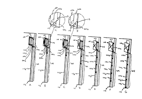
In Fig. 1, the sequence of figures represents an exemplary cross-section of an
aperture covering as viewed from the left side. Hereinafter right and left
refer to one's
perspective outside of the garage looking toward the door. Figures 1 A through
1 G
progressively show positions of the covering as it moves from an open to
closed position.
Figure lA shows the covering in its full open position. In this position, all
of the panels
100a-a are stacked one against the other in parallel fashion in the diamond
shaped storage
box 102 above the aperture 104. The panels 100a-a are completely independent
of each
other with no hinges, cables or other means of connection. The front most
panel 100a is
partially deployed and held there by the counterbalancing mechanism 108, which
is
explained later. As shown in Fig. 7, left rim track 1 l0a and right rim track
1 l Ob capture
the last few inches of each end of the panels to guide their deployment and
prevent panel
disassembly when in use.
In Fig. 1, the covering deployment process is disclosed. There is a compressed
spring or other biasing mechanism 108 at the rear of the storage container
102. A sloping
bottom on the storage container 102 gives a gravity assist to deployment of
the panels
100a-e. The compressed spring biasing mechanism 108 is used together or
separately
with additional biasing mechanisms (see Fig. 3 and Fig. 4), as the application
requires.
The biasing forces push the panel 100a-a faces together within the storage
container 102.
As an operator pulls the first panel 1 OOa down (see Fig. 1 B) the hook-like
nose 112 of the
first panel 100a slides into engagement with the mating groove 114 of the
panel 100b
which it is sliding against (see detailed views 1H and lI), since the first
panel 100a never
-6-
CA 02278262 1999-07-20
leaves the tracks 1 l0a and 1 l Ob (only the left track 1 l0a is illustrated),
first panel 100a
guides the second panel 1 OOb into the top of the tracks 1 l0a and 1 l Ob (see
Fig. 1 D), the
front bottom edge of the storage container 102 being the terminus of the
tracks 1 l0a and
1 l Ob. Likewise, once the second panel 100b is in the tracks 1 l0a and 1 l
Ob, track 100b
will engage (see Fig. 1 D) and guide the third panel 1 OOc into the tracks 11
Oa and 11 Ob
(see Fig. 1 E), and so on until all of the panels 1 OOa-a are deployed and the
first panel
1 OOa contacts the aperture floor 116 (see Fig. 1 G).
Fig. 2 illustrates an example of aperture covering storage, the reverse of the
deployment procedure. An operator lifting on the first panel 100a will be
aided by the
compressed spring counterbalancing system 108 and any additional
counterbalancing
mechanisms (see Fig. 3 and Fig. 4). This system not only offsets much of the
combined
weight of the panels 100a-e, but also prevents the panels 100a-a from wedging
themselves apart in the tracks 1 l0a and 1 l Ob (only the left track 1 l0a is
illustrated) and
jamming the aperture covering. In Fig. 2A, the panels 100a-a are deployed
except for a
portion of the top panel 100e. This panel 100e is holding the expanded biasing
mechanism 108 open. As the top panel 100e is pushed up by the panels 100a-d
below it
1 OOe and the counterbalancing system 108, top panel 100e has to stop against
the top of
the storage container 102 (see Fig. 2B). In detailed drawing 2J, the top panel
100e has
contacted the top of the storage container 102 and the second panel 100d below
top panel
100e is beginning to force top panel 100e out of engagement. In detailed
drawing 2K, the
disengagement is concluded. In Fig. 2E, the panel 100d has pushed completely
past and
forced the top panel 100e against the biasing mechanism 108. Figs. 2F, 2G, 2H
and 2I
CA 02278262 1999-07-20
show the panels 100a-d sequentially disassembling and storing themselves 100a-
d in the
overhead container 102.
Remaining figures 7 through 19 and figures 20 through 23 show other examples
of installed aperture coverings, illustrating that the covering stores
completely out of the
way, while permitting the use of a panel and window style that homeowners
typically
prefer. Furthermore, since most or all of the drive and counterbalance parts
can be
contained in the storage box above the panels, there is little danger of
injury due to
exposed components.
Fig. 3 illustrates an exemplary view of an aperture covering from the left
side.
Track 1 l0a prevents panels 100b and 100c from moving in any direction other
than up or
down. The panels 100b and 100c also cannot disengage because they cannot move
forward or backward far enough to do so. There is a toothed belt 302 at the
front of the
track 1 l0a that engages notches in the end caps 304a or in the faces 304b of
the covering
panels 100b and 100c. This belt 302 can be permanently attached to the bottom
panel of
the door on one end. In one unillustrated embodiment, one end is coiled in
spiral fashion
around a flanged drum attached to a horizontal shaft which rotates in bearings
within a
compartment above the panel storage box. The shaft can have a torsion spring
wound
around it in such a way as to offset all or a portion of the weight of the
covering panels.
In Fig. 3, both ends of the panels 100b and 100c are confined in the front,
back, and sides
by the tracks 1 l0a and 1 lOb (only 1 l0a is illustrated) and toothed belts
302 engaging
them 100b and 100c on both ends. These belts 302 are biased to offset the
panel 100b
and 100c weight by wrapping the belts 302 around drums attached to a common
shaft.
Both panel 100b and 100c ends will move in synchronous fashion up and down
within
_g_
CA 02278262 1999-07-20
the track 110a. The panels 100b and 100c are prevented from moving up or down
relative to each other within the tracks 1 l0a and 1 l Ob because they are
engaged in the
notches 306 of a common belt 302. This prevents panels 100b and 100c from
wedging
apart and possibly jamming within the track 110a.
In Fig. 4 a simplified exemplary cable 402 and ball 404 drive is shown as
another
mechanism for counterbalancing the panels 100b and 100c. Many different drive
types
can be used. In some applications, a drive or counterbalancing system is not
needed or
desired.
Many of the motorized drive systems in use today can be adapted to automate
the
invention, as embodied in Fig. 4. In one unillustrated embodiment, a motorized
drive
system is situated in a compartment within or above the storage container
where the
mechanism would turn the counterbalance shaft in one direction to lower the
door and in
the other to raise it. In another unillustrated embodiment, commonly used
remote
controls and security locks are integrated into the design.
Figs. 7 through 9 illustrate an exemplary vertical up-and-down embodiment of
the
present invention.
Figs. 10 through 15 and Figs. 20 through 23 illustrate an exemplary vertical
side-
to-side embodiment of the present invention, which is, in a particular
embodiment, used
as a closet door. In Fig. 21, two vertical shafts 2102 are attached to the top
edge of each
panel 2104a and 2104b. Two wheels 2106 are attached to each shaft 2102. The
wheels
2106 ride on opposite ledges (one per wheel) within the "C" shaped track 2108
attached
above the aperture 104. When stored in the storage container 102 (see Fig.
22), the back
panel 2104b is biased toward the front panel 2104a (see Fig. 22). When removed
from
-9-
CA 02278262 1999-07-20
the storage container 102 (see Fig. 20), the back panel 2104b wheels 2106 are
guided by a
curved track section 2108 which aids in engaging the back panel 2104b with the
front
panel 2104a as it slides past.
Figs. 16-18 illustrate an exemplary horizontal embodiment of the present
invention. One or more storage containers 102 are located above or below
ground level.
A toothed belt or other drive mechanism can be located under the panels 100 on
one or
both sides of the aperture 104. A SERAPID (meaning "chains that push") brand
or
another powered drive can be used to push/pull the lead panel or to drive the
toothed belt
or other drive mechanism. Above ground storage containers 102 may be disguised
as
benches, equipment storage boxes, or planters for flowers.
Other exemplary embodiments of the claimed invention (not illustrated)
include:
security doors, aircraft hanger doors, shutters, automobile doors, flat roofs,
sloped roofs,
arched roofs, domed roofs, automotive roofs, dance floors, ice skating rinks,
machine
way covers, auditorium walls, gymnasium walls, arena walls, convention hall
walls,
cylindrical buildings, dome buildings, green houses, mobile buildings,
bridges, and
missile silo doors.
The panels can be constructed of a variety of conventional building materials
such
as, e.g., metal, glass, wood, plastic, or fiberglass.
While the invention has been particularly shown and described with reference
to
preferred embodiments thereof, it will be understood by those skilled in the
relevant art
that various changes in form and details may be made therein without departing
from the
spirit and scope of the invention.
-t o-