Note: Descriptions are shown in the official language in which they were submitted.
CA 02278390 1999-07-22
SAFE'Tx SYRINGE
BACKGROUND OF THE ~NVENTxON
(1) Field of the Invention:
The invention relates to a safety syringe, and more particularly to a
syringe which is capable of retracting the needle cannula back into the
barrel and then fixing the cannula in the barrel, after finishing an ejection.
(2) Description of the Prior Art:
Syringes are crucial parts for any medical treatment. To avoid
accidental serum infection from a contagious disease, disposable syringes
are usually used to prevent any syringe from, being re..used. Nevertheless,
inappropriate handling of the disposable syringes after usage was still seen,
and the possibility of infection of a contagious disease for the medical
staffs ox the cleaners from accidental hurt by the disposed needle cannula
always happened. Therefore, the measures of storing the disposed needle
cannula and avoiding accidental infection caused :from being hurt by the
cannula are important topics nowadays while improving the syringe
structure.
Generally, after an injection, the needle cannula is immediately
retracted into and then stored in the barrel for further handling, For
example, in Taiwanese Utility Model Publication No. 165304, an improved
safety syringe structure is taught, in which a mating pair are assigned
respectively to the extruding ring at end of the barrel and the pushing piston
rod on top of the plunger; by providing the mating pair, the injection head
having the needle car~nula can be engaged with the pushing piston rod and
then can be pulled yin so as to be stored completely inside the barrel after
an
injection. In Taiwanese Utility Model Publication No. 356720, a safety
syringe is disclosed, in which a threaded part at the bottom end of the
-1-
CA 02278390 1999-07-22
needle cannula is introduced to be engaged with a small prot~~g block
on top of the plunger fox retracting the needle cannula into the barrel after
usage.
s SUMMARY OF THE rNVEN'Z'xON
Accordingly, it is an object of the present invention to provide a safety
syringe, which can store the needle cannula inside the barrel after an
injection, for preventing accidental infection caused from being stung by
the needle cannula.
It is yet another object of the present invention to provide a safety
syringe, in which the needle cannula can be effectively anchored inside the
barrel for avoiding accidental exposure of the needle cannula and thus
reducing the possibility of personal infection or hurt caused by needle sting.
It is a further object of the present invention to provide a safety syringe,
which has advantages in simple structure, convenient application, and easy
manufacturing.
To achieve all aforesaid objects, the safety syringe of the present
invention comprises a barrel, a plunger, a needle set, and a needle sheath.
The plunger has a rubber piston located at one end thereof, and the rubber
piston includes a conical rod exh uding from a surface thereof. Th;e needle
set includes an adapter having a conical hole thereon, and the conical hole
is surrounded by a plurality of clipping means. A$er an injection, the
conical rod of the rubber piston can be engaged with the conical hole of the
needle set. Thereby, the needle set can be pulled completely into the
barrel by the plunger. Further, the adapter of the needle set has a
protrusion for slanting the needle set in the barrel, so that the needle
cannula can be in contact with the inner wall of the barrel for avoiding
accidental exposure exterior to the barrel.
-2-
CA 02278390 1999-07-22
BRIEF DESCRI~'TION OF THE DRA,'WINGS
The present invention will now be specified with reference to its
preferred embodiments illustrated in the drawings, in which
FIG.1 is an exploded perspective view of an embodiment of the safety
syringe in accordance with the present invention;
FIG.2 is a cross-sectional view of the barrel in the embodiment of
FIG.1;
FIG.3 is a partial cross~sectional view of tl~e plunger in the
embodiment of FIG. I;
FIG.4A is a cross-sectional view of the needle set in the embodiment
of FIG. I;
FIG.4B is an exploded cross-sectional view of the needle set in the
embodiment of FIG.1;
FIG.4C is a bottom view of the needle set in the embodiment of FIG.1;
FIG.4D is a bottom view showing other types of the bottom end of the
needle set in the embodiment of FIG. I;
FIG.SA is a cross-sectional view of the embodiment of FIG. I, showing
the plunger being pushed forward inside the barrel for an injection stroke;
z0 FIG.SB is a cross-sectional view of the embodiment of FIG.I, showing
a pulling-back operation of the plunger after being engaged with the needle
set;
FIG.SC is a cross-sectional view of the embodiment of FIG. l, showing
the needle set being completely received inside the barrel;
FIG.6 is an exploded perspective view of another embodiment of the
safety syringe in. accordance with the present invention;
FIG.7 is a cross-sectional view of the barrel in the embodiment of
FIG.6;
-3-
CA 02278390 1999-07-22
FIG.8 is a partial cross-sectional view of the plunger in the
'' embodiment of FIG.6;
FIG.9A is a cross-sectional view of the needle set in the embodiment
of FIG.6;
FIG.9B is an exploded cross-sectional view of the needle set in the
embodiment of FIG.6;
FIG.9C is a bottom view of the needle set in the embodiment of FIG.6;
FIG.9D is a bottom view showing other types of the bottom end of the
needle set in the embodiment of FIG.6;
1 o FIG.1 OA is a cross-sectional view of the embodiment of FIG .6,
showing the plunger being pushed foxward inside the batxel for an injection
stxoke;
FIG. l OB is a cross-sectional view of the embodiment of FIG.6,
showing a pulling-back operation of the plunger after being engaged with
the needle set; and
FIG.1 OC is a cross-sectional view of the embodiment of FIG.6,
showing the needle set being completely received inside ttze barrel.
DESC TIOi'~1 OF THE PREFERRED EMBODI1V~ENT
The invention disclosed herein is directed to a safety syringe. In the
following description, numerous details are set forth in order to provide a
thorough understanding of the present invention. It will be appreciated by
one skilled in the art that variations of these specific details are possible
while still achieving the results of the present invention. xn other
instances, well-known components are z~ot described in detail in order not
to unnecessarily obscure the present invention.
For simplifying the following descriptions, members with the same
application will be designated by the same reference numexals.
-4-
CA 02278390 1999-07-22
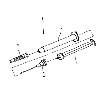
Referring now to FIG.1, an first embodiment of the safety syzinge x in
accordance with the present invention is shown. The safety syringe 1 is a
central type syringe with a needle cannula placed right in the center of front
end of a barrel. The safety syringe i as shown includes a b~nrel 2, a
s plunger 3, a needle set 4 and a needle sheath 5.
Referring to FIG.2, the barrel 2 is a hollow cylindrical body with both
ends open. A front end of the barrel Z is structured as a nozzle 21 with a
reduced inner dianneter_ A, rear end of the barrel 2 is formed into a finger
flange 22.
l0 ~ferring to FIG_3, the plunger 3 for being telescoped inside tltc barrel
Z has a front end carrying a rubber piston 31, in which the rubber piston 31
forms tight contact with the inner wall of the barrel 2 and is capable of
sliding inside the barrel 2. A rear end of the plunder 3 is formed into a
thumb rest 32. Further, the rubber piston 31 has a conical rod 33 located
15 at a central part of a front surface thereof.
Referring to FIG.4A to FIG.4C, the needle set 4 consists of a needle
cannula 41, a needle hub 42 for attehoring the needle cannula 41, and an
adapter 43 for receiving the needle hub 42. Th.e needle set 4 is
telescopically placed inside the nozzle 21 of the barrel 2, with fihe needle
2o cannula 41 being exposed to exterior of tt~e barrel 2.
The needle hub 42 is provided with male threading 44 for meshing
with female threading 45 on the adapter 43, as sho~uc~n in FTG.4A and
FIG.4B.
A rear part of the adapter 43 is formed with a base 46 with a
2s protruding flange. The base 46 further includes a circumferential groove
47 for receiving a rubber seal 48 therein. By providing the rubber seal 48,
a tight contact between the base 46 of the adapter 43 and the nozzle 21 of
the barrel 2 can be established; as shove in FIG.4A and FIG_4B.
The base 46 of the adapter 43 is further formed with a conical hole 49
;0 having a reducing diameter at a bottom thcreof_ As shown in FIG.4C, the
conical hole 49 is surround~d by a plurality of clipping means 50
-s.
CA 02278390 1999-07-22
symmetrically arranged in equal radical intervals. The plurality of clipping
means 50 are formed with angular portions slanting inwards for defining
the profile of the conical hole 49. Further, a protrusion 40 is formed at a
pz~oper location, on the base 46 close to the conical hole 49.
The needle sheath 5 shtown in FZG.1 is located outside the nozzle 21 of
the barrel 2 foz~ shielding the needle cannula 41 of the needle set 4.
In the aforesaid embodiment of the safety syringe 1, the conical hole
49 is located at the center of the base 46 of the adapter 43, with the needle
caanula 41, and the needle hub 42 being aligned with the fluid passage and
i o the conical hole 49 of the adapter 43. Thus, a central inj action-fluid
route
can be established in the needle set 4; as shown in FIG_4A.
Referring to FIG.SA through FIG.SC, a complete application stroke of
the safety syringe 1 in accordance ~xrith the presex~t invention xs shown.
while beginning an injeotion stroke, the plunger 3 is firstly pushed forward
(as shown in FIG.SA). Then, at the moment that the plunger 3 reaches an
extreme positioz~, the conical rod 33 can be received ixoto the conical hole
49 of the adapter 43 _ An engagement can be formed between the plunger
3 and the needle set 4 as the angular portions of the plurality of clipping
means 50 inter-lock the cozucal rod 33, so that the conical rod 33 can be
2o restrained from being taken off and will be firmly held inside the conical
hole 49. After completing the engagement, tl~e plunger 3 is refracted to
pull in the needle set 4 into the barrel 2 through the nozzle 21 (as shown in
FIG.SB). while the needle set 4 is completely stored in the barrel 2,
plastic force from the rubber piston 31 of the plunger 3 urill push away the
25 protrusion 40 of the adapter 43 to make the needle set 4 posed obliquely
inside the barrel 2 (as shown in FIG.SC). At this moment, by providing
the needle set 4 to contact with the inner wall of the barrel 2, accidental
exposure of the needle set 4 can then be substantially avoided.
Referring to FIG.6 to FIG.1 OC, a second embodiment of the safety
30 syringe 1 in accordance with the present invention is shown. Apparently,
the safety syringe 1 in this second embodiment is a lateral type of syringe
-s-
,.w ...
CA 02278390 1999-07-22
with a needle cannula deviated from a centerline of a barrel_
In this embodiment, the conical hole 49 is still formed at the center of
the base 46 of the adapter 43. Different only to the previous embodiment,
the adapter 43 further includes a through-hole 51 aligned with the needle
cannula 41 as well as the needle hub 42. The through-hole 51 located
laterally to the conical hole 49 is used to form a lateral fluid route, as
shown in FIG.9A.
Further, in both the aforesaid erubodiments, four symumetrically-spaced
clipping means 50 (spaced by an angle of 90 degrees) are introduced.
~ov~ever, as required for other applications (such as using different
materials or dimensions), other number of clipping moans 50 can also be
applied. For example, three clipping means 50 (spaced by an angle of 120
degrees) or six clipping means 50 (spacod by an angle of 60 degrees) can
also be allowed in the present invention; as shown in FxG.4D and FIG.9D.
While the present inveatxon has been particularly shown and described
with reference to preferred embodiments, it will be understood by those
sla.lled in the art that various changes in form and detail may be without
departing from the spirit and scope of the present invention.
CA 02278390 1999-07-22
DESCRIPTxON OF REFERENCE NUlVLE~RAT,S
1 (safety) syringe
s 2 barrel
3 plunger
4 needle set
needle sheath
21 nozzle
0 22 finger flange
31 rubber piston
32 thumb rest
33 crnzical xod
40 protrusion
1 s needle hub
41
42 needle hub
43 adapter
44 male threading
45 female threading
20 46 base
47 groove
48 rubber seal
49 conical hole
50 clipping means
2s 51 through hole
_8_