Note: Descriptions are shown in the official language in which they were submitted.
CA 02279415 1999-07-23
WO 98/34323 PCT/SE98/00163
L~WT1 DT TTL'~
TECHNICAL FIELD:
' The present invention relates to rotating electric machines
such as synchronous machines, as well as dual-fed machines,
applications in a~~ynchronous static current converter
cascades, outerpo7.e machines and synchronous flow machines,
and also alternating current machines intended in the first
place as generators in a power station for generating
electric power. The invention relates particularly to the
stator of such machines concerning an embodiment for cooling
stator teeth and thus indirectly also to the insulated
electric conductors constituting the stator winding.
BACKGROUND ART:
Similar machines have conventionally been designed for
voltages in the range 6--30 kV, and 30 kV has normally been
considered to be an upper limit. This generally means that a
generator must be connected to the power network via a
transformer which steps up the voltage to the level of the
power network, i.e. in t:he range of approximately 130-400 kV.
The machine is intended for use with high voltages. High
voltages shall be under:~tood here to mean electric voltages in
excess of 10 kV. A. typical operating range for a device
according to the invention may be voltages from 36 kV up to
800 kV. In the second place the invention is intended for use
in the stated technical area with voltages below 36 kV.
Two different systems exist for air cooling in conventional
cooling: Radial cc>oling where the air passes the rotor
through the hub and radial ducts in the rotor, and axial
cooling where the air is blow into pole gaps by axial fans.
The stator is them divided into radial air ducts by means of
(usually straight) spacers which are welded in place. In view
of the poor thermal conductivity axially through the stator
laminations the ai.r ducts must be frequently repeated. The
drawback of air cooling is that the ventilation losses are
often considerable>. and that the stator must be made longer to
accommodate the ventilation ducts. The ventilation ducts may
CA 02279415 1999-07-23
WO 98/34323 PCT/SE98/00163
2
also cause a weaker mechanical structure, particularly in the
case of the high-voltage generators with Long teeth under
discussion here.
Axial water cooling by means of cooling tubes in the stator
yoke is well known. Electrically insulated metal tubes have
then necessarily been used so as not to short-circuit the
laminations of the stator. The drawback is that if the
insulation is damaged the generator may be destroyed by the
induced currents then appearing. It is also expensive to weld
or bend the tubes at the joins. Another drawback is that eddy
currents are induced in metal tubes in a time-varying
magnetic flow, resulting in certain power losses when they
are used in an electric machine.
A conductor is known through US 5 036 165, in which the
insulation is provided with an inner and an outer layer of
semiconducting pyrolized glassfiber. It is also known to
provide conductors in a dynamo-electric machine with such an
insulation, as described in US 5 066 881 for instance, where a
semiconducting pyrolized glassfiber layer is in contact with
the two parallel rods forming the conductor, and the
insulation in the stator slots is surrounded by an outer layer
of semiconducting pyrolized glassfiber. The pyrolized
glassfiber material is described as suitable since it retains
its resistivity even after the impregnation treatment.
OBJECT OF THE INVENTION:
By using high-voltage insulated electric conductors, in the
following termed high-voltage cables, with solid insulation
similar to that used in cables for transmitting electric
power in the stator winding (e.g. XLPE cables) the voltage of
the machine can be increased to such levels that it can be
connected directly to the power network without an
intermediate transformer. The conventional transformer can
thus be eliminated. This concept generally requires the slots
in which the cables are placed in the stator to be deeper
CA 02279415 1999-07-23
WO 98/34323 PCT/SE98/00163
3
than with conventional technology (thicker insulation due to
~ higher voltage and more turns in the winding). This entails
new problems with regard to cooling, vibrations and natural
. frequencies in the region of the coil end, teeth and winding.
The object of the invention is to provide a stator in a
rotating electric machine with an end plate for use in direct
cooling of the stator, particularly the stator teeth in a
rotating electric machine of the type described, said cooling
being achieved by means of cooling tubes running axially in
the stator. The purpose of the stator plate is to provide
protection for the cooling tubes at the ends o~f the stator.
The cooling tubes are exposed to mechanical stress at each
end of the stator during assembly, which is eliminated,
through the present invention.
Another object of the invention is for the stator plate to
constitute a bending template for the cooling tubes during
assembly. Additional advantageous further developments of the
invention are indicated in the following description. The
invention is in the first place intended to be used with a
high-voltage cable defined in more detail below, and its
advantages are particularly noticeable therewith.
SUMMARY OF THE INVENTION:
The present invention relates to a'stator end plate in
connection with axial cooling of the stator and its laminated
stack, particularly the stator teeth, and thus indirectly the
stator winding in a rotating electric machine such as a high-
voltage alternating current generator.
The plate is provided with axially running winding slots
corresponding to the stator, and axially running apertures for
inlet and outlet cooling tubes. The plate is also provided
with slits in which bending members are situated, around which
bending members the cooling tubes are arranged to be bent.
CA 02279415 1999-07-23
WO 98/34323 PCT/SE98/00163
4
The end plate is also provided with assembly grooves intended
to retain sealing member at the exit of each winding slot from
the end plate.
In the device according to the invention the windings are
preferably composed of cables having solid, extruded
insulation, of a type now used for power distribution, such as
XLPE-cables or cables with EPR-insulation. Such a cable
comprises an inner conductor composed of one or more strand
l0 parts, an inner semiconducting layer surrounding the
conductor, a solid insulating layer surrounding this and an
outer semiconducting layer surrounding the insulating layer.
Such cables are flexible, which is an important property in
this context since the technology for the device according to
the invention is based primarily on winding systems in which
the winding is formed from cable which is bent during
assembly. The flexibility of a XLPE-cable normally corresponds
to a radius of curvature of approximately 20 cm for a cable
30 mm in diameter, and a radius of curvature of approximately
65 cm for a cable 80 mm in diameter. In the present
application the term "flexible" is used to indicate that the
winding is flexible down to a radius of curvature in the order
of four times the cable diameter, preferably eight to twelve
times the cable diameter.
The winding should be constructed to retain its properties
even when it is bent and when it is subjected to thermal
stress during operation. It is vital that the layers retain
their adhesion to each other in this context. The material
properties of the layers are decisive here, particularly their
elasticity and relative coefficients of thermal expansion. In
a XLPE-cable, for instance, the insulating layer consists of
cross-linked, low-density polyethylene, and the semiconducting
layers consist of polyethylene with soot and metal particles
mixed in. Changes in volume as a result of temperature
fluctuations are completely absorbed as changes in radius in
the cable and, thanks to the comparatively slight difference
CA 02279415 1999-07-23
WO 98/34323 PCT/SE98/00163
S --
between the coefficients of thermal expansion in the layers in
relation to the elasticity of these materials, the radial
expansion can take place without the adhesion between the
layers being lost.,
S
The material combinations stated above should be considered
only as examples. Other combinations fulfilling the conditions
specified and also the condition of being semiconducting, i.e.
having resistivity within the range of 10-1-106 ohm-cm, a.g.
1-500 ohm-cm, or 7_0-200 ohm-cm, naturally also fall within the
scope of the invention.
The insulating layer ma:y consist, for example, of a solid
thermoplastic material ouch as low-density polyethylene
1S (LDPE), high-density polyethylene (HDPE), polypropylene (PP),
polybutylene (PB), polymethyl pentene (PMP), cross-linked
materials such as cross-linked polyethylene (XLPE), or rubber
such as ethylene propylene rubber (EPR) or silicon rubber.
The inner and outer sem.iconducting layers may be of the same
basic material but. with particles of conducting material such
as soot or metal powder mixed in.
The mechanical properties of these materials, particularly
2S their coefficients of thermal expansion, are affected
relatively little by whether soot ar metal powder is mixed in
or not - at least in the proportions required to achieve the
conductivity necessary according to the invention. The
insulating layer and the semiconducting layers thus have
substantially the same coefficients of thermal expansion.
Ethylene-vinyl-acetate copolymers/nitrile rubber, butyl graft
' polyethylene, ethylene-butyl-acrylate-copolymers and ethylene-
ethyl-acrylate copolymers may also constitute suitable
3S polymers for the aemiconducting layers.
CA 02279415 1999-07-23
WO 98/34323 PCT/SE98/00163
6
Even when different types of material are used as base in the
various layers, it is desirable for their coefficients of
thermal expansion to be substantially the same. This is the
case with combination of the materials listed above.
The materials listed above have relatively good elasticity,
with an E-modulus of E<500 MPa, preferably <200 MPa. The
elasticity is sufficient for any minor differences between the
coefficients of thermal expansion for the materials in the
layers to be absorbed in the radial direction of the
elasticity so that no cracks appear, or any other damage, and
so that the layers are not released from each 'other. The
material in the layers is elastic, and the adhesion between
the layers is at least of the same magnitude as the weakest of
the materials.
The conductivity of the two semiconducting layers is
sufficient to substantially equalize the potential along each
layer. The conductivity of the outer semiconducting layer is
sufficiently large to enclose the electrical field in the
cable, but sufficiently small not to give rise to significant
losses due to currents induced in the longitudinal direction
of the layer.
Thus, each of the two semiconducting layers essentially
constitutes one equipotential surface, and these layers will
substantially enclose the electrical field between them.
There is, of course, nothing to prevent one or more additional
semiconducting layers being arranged in the insulating layer.
BRIEF DESCRIPTION OF THE DRAWINGS:
The invention will now described in more detail with reference
to the accompanying drawings.
CA 02279415 1999-07-23
WO 98/34323 PCT/SE98/00163
._
Figure 1 shows a perspective view of an upper end plate
~ according to the: invention, in a rotating electric
machine with vertical axis of rotation,
. Figure 2a shows a perspective view of a lower end plate
according to the invention, in a rotating electric
machine with vertical axis of rotation,
Figure 2b shows a casting device according to the present
invention,
Figure 2c shows a section through a high-voltage cable used in
conjunction with the present invention,
Figure 3 shows a radial side view of the upper end plate in
Figure 1,
Figure 4 shows a radial top view of the end plate in Figure
3,
Figure 5 shows an axial section A-A through the plate, taken
as shown i.n Figure 4,
Figure 6 shows a radia~L section B-B through the plate, taken
as shown in Figure 4,
Figure 7 shows a radial side view of the lower end plate in
Figure 2,
Figure 8 shows a radial top view of the end plate in Figure
7,
Figure 9 shows an axial section C-C through the plate, taken
as shown i.n Figure 8,
Figure 10 shows a radial section D-D through the plate, taken
as shown i.n Figure 8,
Figure 11 shows a how the cooling tubes are drawn through the
upper end plate, fitted at the upper end of the
stator, and
Figure 12 shows a cooling circuit in conjunction with the
' present invention.
DESCRIPTION OF THE INVENTION:
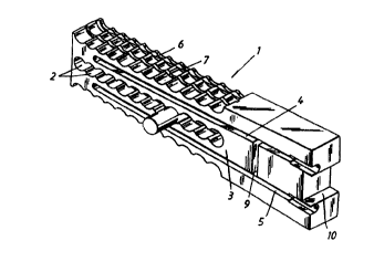
Figure 1 shows an upper stator end plate 1 provided with 10-12
axially running wending slots 2 corresponding to a stator,
arranged radially, the number depending on the design of the
stator, said wind_Lng slots forming a radial chain slot 3. The
CA 02279415 1999-07-23
WO 98/34323 PG"T/SE98/00163
stator end plate is also provided with an inlet slit 4 and an
outlet slit 5 for cooling tubes with flows to and from the
laminated stack. The stator end plate 1 is in the form of a
circle sector with one, two or more chain slots. The sectors
are assembled side by side to form a whole circular plate
covering one end of the stator (the upper end if the axis of
the machine is vertical). The plate 1 is also provided with
two upper casting channels 6, 7 arranged radially in the chain
slot 3 in order to embed an upper sealing member 8 at the exit
of each winding slot 2 from the plate 1 (only one sealing
member is shown in Figure 1). Figure 1 also shows a transverse
slit 9 for cooling tubes running in the stator yoke. A recess
10 is also provided for the fixing bar of the "core".
Figure 2a shows a lower stator end plate 11 which, in
equivalent manner to the upper stator end plate in Figure 1,
is provided with the same number of axially running winding
slots 2 corresponding to the stator as in the upper plate
(10-12), arranged radially and in equivalent manner forming a
radial chain slot 3. The lower stator end plate 11 is provided
with one or more turn-around slits 12 in which cooling tubes
are arranged to run out of the laminated stack, turn and run
into it again. As described for the upper plate, the lower
stator end plate 11 is designed as a circle sector with one,
two or more chain slots. The sectors are assembled side by
side to form a whole circular platy covering one end of the
stator (in this case the lower end if the axis of the machine
is vertical). The stator end plate 11 is also provided with
two lower casting channels 13, 14 arranged radially in the
chain slot 3 in order to embed a lower sealing member 15 at
the exit of each winding slot 2 from the plate 1 (only one
sealing member is shown in this Figure as well). As can be
seen in the Figures, these sealing members may be shaped
differently depending on which plate they belong to. They may
also protrude different lengths from the plate depending on
the protection each member is to provide. The lower stator end
plate 11 is also provided with a recess 10 for the fixing bar
CA 02279415 1999-07-23
WO 98/34323 PCT/SE98/00163
9
of the "core". Figure 2 also shows that the lower stator end
~ plate 11 is provided with a number of attachment holes 16 for
a casting device 100, see Figure 2b, and assembly holes 17 for
~ a locking bolt that locks the plate 11 to a lower thick metal
sheet constituting an annular part of the stator frame.
Figure 2b shows the casting device 100 provided with nipples
110 in the region of the turn-around slits 12. The casting
device 100 is arranged to be connected to the lower stator end
plate 11 by attachment bolts 120. The casting device 100 is
also provided with rubber seals 125 against the end plate, at
silicon embedment of the cooling tubes.
The procedure for embedding the sealing members is for
detachable tools in the form of cylindrical plugs forecasting
the members to be fitted on the end plate and casting compound
injected into a casting inlet in the plate, the compounding
then spreading to all the cable positions.
The procedure for casting cooling tubes is that the casting
device is sealingly connected to a first laminar plate and
silicon is then forced in around the cooling tubes until the
silicon "runs out" at the upper end plate. The casting device
is then removed and attached to another laminar plate and the
injection procedure is repeated, and so on until all cooling
tubes have been embedded in silicon. The cooling tubes are
thus embedded both inside the end plates and inside the
stator. Furthermore, the casting device can be used again.
Two separate casting processes are thus used, one for sealing
members and the other f:or cooling tubes. Different types of
silicon are often used for these processes.
Figure 2c shows a cross section through a high-voltage cable
111 for use in connection with the present invention. The
high-voltage cable 111 is composed of a number of strand parts
112 made of copper (Cu), for instance, and having circular
CA 02279415 1999-07-23
WO 98/34323 PCT/SE98/00163
cross section. These strand parts 112 are arranged in the
middle of the high-voltage cable 111. Around the strand parts
112 is a first semiconducting layer 113. Around the first
semiconducting layer 113 is an insulating layer 114, e.g.
5 XLPE-insulation, and around the insulating layer 114 is a
second semiconducting layer 115. The concept "high-voltage
cable" in the present application thus does not include the
outer sheath that normally surrounds such a cable for power
distribution. The high-voltage cable has a diameter within the
10 interval 20-250 mm and a conducting area within the interval
90-3000 mm2.
Figure 3 shows both casting channels 6, 7 of the upper stator
end plate 1, and a casting inlet 18 for injecting the casting
compound.
Figure 4 shows the upper stator end plate 1 from above, with
an inlet aperture 19 for a cooling tube in the inlet slit 4,
and a first bending member 20 for this cooling tube. Cooling
tube apertures for returning cooling tubes are also shown,
with turning members 23 between them. As indicated in the
Figure, the outlet slit 5 is arranged in corresponding manner,
i.e. with an outlet aperture 24 and corresponding first and
second bending members 20, 23. The inlet and outlet slits 9, 5
are also provided with turned cavities 25 of thicker diameter
on the yoke side of the stator, to~enable connection of the
cooling tube to a thicker tube for extra protection.
In an axial section through the plate, Figure 5 shows a
winding slot 2 and the upper casting channels 6, 7.
In a radial section through the plate, Figure 6 shows the
inlet slit 4 which extends from the inlet aperture 19 to the
turned cavity 25. It can be seen from this Figure that the
first bending member 20 is higher than the second bending
member 23 so that the cooling tube acting as inlet to the
stator is closer to the surface than the cooling tube that
CA 02279415 1999-07-23
WO 98/34323 PCTISE98/00163
11
returns in this plate, i.e. the cooling tubes are situated one
~ above the other in the inlet slit 4.
For the upper stator end plate 1 the plate thickness t", is
S such that t" > 2F,=, where Fr is the external diameter of the
cooling tube so that all cooling tubes are covered by the
plate.
Figure 7 shows the two casting channels 13, 14 of the lower
stator end plate 11, and a casting inlet 18 for injection of
casting compound. What differentiates the lower plate from the
upper plate is that the plate thickness tl is less and that
the casting channels 13, 14 are closer together.
Figure 8 shows the lower stator end plate 11 from its outer
side, revealing its turn-around slits 12, the cooling-tube
apertures 19, 21, 22 and a cooling-tube aperture 26 located in
the stator yoke. .111 these cooling-tube apertures 19, 21, 22,
26 constitute openings in this plate for returning cooling
tubes with third :bending members 27 between them.
In an axial section through the plate in Figure 8, Figure 9
shows a winding slot 2 and the lower casting channels 13, 14.
The section also reveals that the lower plate is provided with
an opening 28 for the casting device.
Figure 10 shows a radial section through the lower stator end
plate 11 and through a lower, thick metal sheet 30 connected
to the plate by a locking bolt 29. The three bending members
27 are also shown recessed in the turn-around slits 12, as
' well as the attachment holes for the casting device. The lower
plate is thus designed for cooling tubes that return inside
' the plate. Since no inlets or outlets are arranged in the
lower plate, the thickness of this plate can be kept to a
minimum. For the stator end plate 11, therefore, the plate
thickness tl is such that t1 > Fr, where Fr is the outer
CA 02279415 1999-07-23
WO 98/34323 PCT/SE98/00163
12
diameter of the cooling.tube, so that all cooling tubes are
covered by the plate.
Figure 11 shows a section through a part of a stator 31
provided with cooling tubes, with its stator core 32, at one
end of which the stator end plate 1 is fitted. It is clear
.from the Figure that all the cooling tubes 33 running in the
inlet and outlet slits are recessed in the stator end plate 1
so that they are protected from mechanical stress. The cooling
tubes 33 are also connected to an inlet circuit 132 for inlet
medium and an outlet circuit 133 for outlet medium.
Figure 12 shows that all cooling tubes are connected to a
closed cooling circuit 129 which, in the embodiment shown,
comprises a tank 30 containing the coolant 131 which may be
water, hydrogen or other coolant. The tank 130 is provided
with a level indicator for controlling and monitoring the
level of the coolant. The tank 130 is also connected to two
annular tubes consisting of the inlet circuit 132 and outlet
circuit 133. Between the inlet circuit 132 and the outlet
circuit 133 a number parallel circuits is connected, the
number often corresponding to the number of stator teeth or
tooth sides provided with cooling tubes, One of these parallel
circuits 134 is shown in Figure 12. The coolant 131 is
arranged to circulate from the inlet circuit 132,
simultaneously through all the parallel circuits 134, to the
outlet circuit 133 and on to a circulation pump 135, to a
circulation filter 136 through a heat-exchanger 137, e.g. a
plate heat-exchanger, and then back to the inlet circuit 132.
Water from a water supply is fed by an exchanger pump 138
through one end of the heat-exchanger 137 via a filter, not
shown. The water is pumped through the exchanger and back to
the water supply.
The stator end plates described are preferably made from
laminated material. They may be in the form of a completely
circular plate instead of being divided into sectors as
CA 02279415 1999-07-23
PG"T/SE98/00163
13 w
described above. Furthermore, all cooling tubes are embedded
in silicon rubber in the stator, in order to improve the heat
transfer between the laminated stack and cooling tubes.
The stator end plate, either upper or lower, has an axial
thickness t such 1=hat t > Fr, where Fr is the outer diameter
of the cooling tube. The designation t may here represent
either tl or tu.
The second and third bending members 23, 27 of the stator end
plates are bent i:n one or two steps, each step constituting an
angle of 90° as shown in Figures 6 and 10, or in one step with
an angle of 180°, i.e. as a semi-circle, if the distance
between the cooling tubes corresponds to the diameter of the
bending circle. T:he first bending member 20 at the inlet
aperture and outlet aperture is bent in one step at an angle
of 90°. The bending members 20, 23, 27 are thus bent in one or
two steps, each step constituting an angle of 90°.