Note: Descriptions are shown in the official language in which they were submitted.
CA 02279443 1999-07-30
Myer 6Z
IHiPROVED PHASE DETECTOR
FIELD OF THE INVENTION
The present invention relates generally to radio frequency (RF) circuitry, and
more particularly to a phase detector for detecting the phase of an input
signal.
BACKGROUND OF THE RELATED ART
A phase detector is a circuit or instrument for detecting a difference in
phase
between corresponding points on two signals. Ordinary phase detectors of radio
frequency
signals at 2 GHz use a miner as a phase detector. FIG. 1 illustrates such a
phase detector 10
comprising amplitude limiters 12, 14 and a miner 16. Signals S, and Sd are
provided as inputs to
amplitude limiters 12, 14, respectively. For purposes of illustration, signal
S, is a 1.999 GHz
signal and Sb is a 2.000 GHz signal. Amplitude limiters 12, 14 saturate the
amplitudes of signals
S, and Sb to produce output signals S,i and S14, thereby eliminating amplitude
variations between
signals S, and Sb. Note that signals S,Z and S" are signals representative of
signals S, and Sb,
respectively. Signals S,2 and S,4 are mixed by miner 16 to produce output
signal S,6. Since
signals S,2 and S" have 360° of phase shift between them (i.e., S, is
1.999 GHz and Sb is 2.000
GHz), mixer 16 will produce a sine wave output signal (i.e., signal S,6 is a
sine wave output
signal). See Fig. 2, which depicts a sine wave output signal 20.
Using the phase detector 10 of FIG. 1 (and other similar phase detectors) in a
feedback system to control the phase of one or more signals has certain
limitations. Particularly,
the feedback system would be limited to detecting phase differences of
i90° because of direction
reversal by signal S,6. For example, if signals S, and Sb have a phase
difference of +45°
(indicated by point A), a voltage value of 0.5 is indicated. The +45°
phase difference is indicated
by point A on FIG. 2. At 90°, the direction of signal S,6 reverses and
at a +135° phase difference
between sigoala S, and Sd (indicated by point B), a voltage value of 0.5 is
also indicated. Thus,
the prior art phase ddector 10 uses the same voltage value to indicate
different phase differences.
This, in effect, limits the range of phase detector 10 (and the feedback
system) to t90°.
In some instances, a feedback system incorporating the phase detector 10 of
FIG.
1 (and other similar phase detectors) is sufficient for detecting phase
differences between two
signals if the phase differences should be within t90°. However, in
instances where the phase
differences between two signals to be phase detected will be beyond
t90°, e.g., 135°, such phase
CA 02279443 2001-09-28
2
detector 10 (or equivalents) will be inadequate since a same voltage value may
indicate
multiple phase differences. The ideal phase detector should be monotonic for
measuring
phase differences within a range of ~ 180°. That is, the ideal phase
detector should indicate
an absolute voltage value for each phase difference between ~ 180°.
Accordingly, there
exists a need for such a phase detector.
SUMMARY OF THE PRESENT INVENTION
The present invention is a method and an apparatus for measuring phase
differences between signals A and B using an absolute voltage value for each
phase
difference between ~ 180°. The present invention uses a third signal C
derived from
summing approximately equal amplitude signals representative of signals A and
B. Thus,
signal C is a signal having a phase approximately equal to the average phase
between
signals A and B. In one embodiment, signals C and A are subsequently amplitude
limited
and mixed to produce a fourth signal D, which is a signal having associated an
absolute
voltage value for each degree of phase difference between ~ 180° for
signals A and B.
In accordance with one aspect of the present invention there is provided a
method of detecting a phase relationship between two signals comprising the
steps of:
splitting a first input signal to produce a first split signal having an
amplitude and a second
split signal having an amplitude; adjusting the amplitude of the first split
signal to produce a
first amplitude adjusted split signal having an amplitude; adjusting the
amplitude of the
second split signal to produce a second amplitude adjusted split signal having
an amplitude;
summing a second input signal having an amplitude and the second amplitude
adjusted split
signal to produce a summed signal having an amplitude, the amplitude of the
second
amplitude adjusted split signal being approximately equal to the amplitude of
the second
input signal; adjusting the amplitude of the summed signal to produce an
amplitude adjusted
summed signal having an amplitude approximately equal to the amplitude of the
first
amplitude adjusted split signal; and mixing the first amplitude adjusted split
signal with the
amplitude adjusted summed signal to produce a mixed signal.
In accordance with another aspect of the present invention there is provided
a phase detector comprising: a splitter for splitting a first input signal
into a first split signal
having an amplitude and a second split signal having an amplitude; a first
amplitude limiter
for saturating the amplitude of the first split signal to produce a first
amplitude adjusted split
signal; an attenuator for adjusting the amplitude of the second split signal
to produce a
CA 02279443 2001-09-28
2a
second amplitude adjusted split signal having an amplitude; a summer for
summing the
second amplitude adjusted split signal and a second input signal to produce a
summed
signal having an amplitude; a second amplitude limner for saturating the
amplitude of the
summed signal to produce an amplitude adjusted summed signal, the first and
second
amplitude limner having an approximate identical boundary value; and a mixer
for mixing
the amplitude adjusted summed signal with the first amplitude adjusted split
signal.
BRIEF DESCRIPTION OF THE DRAWINGS
The features, aspects, and advantages of the present invention will become
better understood with regard to the following description, appended claims,
and
accompanying drawings where:
FIG. 1 depicts a block diagram of a phase detector in the prior art;
FIG. 2 depicts a waveform of an output signal of the phase detector of FIG. 1
when
the frequency of the input signals are 1.999 GHz and 2.000 GHz;
FIG. 3 depicts a block diagram of an improved phase detector in accordance
with
one embodiment of the present invention;
FIG. 4 depicts a vector diagram for signals S36 and S3g and a vector diagram
for
resultant signal S4o;
FIG. 5 depicts a waveform for an output signal of the phase detector in
accordance
with one embodiment of the present invention when the frequency of the input
signals are
1.999 GHz and 2.000 GHz; and
FIGS. 6 and 7 depict phase detectors in accordance with other embodiments of
the
present invention.
CA 02279443 1999-07-30
Myer 62
DETAILED DESCRIPTION
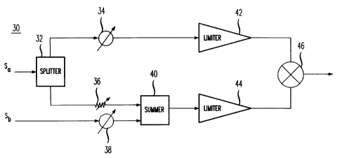
FIG. 3 depicts an improved phase detector 30 in accordance with one
embodiment of the present invention. The phase detector 30 comprises sputter
(or directional
coupler) 32, phase shifters 34, 38, an attenuator 36, summer 40, amplitude
limiters 42, 44 and a
mixer 46. Signals S, and Sd are provided as inputs to sputter 32 and phase
adjuster 38,
respectively. Sputters, phase shifters, attenuators, summers, amplitude
umiters and mixers are all
well-lmown in the art. For purposes of illustration, signal S, is a 1.999 GHz
signal and Sb is a
2.000 GHz signal. This should not, however, be construed to limit the present
invention in any
manner.
Sputter produces and directs sisals S3z_1 and S3z_z to phase adjustez 34 and
attenuator 36, respectively. For purposes of this application, the term
sputter and directional
coupler (along with their functionality) shall be construed to be
interchangeable with each other.
Signals S3z_, and Sb are phase shifted by phase adjusters 34 and 38 to produce
output signals S~,
and S38, which are phase shifted signals representative of signals S, and S~,
respectively. Signals
S~, and S3a should have approximately identical phases. Signals S3z_, and Sd
are phase shifted for
purposes of producing an absolute voltage relationship corresponding to the
phase relationship
between signals S, and Sb. For example, phase adjusters 34 and 38 are used to
set an absolute
2o voltage of 0 volts in order to indicate a 0° phase difference
between signals S, and Se. Note that if
an absolute voltage relationship need not be shown between signals S, and Ss,
then phase
adjusters 34 and 38 are not required.
The amplitude of signal S3z_z is adjusted by attenuator 36 to produce signal
S3~,
which is an attenuated (or amplitude adjusted) signal representative of signal
S3z_z. Signal S3z_z is
attenuated such that signal S36 has approximately the same amplitude as signal
Sd. Signals S36
and S3a are provided as inputs to summer 40 to produce resultant signal S,o,
which is a signal
having a phase approximately equal to the average phase of signals S36 and
S38. If the amplitude
of sisal S~.z was not attaruated such that signal S36 has approximately the
same amplitude as
signal S3a, the phase of resultant signal S,~ would more closely approximate
the phase of
whichever signal (i.e., S36 or S38) has the larger (absolute) amplitude. In an
alternate embodiment,
signal S3a (or Sb) can be attenuated to match the amplitude of signal S3z_z.
FIG. 4 depicts a vector diagram 50 for syoals S36 and S3a and a vector diagram
52 for resultant signal S,~ (represented by a plurality of dashed vectors
con~espoading to the phase
relationship between signals S36 and S3a). At 1180° phase difference
between signals S36 and S3a,
CA 02279443 1999-07-30
Myer 61
4
the phase of signals S,o is null. As the phase of signal S38 shifts clockwise
with r~p~ to signal
S3~, the phase of signal S,~ shif3s from -180° to +180°. Note
that at +180°, the phase of signal S,~
jumps to -180°.
The amplitudes of signals S~, and S,~ are saturated by amplitude limiters 42
and
44 to produce signals S42 and S,,,, which are amplitude limited signals
representative of signals
S~ and S,~, respectively. Amplitude limiters 42 and 44 should have
approximately the same
boundary value such that the amplitude variations in signals S~, and S,~ may
be eliminated,
thereby leaving only the phase information in output signals S42 and S"..
Signal S,4 is mined with signal S,2 by miner 46 to produce resultant signal
S,6,
which is a signal indicative of the phase relationship between signals S, and
Sd. For each phase
relationship between 1180°, signal S,6 has associated an absolute
voltage value. Unlike prior art
phase detectors where a voltage value may indicate two phase relationships,
the present invention
phase detector is monotonic - that is, a voltage value may indicate only one
phase relationships
between 1180°.
FIG. 5 depicts a waveform 52 for signal S,~ when signal S, is a 1.999 GHz
signal
and Sb is a 2.000 GHz signal. Waveform 52 (or signal S,~) curves upward from -
180° to +180°.
Each degree of the phase relationship between signals S, and Se is associated
with an absolute
voltage value. Preferably, phase adjusters 34 and 38 are set to shi8 the
phases for signals S, (or
S32-1) ~d Sb such that signal S,~ has a zero voltage value when signals S, and
Se are in-phase (i.e.,
0° phase difference). Note that at +180°, the waveform for
signal S,~ flips to -180° and starts
curving upwards again. Thus, no single voltage value will indicate multiple
phase relationships
between signals S, and Sd.
Although the present invention has been described in considerable detail with
reference to certain embodiments, other versions are possible. For example,
see FIGS. 6 and 7.
As shown in FIG. 6, the signals S36 and S3a are amplitude limited (to the same
amplitude) before
being provided as inputs to summer 40. As shown in FIG. 7, signal S38 is
amplitude limited and
signal S,~ is split by a sputter (before being provided to summer 40).
Therefore, the spirit and
scope of the preaeat invention should not be limited to the description of the
embodiments
contained herein.