Note: Descriptions are shown in the official language in which they were submitted.
CA 02279733 1999-08-05
1
BRACKET HAVING INTEGRAL LOCATING BEACON
BACKGROUND OF THE INVENTION
1. FIELD OF THE INVENTION
The present invention relates to an improvement to
brackets, the improvement comprising incorporation of a
signalling beacon. The beacon visually or audibly
indicates location of the bracket. A particularly
critical application of the invention is to signal the
location of a fire extinguisher in a room or corridor of
a building which has been darkened by intentional or
damage responsive interruption of lighting.
2. DESCRIPTION OF THE PRIOR ART .
Certain objects are intended for emergency use, and
locating the same during an emergency is of the essence.
An example is a fire extinguisher. Fire extinguishers
are generally mounted to environmental surfaces, such as
building walls or walls of a motor vehicle. In the event
of a fire or similar emergency situation calling for
utilization of the fire extinguisher, the mere act of
locating the fire extinguisher may present a problem. It
may be that in the event of a fire, smoke obscures the
location of the fire extinguisher. Alternatively,
CA 02279733 1999-08-05
2
lighting within a building or motor vehicle may be
interrupted either intentionally to mitigate propensity
for damage or in response to damage which has already
occurred.
Any of these situations may render a fire
extinguisher difficult to locate in the moment of need.
Yet at this time, it is most critical that the fire
extinguisher be conspicuous. There remains a need for
ability of a fire extinguisher to remain conspicuous in
conditions of poor illumination within a structure.
United States Patent Number 4,787,460, issued to
Joseph G. Clarkson on November 29, 1988, further
describes the problem and proposes a visual solution for
the problem. The solution proposed by Clarkson takes the
form of a covering or mounting plate for a fire
extinguisher mounted in a building which is brightly
marked in distinctive patterns for making the mounting of
the fire extinguish conspicuous. However, under
conditions wherein ambient illumination is very weak or
absent, even the bright and distinctive markings of
Clarkson are susceptible to being rendered ineffectively
conspicuous. By contrast, the present invention provides
a self-illuminated bracket, which generates its own
illumination, thereby overcoming inadequate ambient
lighting.
CA 02279733 1999-08-05
3
A bracket for a fire extinguisher is shown in United
States Design Patent Number 244,392, issued to Roger Jay
Montambo on May 17, 1977. This device is representative
of fire extinguisher brackets generally, showing critical
characteristics thereof, and lacks lighting of any type.
A bracket having an associated light is shown in
United States Design Patent Number 266,061, issued to
Karl H. Wenzlaff on September 7, 1982. However, unlike
the present invention, Wenzlaff's bracket is intended to
support the light and not a second object, such as a fire
extinguisher.
United States Patent Numbers 5,408,771, issued to
Bob Manrubia on April 25, 1995, and 5,412,887, issued to
James R. Layne on May 9, 1995, describe, respectively, an
illuminated box frame and an illuminated cabinet. In
both cases, the subject invention nearly fully envelopes
the enclosed object. By contrast, the present invention
is a bracket having a limited number of bands engaging
the enclosed object along a limited area of its outer
surface. This characteristic exposes a significant
portion of the supported object, which has the effect of
suggesting or revealing how to disengage the object from
its support. This is important in the case of fire
extinguishers, which may well be required to be deployed
expeditiously when their necessity arises.
_, _
CA 02279733 1999-08-05
4
None of the above inventions and patents, taken
either singly or in combination, is seen to describe the
instant invention as claimed.
SUMMARY OF THE INVENTION
The present invention combines a suitable,
conventional mounting for a fire extinguisher with a
self-contained beacon for rendering the fire extinguisher
conspicuous. The beacon may be audible, visual, or both.
The mounting for the fire extinguisher has structure for
engaging the fire extinguisher and structure for mounting
the bracket to an environmental surface.
Preferably, the bracket incorporates conventional
structural features for engaging the fire extinguisher,
such as a band for encircling a cylindrical fire
extinguisher. Structure for mounting the bracket to an
environmental surface may include a plate having holes
for receiving fasteners, for wall mounting. Recessed
mounting may be accommodated by providing a frame
suitable for mounting in a recess in a wall. Still other
mounting structure is possible, such as a floor stand.
The beacon is preferably provided with independent
power, such as batteries carried on board the novel
bracket. This renders illumination independent of any
power connection to a building, which power connection is
CA 02279733 1999-08-05
susceptible to interruption during a fire. Controls are
optionally provided for deenergizing or otherwise
regulating the beacon. The beacon may be turned on,
turned off, and connected to a secondary controller which
5 responds to certain conditions. An example of the latter
is a proximity detector, which links beacon operation to
inference of human activity. Since most human activities
involve motion, the beacon could be operative only when
human presence is inferred, so as to conserve battery
power and avoid interruption of operation for service.
A second example is a proximity switch energizing
the beacon when the fire extinguisher is supported by the
bracket. This feature avoids battery depletion when the
fire extinguisher is removed for use, service, transport,
or instruction of personnel.
Accordingly, it is a principal object of the
invention to provide a bracket for supporting a fire
extinguisher, the bracket having a beacon for rendering
the fire extinguisher conspicuous.
It is another object of the invention to provide
power for the beacon which renders the novel bracket
independent of connection to power from an external
structure.
It is a further object of the invention to provide a
self-illuminating visual beacon.
CA 02279733 1999-08-05
6
Still another object of the invention is to provide
an audible beacon.
An additional object of the invention is to provide
controls for deenergizing the beacon when desired.
It is again an object of the invention to conserve
power of the power supply of the novel bracket, thereby
extending a period of service during which the power
supply need not be replenished or otherwise serviced.
Yet another object of the invention is to link
beacon operation to inference that human activity is
present.
It is an object of the invention to provide improved
elements and arrangements thereof in an apparatus for the
purposes described which is inexpensive, dependable and
fully effective in accomplishing its intended purposes.
These and other objects of the present invention
will become readily apparent upon further review of the
following specification and drawings.
CA 02279733 1999-08-05
7
BRIEF DESCRIPTION OF THE DRAWINGS
Various other objects, features, and attendant
advantages of the present invention will become more
fully appreciated as the same becomes better understood
when considered in conjunction with the accompanying
drawings, in which like reference characters designate
the same or similar parts throughout the several views,
and wherein:
Fig. 1 is a front perspective view of a first
embodiment of the invention.
Fig. 2 is a perspective view of a second embodiment
of the invention.
Fig. 3 is a perspective view of a third embodiment
of the invention.
Fig. 4 is an electrical schematic of the power
circuit of a further embodiment of the invention.
Fig. 5 is a diagrammatic detail view of an
alternative form of a switch employed in the circuit of
Fig. 4.
CA 02279733 1999-08-05
8
DETAILED DESCRIPTION OF THE PREFERRED EMBODIMENTS
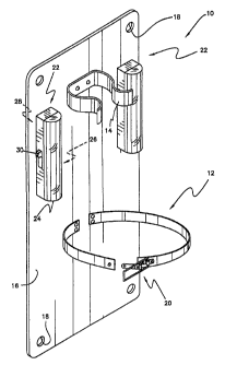
Turning now to Fig. 1 of the drawings, bracket 10 is
seen to comprise a band 12 and a clip 14 fixed to a base
plate 16. Base plate 16 has holes 18 for accepting
fasteners (not shown) enabling bracket 10 to be mounted
to a vertical environmental surface. Band 12 encircles
and thus partially surrounds an elongated object (not
shown) which is to be supported by bracket 10. Band 12
has a suitable latch 20 for securing the supported object
to bracket 10.
Components described thus far are generally
conventional. Bracket 10 is distinguished from prior art
brackets by provision of two visible beacons in the form
of lighting fixtures 22. Each lighting fixture 22 has a
lens 24, a lamp 26, a battery 28, and a switch 30. Each
lighting fixture is thus self-contained, and independent
of connection to external power.
The two lighting fixtures 22 are provided so that
when a fire extinguisher or other elongated object is
secured to bracket 10, light emanating from one lighting
fixture 22 will be visible from every viewing direction.
That is, the fire extinguisher will not conceal all
light, as might occur if only one lighting fixture 22
were provided.
CA 02279733 1999-08-05
9
The embodiment of Fig. 1 is intended for mounting on
a wall of a room or corridor of a building or a mobile
structure, such as a motor vehicle. A second embodiment
is shown in Fig. 2. Bracket 30 is intended for flush
mounting in a wall or other vertical environmental
surface. To this end, bracket 30 has a recessed cabinet
32 and a trim flange or plaster ring 34. Cabinet 32 is
intended to occupy a cavity formed in the wall, and is
inserted into the cavity during installation until
plaster ring 34 abuts the wall.
Cabinet 32 is preferably of a depth sufficient so
that a fire extinguisher may be housed therein and not
project forwardly of plaster ring 34. Optionally, a door
(not shown) or other closure may be hinged to or
otherwise fastened to cabinet 32.
Bracket 30 has a band 36 and a clip 38 mounted on
the rear wall 40 of bracket 30. Band 36 and clip 38 are
essentially similar to those of the embodiment of Fig. 1.
Because bracket 30 is flush mounted, the fire
extinguisher will not obscure beacons provided to render
bracket 30, and thus the fire extinguisher, conspicuous.
Therefore, beacons need not be duplicated, as is the case
with the embodiment of Fig. 1.
CA 02279733 1999-08-05
Bracket 30 has a visible beacon 42, which may be
substantially identical to lighting fixture 22 of Fig. 1,
and therefore will not be described further. Bracket 30
also has an audible beacon in the form of buzzer or chime
5 44. Chime 44 has a battery and switch (neither shown),
but differs from lighting fixture 22 in having an
integral sound generator. Both visible beacon 42 and
chime 44 are provided so that in the event of a fire,
location of the fire extinguisher will be apparent to all
10 occupants, sighted or blind, and with or without ambient
lighting being present in the structure having bracket
30.
Referring now to Fig. 3, bracket 50 supports a fire
extinguisher in an upright orientation in a manner
similar to those of brackets 10 and 30. However, bracket
50 is adapted to be mounted on a horizontal surface such
as a countertop, floor, or upper surface of a table.
Bracket 50 includes a base plate 52, a band 54 for
securing the fire extinguisher, and holes 56 for
accepting fasteners. Band 54 is fixed to base plate 52
so that the fire extinguisher will be vertically oriented
when base plate 52 occupies a horizontal plane. A
lighting fixture 58 is mounted to base plate 52, and
serves as a source of visible light. Lighting fixture 58
has battery, switch, and lamp which are essentially
CA 02279733 1999-08-05
11
similar to those of lighting fixture 22 of Fig. 1.
However, lighting fixture 58 is conf~gured and located to
be visible even when a fire extinguisher is in place,
supported by bracket 50.
Fig. 4 illustrates an electrical power circuit
serving beacons provided for a bracket provided with one
or more beacons. The circuit includes a battery 60, a
visible beacon 62, and audible beacon 64, a manual switch
66, and an automatic switch 68. Visible beacon 62 is any
suitable lighting fixture. Optionally, beacon 62
includes a flasher 70. Flasher 70 is any suitable device
for periodically interrupting power to beacon 62, with
the result that beacon 62 flashes or illuminates
intermittently. If desired, audible beacon 64, which may
be any suitable buzzer or chime, may also be provided
with a device interrupting power periodically so that
beacon 64 operates intermittently.
Switch 66 provides three switching conditions
affording control over the mode of operation of beacons
62, 64. In one condition, that corresponding to a
position of a dial or operating lever shown at 72, power
to beacons 62, 64 is disconnected from battery 60. A
representative operating lever is shown in solid lines in
position 72 in the depiction of Fig. 4.
CA 02279733 1999-08-05
12
The operating lever may also be moved to a second
position indicated in broken lines at 74. In this
position, the switch will connect power from battery 60
to beacons 62, 64, so that beacons 62, 64 are operating.
In the third condition, indicated in broken lines at 76,
power is connected to beacons 62, 64 through automatic
switch 68. Beacons 62, 64 thus operate responsively to a
condition actuating switch 68.
Automatic switch 68 responds to a condition which a
user may wish to monitor in order to cause beacons 62, 64
to operate. In the example of Fig. 4, switch 68 is a
proximity switch having a plunger 78. Switch 68 is
physically located in an appropriate place on a bracket
10, 30, or 50 so that placement of a fire extinguisher in
the intended position for storage causes the fire
extinguisher to contact and deflect plunger 78.
Deflection of plunger 78 closes the circuit, and beacons
62, 64 operate. Therefore, operation of beacons 62, 64
is limited to times when a fire extinguisher is actually
placed in and supported by bracket 10, 30, or 50. At
other times, power of battery 60 is conserved. Also, no
sound or light are generated which could potentially
distract persons present and engaged in various
activities.
CA 02279733 1999-08-05
13
Other conditions may be monitored to effect
operation of beacons 62, 64. As seen in Fig. 5, an
automatic switch 80 comprises a motion detector 82.
Motion detector 82 has associated contacts 84 closing a
circuit when motion is detected. In a building, it is a
reasonable assumption that people are frequently moving,
and that human presence may be inferred by detection of
motion. This arrangement assures that beacons 62, 64 are
operative when persons are present, and that battery
power is conserved when no occupants are present.
Other arrangements of brackets 10, 30, and 50, and
associated power circuits are possible. More than one
type of automatic switch may be provided. For example,
an additional automatic switch incorporating a light
detector may be employed to operate beacon 62 when
ambient light falls below a predetermined threshold.
An automatic switch may be bypassed in connecting a
beacon 62 or 64. For example, audible beacon 64 may be
arranged to operate regardless of detection of light.
The number, nature, and location of beacons may be
varied to suit preferences. Control of beacons may also
be varied.
Thus there has been described a bracket primarily
although not necessarily devoted to a fire extinguisher,
the bracket being improved by beacons signalling the
CA 02279733 1999-08-05
14
location of the bracket and hence of a fire extinguisher.
The bracket is distinguished from other supports by the
characteristic that it includes structure for supporting
an elongated object in a substantially fixed position
relative to the bracket by partial encirclement or
surrounding. If the band or equivalent structure for
engaging the object is elastic or deformable, some
incidental movement of the object may occur.
This structure is unlike a support structure such as
a cabinet having shelves, which do not engage secured
objects by partial encirclement or surrounding, and thus
do not secure their supported objects in a substantially
fixed position. Also, a bracket secures its subject
object in a location substantially centered relative to
the bracket. If the bracket is modified to support.
plural objects, then the plural objects, when all are
present and supported, will collectively be centered
relative to the bracket.
It is to be understood that the present invention is
not limited to the embodiments described above, but
encompasses any and all embodiments within the scope of
the following claims.