Note: Descriptions are shown in the official language in which they were submitted.
CA 02280265 1999-08-09
WO 98/34734 PCT/CA98/00097
-1-
PAINTING METHOD AND APPARATUS FOR SPRAY PAINTING Of VERTICAL SURFACES
FIELD OF THE INVENTION
This inventioin relates to a method and apparatus for spray
painting generally vertical surfaces such as the surface of a screen on
which a motion picture is to be projected.
BACKGROUND OF THE INVENTION
In the field of high-quality motion picture projection systems
such as those available from Imax Corporation, great emphasis is placed
on image brightness. One factor in achieving high levels of image
brightness is the reflective characteristics of the screen on which images
are projected. Special so-called "high gain" reflective paints have been
developed that are applied to the image receiving surface of the screen. In
the case of 3-D projiection systems in which the projected light is polarized,
the paint also has t:he effect of preserving linear polarization of the light.
At least in the case of screens other than domed screens, the
paint typically is applied to the screen using a spray gun as the screen is
erected in a theatre. A single coat of paint is applied to the front surface
of
the screen by moving the gun across the screen as it is withdrawn
upwardly from a housing on the floor of the theatre.
The piresent inventors have recognized that it is important to
maintain a constan1t paint spray fan width as the paint contacts the screen,
over the entire screen surface. If the width of the spray changes due to
bulges in the screen (in o:r out), the same thickness of paint may not be
applied to all areas of the screen. This affects the appearance of the screen
and can lead to visiible vertical stripes. In addition, a narrower paint spray
would have a grea.ter concentration of paint than a wider area, and vice
versa; this will affect the drying time of the paint which can exacerbate the
appearance of stripes.
So far as is kilown, the prior art fails to provide a solution to
this problem. It has been proposed to use mechanical sensors to space a
spray gun from a surface to receive paint. For example, United States
CA 02280265 1999-08-09
-2-
Patent No. 4,296,317 (Kraus) shows a sprav gun ivhich is fitted with a wheel
adjacent the gun nozzle for maintaining a constant distance between the
paint gun nozzle and the surface of a work piece to be painted. United
States Patent No. 4,108,105 (Wiggins) discloses a paint spray system in
which a mechanical sensor is used to determine the width of a workpiece
and then control the distance of the paint nozzles from the workpiece.
However, mechanical sensors that contact the surface to be painted are not
acceptable in the case of r.notion picture screens because of the risk of
marking or otherwise damaging the screen.
Ultrasonic sensors are disclosed in U.S. Patent No. 4,501,223
(Matsuno, et al.) in the context of an apparatus for use in painting a ship.
A pair of sensors are arranged in vertically spaced positions on a support
assembly that is pivotally rrtounted for movement towards and away from
the surface to be painted. A paint spray head is vertically movable on the
support assembly. The upper or lower sensor controls the tilt of the
support assembly depending on whether the spray head is above or below
the pivot point of the support assembly.
Examp].es of other prior art patents of which applicant is
aware are United States Patents Nos. 4,278,046 (Clarke et al.) and 5,203,923
(Hartman).
An object of the present invention is to provide a painting
method and apparatus which is designed to permit the application of
substantially uniforrn paint coatings to motion picture projection screens
and other vertical surfaces.
SUMMARY OF THE INVENTION
According to the invention there is provided an apparatus for
painting a generally upright surface having an X dimension and a Y
dimension which are mutually perpendicular (e.g. horizontal and
vertical). An elongate support member extends across the surface in the Y
direction (e.g. vertically) and generally parallel to and spaced from the
surface. Carried by the support member is means for indexing the support
member across the surface in the other direction (e.g. horizontally)
AMENDED SHEET,
CA 02280265 1999-08-09
-3-
through a plurality of mutually parallel positions. A carriage is coupled to
the support member for movement along the member and across the
surface in the first d.irection.. A paint spray head is provided for
delivering
paint to the surface and is supported on the carriage by means permitting
movement of the sp:ray head (1) towards and away from the surface and (2)
in the first directiori with respect to the carriage (e.g. vertically) between
respective end positions for painting respectively opposite marginal
portions of the surface (e.g. the top and bottom). A first actuator is coupled
between the carriage and the spray head supporting means for controlling
the movement (1) of the spray head towards and away from the surface.
Non-contact sensor means is carried by the spray head for sensing the
distance between the spray head and the surface by directing a sensing
beam onto the surface and producing data representing the distance.
Means is provided fiDr controlling the actuator in accordance with the data
to maintain the distance at least substantially constant. A second actuator
is coupled between the spray head supporting means and the spray head
for controlling the movement (2) of the spray head in the first direction
with respect to the carriage., Coupled to the second actuator is means for
controlling that actuator so that the spray head moves between its
respective end positions as the carriage moves across the surface in the
said first direction.
The invention permits maintenance of a constant paint spray
fan width as the paint contacts the surface (e.g. a movie screen) over the
entire surface of the screen even where bulges or other imperfections in
the screen are encourttered. The spray head moves in or out automatically
in response to in or out bulges in the screen, maintaining a constant spray
fan width, and assur:ing uniform painting of the entire screen area. At the
same time, there is no physical contact with the screen surface which could
result in marks or other darnage that might be visible when the screen is
in use. Multiple coats of paiiit may be applied.
Space limitations often are of major concern in a motion
picture theatre, particularly where the screen is to be used for projecting
AMENDED SHEtT
CA 02280265 1999-08-09
-4-
large format images such as those that are produced using IMAXT"
projection systems. Typically, the screen will fill substantially the entire
available space in i:he theatre. As such, it is important that the screen
painting apparatus (paint rig) be as compact as possible. The described
feature of differential movement between the spray head and the carriage
allows that objective to be accomplished at least in the vertical direction.
Also for reasons of compactness, the support member preferably extends in
the vertical direction. While it would be possible to have the support
member extend horizontally, this would require tracks or other support
structure at the sides of the screen, where space generally is not available.
However, this may not be a concern in other applications or where small
screens are being pamted.
In order to take account of space limitations laterally of the
screen when the support rnember extends vertically, provision preferably
is made for the paint gun to be positioned in either of two alternative
locations on opposite sides of the support member (or "tower") and to be
AMEVGED'
v=~G = ~
CA 02280265 1999-08-09
WO 98/34734 PCT/CA98/00097
-5-
interchangeable between those two positions, i.e. to the left side of the
tower for painting the left--hand edge of the screen and to the right side of
the tower for paintiing the :right edge.
BRIEF DESCRIPTION OF ,THE DRAWINGS
In order that the invention may be more clearly understood,
reference will now be inade to the accompanying drawings which
illustrate a particular preferred embodiment of the invention by way of
example, and in which:
Fig. 1. is an overall perspective view of a paint rig in
accordance with th.e invention shown in association with a motion picture
projection screen to be painted;
Fig. 2 is a diagrammatic plan view of the paint spray head of
the rig;
Fig. 3 is a perspective view of part of the tower of the rig
showing a primary carriage that is movable vertically on the tower;
Fig. 4 is a perspective view of the carriage and an associated
secondary carriage (which carries the paint spray head); and,
Fig. 5 is a schematic illustration of the overall control system
for the paint spray head.
DESCRIPTION OF PREFERRED EMBODIMENTS
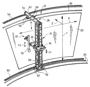
Refer:ring first to Fig. 1, a projection screen for a motion
picture theatre is generally indicated by reference numeral 20. In this
embodiment, the screen is made of a vinyl material and is tensioned
between upper and lower supports, which have not been shown since the
screen structure itself is known. The screen has horizontal and vertical
dimensions which are generally indicated at X and Y. Typically, the screen
will not in fact be truly rectangular and is not shown as such. This is
necessary in order to accommodate image configuration as determined by
the theatre design and projector characteristics. The screen may also be
slightly convexly curved as seen in plan.
A rig for applying paint to the front surface of the screen is
generally denoteci by reference numeral 22 and includes an upright
CA 02280265 1999-08-09
WO 98/34734 PCT/CA98/00097
-6-
support member or tower 24 that extends in the vertical (Y) direction of
the screen over slightly more than the total screen height. Tower 24
extends parallel to and is spaced outwardly from the front surface of the
screen. The tower is supported at its lower end on a removable track 26
having a general configuration that follows the curvature of the screen.
At its upper end, the tower is carried by a frame or bracket 28 from a
further track 30 that is permanently installed in the theatre above the
screen, again generally in a configuration that follows the screen
curvature.
A paint spray head generally indicated at 32 is carried from
tower 24 by carriages 34 and 36 (shown only schematically in Fig. 1) so that
the head 32 can be moved up and down the tower for applying "bands" of
paint to the screen in the vertical direction. The tower can also be indexed
to successive laterally spaced positions on the two tracks 26 and 30 so that
the vertical bands of paint can be applied over the lateral extent of the
screen.
The paint spray head is shown somewhat diagrammatically
in Fig. 2 and, in essence, comprises a paint spray gun having a nozzle 38,
and a support 40 that also carries two ultrasonic sensors 42 and 44 on
respectively opposite sides of the spray gun.
The two carriages that support the spray head 32 on the tower
24 may be regarded as a primary carriage 34 and a secondary carriage 36.
The two carriages are shown in detail in 'Fig. 4. The primary carriage is
movable vertically up and down tower 24 in a direction which is indicated
by the arrow Yl in Fig. 1. The secondary carriage 36 is coupled to carriage
34 so that it can move towards and away from the screen in a direction
denoted 2 to vary the distance between the spray head 32 and the screen
surface. In addition, the spray head 32 can move up and down on the
secondary carriage 36 in a direction which is denoted Y2 in Fig. 1. As will
be described in more detail later, the paint rig is operated so that the spray
head is initially disposed towards the lower end of carriage 36 for painting
the bottom edge of the screen. As the primary carriage 34 moves up tower
CA 02280265 1999-08-09
WO 98/34734 PCT/CA98/00097
-7-
24, spray head 32 is progressively moved up on carriage 36 (in the Y2
direction) so that lDy the t:ime the primary carriage reaches the top of the
tower, the spray head 32 is at the top of the secondary carriage, for painting
the top edge of the screen. This allows the overall height of the paint rig to
be kept to a minintum due to space constraints within a typical theatre, as
discussed previously.
It will. be seeri that the paint spray head 32 is shown at the left-
hand side of the primary carriage 34 as drawn in Fig. 1. This is the position
of the spray head for painting the left-hand edge of the screen. The rig is
designed so that, xAihen toiNer 24 is traversed to the right, the spray head
32
can be moved to the right hand side of the primary carriage 34 ("gun
swap") for painting the right hand side of the screen. Again, this feature is
provided in order to take account of space limitations at opposite sides of
the screen.
Reference will now be made to Figs. 3 and 4 in describing the
structure of the paint rig in more detail. Fig. 3 shows a section of the
vertical tower 24 with the primary carriage 34 mounted on the tower. It
will be seen that the tower is essentially an elongate rectangular box of
"open" space franie construction. The primary carriage is a rectangular
frame that is designed to surround the tower. A series of wheels 46 on
carriage 34 run on the corners of the tower. An electric motor 47 on
carriage 34 drives a toothed wheel 48 that engages a toothed belt 50
extending from top to bottom of the 'tower, for driving the carriage
vertically along the tower. Belt 50 is not shown in Fig. 1. Fig. 1 does,
however, show that a similar belt drive arrangement is provided for
traversing the tower in the horizontal (X) direction. Frame 28 at the top of
the tower carries a motor 52 which drives a toothed wheel 54 in
engagement with a belt 56 that is installed parallel to the upper track 30.
Wheels on brackel: 28 that run on track 30 are shown diagrammatically at
56. Similarly, a rnotor 57' at the lower end of the tower drives a toothed
wheel 58 in engagement with a toothed belt 60 that extends parallel to
track 26. Wheels supporting the bottom of the tower are indicated at 62.
CA 02280265 1999-08-09
WO 98/34734 PCT/CA98/00097
-8-
In Fig. 4, the primary carriage 34 is shown generally as seen in
the direction of arrow A in Fig. 1 (looking outwardly from the screen to
the right of the tower). It will be seen that the secondary carriage 36 is
essentially a rectangular frame that extends around the primary carriage 34
and is elongated somewhat in the Z direction so as to permit adjustability
of the secondary carriage 36 with respect tb the primary carriage 34 in that
direction. Pairs of linear bearings (two of which are visible) are provided
on respectively opposite sides of the primary carriage 34 for supporting the
secondary carriage. The visible pairs of bearings are indicated at 64 in Fig.
4.
Mounted on one side of the primary carriage 34 below the
secondary carriage 36 is a horizontal linear actuator 66 that is coupled to
the secondary carriage 36 at 68, for effecting movement of the secondary
carriage with respect to the primary carriage in the Z direction. Actuator 66
includes a motor 70 which is controlled in accordance with data generated
by the two ultrasonic sensors 42 and 44 (Fig. 2) to position the secondary
carriage 36 in the Z direction so as to maintain constant the distance
between the paint spray gun 38 and the screen 20.
The two sensors 42 and 44 and the spray head 32 are shown in
Fig. 5. The sensors provide signals to a signal evaluator 72 which averages
the two signals and provides an analog signal to a programmable logic
controller (PLC) 74, which in turn controls motor 70. It has been found in
practice that better results are obtained when an average of signals from
two sensors is used to control the position of the gun. Also, with two
sensors, there will always be one sensor in front of the screen near the
edges.
PLC 74 is programmed to position the paint gun 38 within in
a "window" that is within plus or minus one half inch from an optimum
distance (say about 12 inches) from the surface of the screen. When the
sensor output indicates that the paint gun is no longer within the
"window" a signal is sent to the actuator motor 70 which causes the paint
gun to travel in the direction required to return the gun to the "window".
CA 02280265 1999-08-09
WO 98/34734 PCT/CA98/00097
-9-
Typically, the gun may move up to 18 inches away from the screen in the
course of one vertical pairtting pass when painting near the middle of the
screen (the worst location for bulging). Obviously, the rectangular frame
comprising carriage 36 rnust be sized to allow the maximum required
travel of the paint gun.
In a practical embodiment, the two sensors 42 and 44 are
Siemens Ultra Sonic Sensors P/N 3RG6 143-3MMOO and the evaluator 72
is a Sonar Signal Evaluator P/N 3RX21100. The motor 70 is an IDC
B8961-NP Single Axis Brushless Servo Smart Drive, and the linear
actuator is a Brushless Servo Rodless Actuator P/N
R3B23-155B-48-P--B-SM.
With continued reference to Fig. 4, it will be seen that the
paint spray head 32 is mounted on a support 76 carried by a further linear
actuator 78 mountE!d on the secondary carriage 36. In this case, actuator 78
is vertically mounted so that the spray gun support 76 can be moved
vertically with respect to carriage 36 (in the Y2 direction -- Fig. 1). A
motor
for driving the actuator 78 is shown at 80. Also shown at 82 in Fig. 5 is a
solenoid for pulling the trigger of the spray gun of spray head 32.
Carrizige 36 includes left-hand and right-hand brackets 84 and
86 respectively, on either of which the vertical linear actuator 78 can be
removably mounted. Th:is allows the feature of "gun swap" discussed
previously. In other words, actuator 78 is mounted on the left-hand
bracket 84 for painting the left-hand edge 'of the screen but can be detached
and fitted to the r-ight-ha:nd bracket 86 when the right-hand edge of the
screen is to be painted. Suitable clamps (not shown) are provided for
securing actuator 78 to the relevant bracket.
In a practical embodiment, like actuator 66, actuator 78 may be
a Brushless Servo Rodless, Actuator P/N R3B23-155B-48-P-B-SM. Motor
80 may be an IDC B8961-NP Double Axis Brushless Servo Smart Drive. A
similar drive motor is used to drive the toothed wheel 48 (Fig. 3) for
vertically moving 1:he primary carriage 34. PLC 74 controls all of the drives
for the rig (see Fil;. 5); it is programmed to synchronize the Yl drive for
CA 02280265 1999-08-09
WO 98/34734 PCT/CA98/00097
-10-
vertical movement of the primary carriage 34 and the Y2 drive (80) for
vertical movement of the paint spray head 32. The desired gun velocity is
entered into PLC 74, which determines the correct velocities for the
respective motors, i.e. so that the paint spray head is at the bottom of the
screen when the primary carriage 34 is at the bottom of the tower, and is at
the top of the screen when the primary carriage is at the top of the tower.
Preferably, the painting motion is in one stroke with no stops.
In a practical embodiment, the primary carriage 34 is 24 inches in height
and the paint gun is required to travel to within six inches of the floor and
ceiling.
As shown in Fig. 5, PLC 74 also controls the drive motors 52
and 57 for the top and bottom ends of tower 24 (Fig. 1). Where the screen
is not rectangular, the two motors are driven at respective speeds that are
calculated to ensure that the tower stays vertical.
Precise details of the software that is used to run PLC 74 does
not form part of the present invention and, it is believed, can readily be
accomplished by a person skilled in the art. Accordingly, details of the
software control have not been given. Briefly, the dimensional
parameters of the screen 20 will be entered into the control system. To set
the X dimension movement of tower 24 (horizontal) the tower is
manually traversed over the width of the screen and the travel distance
entered into the control system. The difference in the travel of the top and
bottom tower motors is calculated and a ratio is created to ensure that the
tower stays vertical.
The two carriages 34 and 36 are moved to their desired
starting positions and the limits are set. The paint gun is manually moved
to the desired distance from the screen and the distance is set. Gun speed,
horizontal step size and gun delays are entered into the system. The rig
can then operate automatically under control of PLC 74.
Starting from the left-hand side of the screen in Fig. 1, the
spray head 32 will be positioned to the left-hand side of tower 24 as
discussed previously (actuator 78 on the left-hand bracket 84 in Fig. 4).
CA 02280265 1999-08-09
WO 98/34734 PCT/CA98/00097
-11-
When the tower approaches the right-hand edge of the screen, the
painting head 32 and actuator 78 must be moved from the left-hand
bracket 84 (Fig. 4) to the right-hand bracket 96. This operation must
happen within 60 seconds so that the wet edge of the paint is not
compromised. At this point in the painting process, the paint program
being run by PLC 74 is paused and the tower is indexed back so that the
paint head 32 is in exactly the same position as it was before the program
was paused. The paint program is then resumed.
It will of course be appreciated that the preceding description
relates to a particular preferred embodiment and that modifications are
possible within t:he broad scope of the invention. Some of those
modifications have been iitdicated previously and others will be apparent
to a person skilled in the art.
Notably, it has previously been pointed out that a horizontal
support could be used for the paint head instead of the vertical tower 24
shown in Fig. 1. The support would be indexed in the vertical direction.
The primary carriage 34 miould then move horizontally along the support
and the secondary carriage 36 would also move horizontally with respect
to the primary car:riage. In the case of motion picture projection screens
for large format images, a vertical tower is preferred because of the weight
of the tower; if a horizontal support member were used, sagging due to the
weight of the member could be a problem. Space limitations at the sides of
the screen may also preclude this option: However, a horizontal support
may be possible for smaller screens or other applications.
In the described embodiment, the sensors used to control the
position of the paint head in the Z direction are ultrasonic sensors.
However, other non-contact beam-type sensors such as infrared sensors or
lasers may be used. At the present state of technology, it has been found
that ultrasonic seilsors represent the best option in terms of cost and
response time. By way of example, it has been found possible to obtain
about 100 data upclates per second using an ultrasonic sensing system and
that this provides satisfac-tory response in terms of paint head movement
CA 02280265 1999-08-09
WO 98/34734 PCT/CA98/00097
-12-
at the typical gun speeds required in practise (e.g. 18 millimetres per second
vertical movement). It is believed that the minimum acceptable response
time probably is about 50 data updates per second.
Finally, it should be noted that the apparatus provided by the
invention may be used to paint structures other than motion picture
projection screens. Also, in some situations, e.g. painting a rigid wall,
movement of the paint spray head in the "Z" direction may be
unnecessary, in which case the features of the apparatus that relate to
adjustment of the spray head in that direction may be omitted.