Note: Descriptions are shown in the official language in which they were submitted.
CA 02280400 1999-08-13
- 1 -
TWO-PLY PAPER PRODUCTS WITH
EITHER NESTED OR FOOT-TO-FOOT
EMBOSSMENTS AND METHOD OF MAKING
Background
This invention relates to embossed two-
ply paper products such as paper towels and
bathroom tissue. More particularly, the invention
relates to embossing patterns which can be formed
on two plies of paper so that the embossments are
in either a nested or a foot-to-foot configuration.
Paper products such as paper towels and
bathroom tissue are often formed from two plies of
paper sheet material or webs. Such products are
commonly formed on a rewinder line in which jumbo
rolls of webs are unwound, perforated, and rewound
into retail sized rolls. Many rewinder lines
include an embosser for forming embossments in one
or both of the webs.
When both webs are embossed, the
embossments can be arranged in either a foot-to-
foot configuration or in a nested configuration.
U.S. Patent No. 3,414,459 describes a foot-to-foot
configuration. The embossments or projections of
one of the webs are aligned with the embossments of
the other web, and the embossments are typically
glued together to form a laminated two-ply product.
U.S. Patent Nos. 3,556,907 and 3,867,225
describe a nested embossed configuration. The
embossments of one of the webs are positioned
between the embossments of the other web so that
the embossments of the two webs do not contact each
other. Again, the webs are typically glued
together.
Some manufacturers of paper products
believe that both nested and foot-to-foot embossed
products have certain advantages, and such
manufacturers may make both nested and foot-to-foot
CA 02280400 1999-08-13
- 2 -
products. However, different embossment patterns
are used for nested and foot-to-foot products.
Further, some nested products have a different
embossment pattern for each ply.
Embossments are formed in each of the two
individual webs by rubber to steel embossing in
which steel embossing rolls are engraved with the
embossing pattern. The conventional manufacturing
process for an embossing roll includes making
tooling, using the tooling to make a master roll,
and using the master roll to engrave a steel
embossing roll. Each different embossment pattern
therefore requires costs for tooling, a master
roll, and an engraved steel embossing roll.
However, other methods could be used to manufacture
embossing rolls.
It would be advantageous if the same
embossing pattern could be used to make both nested
and foot-to-foot embossed products. The same
tooling and master roll could then be used to make
each of the two steel rolls.
Some old embossing rolls include simple
pins or projections for forming the embossments,
and the positions of the two embossing rolls can be
adjusted to make either nested or foot-to-foot
embossments. However, the pins or projections are
simply arranged in parallel rows or similar
configurations, and the embossments do not form
aesthetically pleasing and recognizable designs.
At the present time, many manufacturers
of embossed paper products prefer to use embossment
patterns which form aesthetically pleasing and
recognizable designs such as floral designs,
geometric designs such as circles and squares,
various polygons, a combination of floral and
geometric designs, and the like.
CA 02280400 1999-08-13
- 3 -
Summary of the Iaveatioa
The invention permits embossing both
plies of a two-ply paper product with embossments
which form aesthetically pleasing, decorative
designs such as floral patterns, geometric
patterns, etc. Each embossing roll is engraved
with the same design, and the embossing rolls can
produce either nested or foot-to-foot embossments.
Since the embossing rolls have the same design, the
same tooling and master roll can be used to make
both embossing rolls.
The embossments which form the decorative
designs are spaced from each other in either or
both the machine direction, i.e., the direction in
which the web advances through the embosser, and
the cross-machine direction by an amount which
exceeds the dimensions of the embossments in that
direction. The spacing between the embossments
permits one embossing roll to be shifted relative
to the other embossing roll in either or both the
machine direction and the cross-machine direction
to produce a nested configuration. When the
embossing rolls are aligned, they produce a foot-
to-foot configuration.
Descriatioa of the Drawiaq
The invention will be explained in
conjunction with illustrative embodiments shown in
the accompanying drawing, in which --
Figure 1 illustrates a typical prior art
two-ply embossed paper product in which the
embossments are arranged in a foot-to-foot
configuration;
Figure 2 illustrates a prior art two-ply
embossed paper product in which the embossments are
arranged in a nested configuration;
Figure 3 is a schematic side view of an
embossing machine for producing foot-to-foot
CA 02280400 1999-08-13
- 4 -
embossments;
Figure 4 is a schematic side view of an
embossing machine for producing nested embossments;
Figure 5 is an enlarged cross sectional
view of the nested embossments produced by the
machine of Figure 4;
Figure 6 is a plan view of an embossing
pattern formed in accordance with the invention
which can be used to produce both foot-to-foot and
nested embossments;
Figure 7 is a plan view of two webs which
have been embossed with the pattern of Figure 6,
one of the webs being shifted in the cross-machine
direction so that the embossments of the two webs
are nested;
Figure 8 illustrates another embossing
pattern which is formed in accordance with the
invention;
Figure 9 illustrates two webs with the
embossing pattern of Figure 8, one of the webs
being shifted in the cross-machine direction to
produce nested embossments;
Figure 10 illustrates another embossing
pattern which is formed in accordance with the
invention;
Figure 11 illustrates two webs with the
embossing pattern of Figure 10, one of the webs
being shifted in both the machine direction and the
cross-machine direction to produce nested
embossments;
Figure 12 illustrates still another
embossing pattern which is formed in accordance
with the invention;
Figure 13 illustrates two webs with the
embossing pattern of Figure 12, one of the webs
being shifted in both the machine direction and the
cross-machine direction to produce nested
CA 02280400 1999-08-13
- 5 -
embossments;
Figure 14 illustrates yet another
embossing pattern which is formed in accordance
with the invention;
Figure 15 illustrates two webs with the
embossing pattern of Figure 14, one of the webs
being shifted in both the machine direction and the
cross-machine direction to produce nested
embossments;
Figure 16 illustrates another embodiment
of an embossing pattern which is formed in
accordance with the invention;
Figure 17 illustrates two webs with the
embossing pattern of Figure 16, one of the webs
being shifted in both the machine direction and the
cross-machine direction to produce nested
embossments;
Figure 18 illustrates a further
embodiment of an embossing pattern formed in
accordance with the invention;
Figure 19 illustrates two webs with the
embossing pattern of Figure 18, one of the webs
being shifted in both the machine direction and the
cross-machine direction to produce nested
embossments;
Figure 20 illustrates still another
embodiment of an embossing pattern formed in
accordance with the invention;
Figure 21 illustrates two webs with the
embossing pattern of Figure 20, one of the webs
being shifted in both the machine direction and the
cross-machine direction to produce nested
embossments;
Figure 22 illustrates another embossing
pattern formed in accordance with the invention;
Figure 23 illustrates two webs with the
embossing pattern of Figure 22, one of the webs
- CA 02280400 1999-08-13
- 6 -
being shifted in both the machine direction and the
cross-machine direction to produce nested
embossments; and
Figures 24 and 25 are schematic side
views of a combination embossing machine which can
produce both foot-to-foot and nested embossments.
Descriptioa of the Saecific ~bodimeats
Figure 1 illustrates a conventional two-
ply foot-to-foot embossed paper product such as
kitchen toweling. The foot-to-foot embossed
product of Figure 1 can be formed, for example, in
accordance with U.S. Patent No. 3,414,459. The
product includes upper and lower plies 30 and 31 of
paper sheet material. The upper ply is formed with
downwardly projecting embossments 32, and the lower
ply is formed with upwardly projecting embossments
33. The embossments contact each other, and
adhesive is advantageously applied to the
embossments of one of the plies so that the two
plies are adhesively secured together.
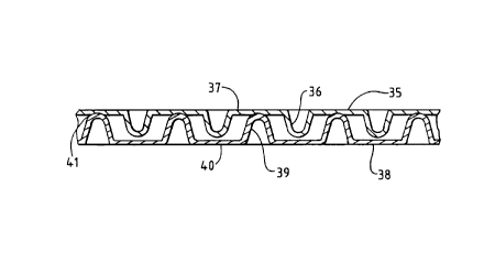
Figure 2 illustrates a conventional two-
ply paper product with nested embossments which can
be formed in accordance with U.S. Patent Nos.
3,556,907 and 3,867,225. An upper ply 35 of paper
sheet material is provided with downwardly
projecting embossments 36 and unembossed areas 37
between the embossments. A lower ply 38 of paper
sheet material is provided with upwardly extending
embossments 39 and unembossed areas 40 between the
embossments. The two plies are arranged so that
the embossments of one ply extend into the spaces
between the embossments of the other ply. Adhesive
41 is applied to the embossments 39 of the lower
ply for adhesively securing the embossments 39 to
the unembossed areas 37 of the upper ply.
Figure 3 illustrates a conventional
embossing machine for producing two-ply paper
CA 02280400 1999-08-13
_ 7
products with foot-to-foot embossments. A top web
44 which is unwound from an unwind stand (not
shown) passes over an upper rubber-covered roll 45
and a steel embossing roll 46. The embossing roll
is engraved to provide embossments or radially
outwardly extending projections 47 and unembossed
areas 48 between the projections.
The embossing roll 46 is rotatably
mounted in the embossing machine, and as the
embossing roll 46 and the rubber covered roll 45
rotate, projections 47 on the embossing roll 46
press the upper web into the rubber-covered roll 45
and form embossments 50 on the upper web. Adhesive
or glue is picked up from an adhesive fountain (not
shown) by a transfer roll 51, and the glue is
transferred by transfer roll 52 to an applicator
roll 53. The applicator roll 53 contacts the
embossments 50 of the upper web and transfers glue
to the embossments.
A lower web 54 is unwound from another
unwind stand and passes over a lower rubber-covered
roll 55 and a second steel embossing roll 56. The
embossing roll 56 is also provided with embossments
or projections 57 and unembossed areas 58. The
projections 57 on the second embossing roll press
the lower web into the rubber-covered roll 55 and
form embossments 59 on the lower web.
The two embossing rolls are arranged so
that the embossments of the two webs are aligned
and are pressed together where the projections of
the embossing rollers meet at the nip 62 between
the embossing rolls. As the embossments of the
webs are pressed together, the adhesive on one of
the embossments 50 secures the two plies together.
The resulting laminated two-ply embossed product 63
advances away from the embossing machine for
further processing operations, for example, in a
- CA 02280400 1999-08-13
- 8 -
rewinder line.
The second embossing roll 56 is rotatably
mounted in the embossing machine. The second
embossing roll is also advantageously pivotable
relative to the first embossing roll 46 so that the
nip 62 can be adjusted. The rotational or
longitudinal axes 46a and 56a of the embossing
rolls are parallel.
Figure 4 illustrates a conventional
embossing machine for producing two-ply paper
products with nested embossments. An upper web 65
from an unwind stand advances over a bowed roll 66
and around an upper rubber-covered roll 67. An
upper embossing roll 68 having projections or
embossments 69 presses the upper web into the
rubber-covered roll 67 to form embossments in the
upper web.
A lower web 71 is advanced from another
unwind stand over a bowed roll 72 and around a
lower rubber-covered roll 73. A lower embossing
roll 74 having projections or embossments 75
presses the lower web into the rubber-covered roll
73 to form embossments in the lower web.
Adhesive is applied to the embossments of
the lower web by an adhesive-applying roll 76 which
is supplied with adhesive by transfer rolls 77 and
78 and a fountain (not shown).
The axes of rotation 68a and 74a of the
upper and lower embossing rolls are parallel, and
the rolls are separated to provide an open nip 80.
The projections 69 on the upper embossing roll are
offset from the projections 75 on the lower
embossing roll so that the projections of the two
embossing rolls mesh at the nip 80. The embossed
upper web 65 leaves the upper embossing roll 68 at
the nip 80 and meshes with the embossed lower web
71 on the lower embossing roll. The two webs are
- CA 02280400 1999-08-13
_ g _
pressed together at a nip 81 between a rubber-
covered marrying roll 82 and the lower embossing
roll 74, and the adhesive on the embossments of the
lower web is pressed against unembossed areas of
the upper web to secure the two webs together.
Figure 5 illustrates the laminated two-
ply nested embossed product as it is advanced from
the marrying roll. The lower web 71 includes
upwardly extending embossments 83 and non-embossed
areas 84. The upper web 65 includes downwardly
extending embossments 85 and non-embossed areas 86.
The embossments of each web are positioned in the
unembossed areas of the other web, and the glue on
the embossments 83 secures the embossments to the
unembossed areas 86 of the upper web.
Figure 6 illustrates an embossing pattern
which can be engraved on both embossing rolls for
use in either a foot-to-foot embossing machine or a
nested embossing machine. The same embossing
pattern is used on each embossing roll.
The arrow A indicates the machine
direction, i.e., the direction in which the web
advances over the embossing roll and through the
embossing machine. The arrow B indicates the
cross-machine direction which extends parallel to
the rotational axis of the embossing roll.
The embossing pattern includes
embossments which are represented by black marks,
for example, 90, 91, and 92. The unmarked areas
which surround the embossments, for example, areas
93, 94, and 95, are unembossed areas. The
embossing pattern of Figure 6 includes a decorative
rectangular design represented generally by the
arrow 96 which repeats in both the machine
direction A and the cross-machine direction B. The
design 96 is formed by outer and inner rectangular
dot-dash lines 97 and 98 which are formed by
- CA 02280400 1999-08-13
- 10 -
circular and oval embossments and inner floral or
star-shaped designs 99 which are formed by four
slightly oval-shaped embossments.
When the embossing pattern of Figure 6 is
used to produce foot-to-foot embossments, the two
embossing rolls of Figure 3 are positioned in the
embossing machine of Figure 3 so that the identical
embossing patterns on the two rolls are aligned,
i.e., each of the projections or embossments on one
of the embossing rolls is aligned with a
correspondingly shaped projection or embossment on
the other embossing roll. The circumferential and
axial positions of one or both of the embossing
rolls can be adjusted to facilitate the alignment
step. The embossing rolls will therefore produce
two embossed webs having the embossing pattern of
Figure 6 in which the embossing patterns are
aligned and superimposed.
When the embossing pattern of Figure 6 is
used to produce nested embossments, the embossing
rolls are arranged as in Figure 4. One of the
embossing rolls is shifted axially in the cross-
machine direction relative to the other roll so
that the embossing patterns on the rolls are
slightly shifted or offset. Each projection or
embossment on each of the embossing rolls is
aligned with a space or unembossed area of the
other embossing roll.
Figure 7 illustrates the embossing
pattern of Figure 6 which is embossed on two
superimposed webs in a nested configuration. The
pattern on one of the webs is slightly shifted in
the cross-machine direction relative to the pattern
on the other web. The embossed dot-dash lines 97
and 98 of one of the webs are offset slightly from
the corresponding embossed dot-dash lines 97' and
98' of the other web. Similarly, the star-shaped
- CA 02280400 1999-08-13
- 11 -
designs 99 of one of the webs are offset slightly
from the corresponding star-shaped designs 99' of
the other web.
When the embossing pattern of one of the
webs is shifted relative to the embossing pattern
of other web to produce a nested configuration,
each of the embossments of one of the webs is
aligned with an unembossed area of the other web,
and each of the embossments of the other web is
aligned with an unembossed area of the first web.
The dimension of each of the embossments
of Figure 6 in the cross-machine direction is less
than the space between adjacent embossments in the
cross-machine direction. Accordingly, the
embossments on one of the webs can be shifted in
the cross-machine direction so that the embossments
are aligned entirely within the spaces on the
pattern of the other web. The amount of shifting
of the pattern is controlled so that the
embossments of the two webs nest and do not contact
each other.
Figure 8 illustrates another embossing
pattern which can be used to produce either foot-
to-foot embossments or nested embossments. The
embossing pattern includes a decorative design 101
which repeats in both the machine direction A and
the cross-machine direction B. The decorative
design 101 includes an outer rectangular dashed
line 102 form by embossments, an inner circular
dashed line 103 formed by embossments, an embossed
floral design 104 inside of the circle 103, and an
embossed dot design 105 in each corner of the
rectangle 102.
When the pattern of Figure 8 is used to
produce foot-to-foot embossments, two embossing
rollers having the same embossing pattern of Figure
8 are mounted in the embossing machine of Figure 3
CA 02280400 1999-08-13
- 12 -
so that the embossments of each embossing roll are
aligned with corresponding embossments of the other
embossing roll.
Figure 9 illustrates how the embossing
pattern of Figure 8 can be used to produce nested
embossments. One of the embossing rolls in Figure
4 is shifted slightly in the cross-machine B
direction relative to the other embossing roll so
that the embossments of each roll are aligned with
unembossed areas on the other roll. The
rectangular line of embossments 102 of one web is
offset slightly from the corresponding rectangular
line of embossments 102' of the other web, and the
circular line 103 of embossments 103 of one web is
offset slightly from the corresponding circular
line of embossments 103' of the other web.
Similarly, the floral design 104 of one web is
offset slightly from the floral design 104' of the
other web, and the dot designs 105 and 105' are
offset.
Figure 10 illustrates another embossing
pattern which can be used to produce foot-to-foot
or nested embossments. The embossing pattern
includes a large rectangular design 108 and a small
rectangular design 109. Each of the rectangular
designs repeats in both the machine direction and
the cross-machine direction.
The large rectangular design 108 includes
an outer rectangular line 110 of embossments, an
inner floral design 111 of embossments, and an
embossed dot design 112 in each corner of the
rectangle. The small rectangular design 109
includes a rectangular line 113 of embossments and
an inner floral design 113 which is similar to the
floral design 111 but which is rotated 450.
When the embossing pattern of Figure 10
is used to produce foot-to-foot embossments, the
CA 02280400 1999-08-13
- 13 -
two embossing rolls are rotatably mounted so that
the embossments on each embossing roll are aligned
with correspondingly shaped embossments on the
other embossing roll.
Figure 11 illustrates how the embossing
pattern of Figure 10 can be used to produce nested
embossments. One of the embossing rolls of Figure
4 is both rotated slightly and shifted axially
slightly relative to the other embossing roll so
that the embossing pattern of one web is shifted in
both the machine direction and in the cross-machine
direction, i.e., the embossing pattern of one web
is shifted generally diagonally relative to the
embossing pattern of the other web.
In the nested configuration illustrated
in Figure 11, the small rectangular design 109 of
one web is positioned inside of the large
rectangular line 110' of the other web. The dot
design 112' of the second web is located inside of
the corners of the small rectangle 113 of the first
web. The floral design 114 of the first web and
the floral design 111' of the second web mesh with
each other so that the individual embossments of
each of the floral designs are aligned with
unembossed areas of the other floral design.
Figure 12 illustrates yet another
embossing pattern which can be used to produce both
foot-to-foot and nested embossments. The embossing
pattern includes a large generally circular
embossed design 115, a starburst embossed design
116 inside of the circular design, and a smaller
embossed circular design 117.
Figure 13 illustrates how the embossing
pattern of Figure 12 can be used to produce nested
embossments. One of the embossing rolls is shifted
both circumferentially and axially relative to the
other embossing roll so that the embossments of one
CA 02280400 1999-08-13
- 14 -
of the embossing rolls are aligned with unembossed
areas of the other embossing roll. The embossing
pattern of one of the webs is thereby shifted in
both the machine direction and the cross-machine
direction so that the embossments nest.
Figures 14, 16, 18, 20, and 22 illustrate
other embossing patterns which can be used to
produce both foot-to-foot embossments and nested
embossments. In each case, when nested embossments
are produced, one of the embossing rolls is shifted
both circumferentially and axially so that the
embossing pattern of one of the webs is shifted
relative to the embossing pattern of the other web
in both the machine direction and the cross-machine
direction. Figures 15, 17, 19, 21, and 23
illustrate the nested embossment configurations
which are formed by two identical embossing
patterns.
Each of the embossing patterns
illustrated herein is formed from decorative,
aesthetically pleasing designs. Each design
includes design elements which repeat in either or
both of the machine direction and the cross-machine
direction. The dimensions of the embossments in
either or both of the machine direction and the
cross-machine direction and the spacing between
adjacent embossments in either or both of the
machine direction and the cross-machine direction
are such that the embossments on one of the webs
can be shifted in either or both of the machine
direction and cross-machine direction relative to
the other web so that each embossment of each web
is aligned with an unembossed area of the other
web.
Many other embossed patterns can be
designed for producing both foot-to-foot and nested
embossments. Such embossed patterns advantageously
CA 02280400 1999-08-13
- 15 -
include embossments which form geometric shapes,
for example, circles, squares, rectangles, and
various other polygons such as hectagons, octagons,
diamonds, and embossments which form decorative
designs inside of the geometric shapes. The size
and shape of the embossments and the space between
embossments are such that the embossed pattern of
one web can be shifted in either or both of the
machine direction or the cross-machine direction so
that the embossments of one web will nest between
and not contact the embossments of the other web.
Certain design criteria should be applied
when designing the embossing patterns of this
invention. The bond area between the two webs,
i.e., the area of the webs which is glued together,
should be within the range of 4% to 20% of the
total web area per square inch of web. A more
preferred range of bond area for foot-to-foot
embossments is 9% to 13%, and a more preferred
range of bond area for nested embossments is 6% to
12%. Since the bond area for a particular
embossment pattern is generally somewhat different
for any particular square inch of web, the bond
areas in 10 different square inches of web are
averaged in order to determine whether the bond
area falls within the foregoing ranges.
In order to better appreciate the
dimensions of the embossment patterns which are
described herein, the patterns illustrated in
Figures 6-23 are drawn to scale on the original
drawings of this patent application. Since the
drawings of the printed patent may be reduced, a
one inch scale is included in Figures 6, 8, 10, and
12.
The side wall angle or flank angle of the
embossments should be within the range of loo to
300, and while preferably within the range of 200
CA 02280400 1999-08-13
- 16 -
to 250. Referring to Figure 5, the side wall angle
is the angle A between the side wall of the
embossment and a vertical plane through the web.
The depth of the embossment should be
within the range of 0.040 to 0.080 inch for both
nested and foot-to-foot embossments, and more
preferably within the range of 0.050 to 0.060 inch.
Figures 3 and 4 illustrate two different
embossing machines for making foot-to-foot and
nested embossments. However, combination embossing
machines are available which can make both foot-to-
foot embossments and nested embossments on the same
machine. Referring to Figures 24 and 25, a
combination embossing machine 120 includes a frame
121 on which are rotatably mounted first and second
rubber-covered rolls 122 and 123 and first and
second steel embossing rolls 124 and 125. A
marrying roll 126 is pivotally mounted on the frame
by a pivot arm 127 for pivoting movement toward and
away from the first embossing roll 124.
A first web 128 travels over roll 129 and
around the first rubber-covered roll 122 and first
embossing roll 124. Adhesive is applied to the
first web by an enclosed fountain 130, anilox roll
131, and applicator roll 132.
A second web 134 travels over a roll 135
and around the second rubber-covered roll 123 and
second embossing roll 125.
Figure 24 illustrates the combination
embosser configured to produce foot-to-foot
embossments. The marrying roll 126 is pivoted away
from the first embossing roll 124. Both of the
embossing rolls 124 and 125 have the same embossing
pattern, and the embossments of the two rolls are
aligned so that the embossments on the two webs are
pressed together in the nip between the two
embossing rolls. The laminated two-ply product 136
CA 02280400 1999-08-13
- 17 -
extends from the second embossing roll 125 and over
a roll 137.
Figure 25 illustrates the combination
embosser configured to produce nested embossments.
The marrying roll 126 is pivoted against the first
embossing roll 124.
The two embossing rolls 124 and 125 are
provided with the same embossing pattern, and one
of the embossing rolls is shifted in either the
machine direction, i.e., rotated, or shifted in the
cross-machine direction, i.e., moved axially, or is
shifted in both directions relative to the other
embossing roll so that the embossments of the two
rolls mesh. The embossed second web 134 meshes
with the embossed first web 128 in the nip between
the embossing rolls. The two webs are pressed
together at the nip between the rubber-covered
marrying roll 126 and the first embossing roll 124,
and the laminated two-ply sheet 136 travels from
the marrying roll 126 over the roll 137.
While in the foregoing specification, a
detailed description of specific embodiments of the
invention was set forth for the purpose of
illustration, it will be understood that many of
the details herein given can be varied considerably
by those skilled in the art without departing from
the spirit and scope of the invention.