Note: Descriptions are shown in the official language in which they were submitted.
CA 02280521 1999-08-OS
WO 98/34799 PCT/GB98/00358
- 1 -
TYRE PRESSURE WARNING SYSTEM
This invention relates to a tyre pressure warning
system of the type which can be used on vehicles to advise
the driver if the pressure in any of the tyres on the
s wheels of the vehicle changes from a predetermined value
by more than a given amount. Typically, it will be used
to warn the driver of deflation of the tyre.
The present invention is an improvement on a system
known as TireMate which has been sold in the United
io States. This consists of a pressure sensor/transmitter,
which replaces the dust cap on the outer end of a tyre
valve. The sensor/transmitter is a mechanical pressure
sensor. It is preset with a reference pressure, the ideal
pressure for the tyre on which it is to be mounted, and a
is triggering pressure. If the pressure in the tyre falls to
the triggering pressure the sensor/transmitter transmits
only its identity to a control unit which then indicates
to the driver that a fault has occurred on that. Thus,
when the pressure in the tyre becomes too low the driver
2o will be warned of this and will have the option of doing
something about it. The sensor/transmitter unit transmits
continuously until the battery powering it is discharged.
One problem with this system is that
sensor/transmitter units have to be preset with desired
z5 and triggering pressures. This is normally done at
manufacture and means that units cannot easily be switched
to other vehicles with tyres that run at different
pressures.
The present applicants have appreciated that the
so driver of the vehicle does not need to be constantly
reminded of the pressure in the tyre and, thus, does not
CA 02280521 1999-08-OS
WO 98/34799 PCTlGB98/00358
- 2 -
need repeated transmission of pressure data from the
sensor to the data processing and display unit. All that
the driver requires is a warning of some kind when the
pressure in the tyre differs from the desired pressure by
s more than a predetermined amount. It is not necessary to
transmit the exact pressure data. Thus, a preferred
embodiment of the invention provides a system in which the
sensor/transmitter only transmits an over or under
pressure signal to the data processing and display unit
io when the pressure in the tyre differs from the desired
pressure by more than a predetermined amount.
Another problem with the prior art system arises from
the fact that the temperature of tyres on motor vehicles
can vary considerably. The temperature of tyres on a
is vehicle which has been driven for some time will be
significantly higher than the temperature at rest and this
will cause a significant increase in pressure. Also, in
some environments, e.g., the desert, temperatures between
night time and day time vary by a considerable amount
2o thereby leading to variations in pressure entirely
dependent on temperature.
In accordance with a further embodiment of the
present invention, a sensor/transmitter device is provided
to replace a standard dust cap. A thermistor is provided
2s and is exposed to the gas filling the tyre and thus is
sensitive to temperature changes in the gas. A software
driven microprocessor receives a signal from the
thermistor and is thus able to take account of temperature
changes in determining whether or not there has been any
3o increase or decrease in the real pressure in the tyre.
The invention is defined in the appended claims to
which reference should now be made.
CA 02280521 1999-08-OS
WO 98/34799 PCT/GB98/00358
- 3 -
Preferred embodiments of the invention will now be
s
described in detail by way of example with reference to
the accompanying drawings in which:
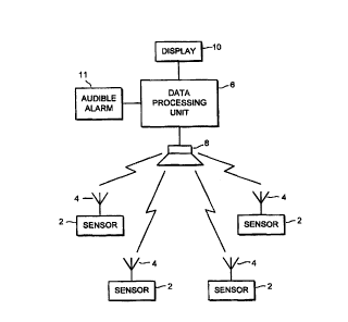
Figure 1 shows a schematic diagram of a system
embodying the invention;
Figure 2 shows a schematic diagram of a sensor
embodying the invention; and
Figure 3 shows a schematic diagram of a further
embodiment of the invention for use on vehicles with
io detachable trailers.
In Figure 1, there are shown four sensor units 2 each
coupled to a respective transmitter 4. These units are
included in a unit which screws onto a tyre valve and
replaces its dust cap. On a four-wheel vehicle the system
is would be as shown in Figure 1 with four sensor/transmitter
units, one attached to the dust cap on each wheel. It can
however be used on two wheel vehicles or vehicles with
more than four tyres or wheels.
The pressure transducers used in the
zo sensor/transmitter units are electronic sensors under
microprocessor control. They are controlled to transmit to
a control unit an identification code when they are
installed on a tyre. They are also controlled to measure
and record the pressure they first encounter when they are
2s installed on a tyre. This is stored in memory and is used
for comparison with the tyre pressure during use to
determine wether the tyre pressure has changed by more
than a predetermined amount. Preferably this change is
monitored as a percentage of the first encountered
ao pressure, e.g. 15%. The transducers used preferably have a
range from 0.5 to 10 bar and this enables the same
CA 02280521 1999-08-05
WO 98/34799 PCT/GB98/00358
- 4 -
sensor/transmitter units to be used on a wide range of
vehicles.
A data processing unit 6 is provided in the cab of
the vehicle in a position where it can be viewed by the
s driver. This data processing unit is coupled to a
receiver 8 which receives signals transmitted by the
transmitters 4. It is also coupled to a display 10 which
is used to display tyre deflation/inflation warning
information to the driver. The display 10 is preferably an
io alphanumeric display of, for example, the liquid crystal
type. Thus it can provide instructions and information to
the user.
The sensors are coupled to the microprocessor which
monitors the output signal from its respective sensor and,
i5 if the signal alters in such a way as to indicate that the
pressure in the respective tyre has changed from the first
encountered pressure by more than the predetermined
amount, the processor controls the transmitter to transmit
a warning signal to the data processing unit 6 which
2o receives it by means of receiver 8. This warning signal
comprises an identification signal identifying the sensor.
In this particular embodiment the identification signal is
a 16-bit coded signal which enables over 65,000 different
sensor identification codes to be used. This makes the
25 chance of a signal from a sensor with a corresponding ID
on another vehicle being sent to the data processing unit
6 very remote. Previous systems such as the TireMate
system included the possibility of only 14 individual
settings for sensor identification codes.
3o The sensor/transmitter units are arranged to transmit
every 24 hours an OK signal to the data processing unit 6
if no fault condition is detected within a 24 hour period.
CA 02280521 1999-08-OS
WO 98/34799 PCT/GB98/00358
- 5 -
The purpose of this signal is to ensure that the data
processing unit has information indicating that all
sensor/transmitter units on a vehicle are working. Thus,
if a fault develops on a unit or its battery runs out of
s power, no OK signal will be sent to the data processing
unit 6 and this can then indicate to the driver via the
display 10 that there is a problem with the
sensor/transmitter unit on a particular wheel of the
vehicle. Furthermore, the sensor/transmitter is preferably
io arranged to detect faults with the sensor and to transmit
to the control unit a sensor fault signal to the driver
indicating that a problem has occurred with a particular
sensor.
The sensor units are designed to determine the
i5 pressure of the tyres on which they are installed, store
this pressure in memory and, subsequently, trigger a fault
condition transmission when the pressure change within the
tyre is, for example, plus or minus 15% from the pressure
originally measured and stored. Thus, there is no
2o requirement for triggering of fault condition signals at
predetermined pressures.
when a fault condition is detected the
sensor/transmitter in this embodiment sends the fault
signal repeatedly over a period of 30 seconds. The
z5 transmission is then terminated to save the battery life
of the sensor. Thereafter, the alarm transmission is
repeated every 15 minutes for a 30 second period. To
rectify a fault the sensor/transmitter unit is removed
from the tyre by unscrewing the dust cap. Exposure of the
3o transducer to atmospheric pressure causes the sensor to
reset and causes the fault transmission to cease. These
timings can of course be varied as desired.
CA 02280521 1999-08-05
WO 98/34799 PCT/GB98/00358
- 6 -
Another embodiment of a sensor/transmitter unit is
shown in Figure 2. In this, it can be seen that the
sensor comprises a sensor unit 2 (preferably an electronic
sensor) which is responsive to the tyre pressure and a
s thermistor 12 (temperature dependent resistor) which
changes resistance as the temperature in the tyre changes.
The processor 14 monitors the signal from the sensor 2 and
from the thermistor 12. From this, it is able to
determine what temperature increase or decrease in the
io tyre has occurred and thus is able to compensate the
signal from the sensor for this temperature
increase/decrease. This avoids the sending of a spurious
fault condition signal when pressure increases or
decreases purely because of a large change in temperature.
i5 It ensures that fault transmissions only occur when there
is some other cause for an increase/decrease in pressure.
The data processing and display unit is used to
record the identities of sensor/transmitter units
installed on a vehicle. This information is stored in
2o memory. The control unit prompts a person installing the
sensor/transmitter units to install the units on each tyre
in turn. Prompting is done via the display 10 where an
indication of the tyre on which the next unit to be
installed is made. When each unit is installed, the
zs initial exposure to the tyre pressure causes it to
transmit its identification code to the control unit. Thus
the control unit is able to record the identification code
for the unit installed on each tyre.
The data processing unit validates any transmission
so received by ensuring that it is repeated several times in
the same format. This it does during the transmission
period of 30 seconds from a fault condition being detected
CA 02280521 1999-08-OS
WO 98/34799 PCT/GB98/00358
and transmission of that commencing. This is done to
exclude spurious transmissions and to ensure that the
identity code received relates to a sensor which has
previously been recorded as being installed on the
s particular vehicle.
Details of any fault transmission which are received
by the data processing and display unit are stored in
memory together with the tyre position concerned and the
time at which that observation was made. Thus, if the
io fault occurs while the vehicle is not being driven it is
stored and will be provided to the driver via the display
and an audible alarm 11 when the vehicle is next switched
on. Similarly, the failure of any sensor to transmit an
OK signal will be stored in memory together with the tyre
is position concerned so that the driver will be alerted of
the failure of that sensor/transmitter to operate
correctly.
In many commercial vehicles, separate tractor and
trailer units are used, particularly in the road haulage
2o industry. Trailers may be disconnected from tractors for
a considerable period of time and may in fact be
reconnected to different tractors. If a tyre deflation
should take place whilst a trailer is disconnected, the
tractor unit with the standard data processing and display
2s unit will not be in the proximity and, thus, details of
the failure will not be stored. To overcome this, a
separate data transceiver unit is provided on a trailer.
This is illustrated in Figure 3. In this, a data
transceiver unit 16 is provided mounted on a trailer and
3o is coupled to a receiver 18. This receives signals from
sensors/transmitters mounted on the wheels of the trailer.
It includes a memory which stores any fault condition
CA 02280521 1999-08-OS
WO 98/34799 PCT/GB98/00358
_ g
signals and the OK signals received while a trailer is not
connected to a tractor. A separate power supply is
included in the data transceiver unit 16 and this is
preferably a rechargeable battery which is recharged when
s the transceiver is connected to the power supply of a
tractor.
On the tractor is provided a normal data processing
unit 6 and display 10 of the type shown in Figure 1. This
is coupled to a receiver 8 which receives signals from
io sensor/transmitters mounted on the wheels of the tractor
unit.
A connector 20 is used to couple the data processing
unit to the data transceiver when the tractor unit is
coupled to the trailer for power supply. On initial
is coupling, all data stored by the data transceiver is down
loaded to the tractor unit. This comprises the identities
and locations of the sensors mounted on the trailer,
whether or not any fault condition has occurred on any of
these, and details of whether the OK signals required
2o every 24 hours have been received.
The connection 20 between the data transceiver 16 and
the data processing unit 6 need not be a hard-wired
connection. The data transceiver could be provided with a
transmitter 22 which, when a tractor is linked to the
2s trailer, could be organised to transmit all the relevant
information to a receiver 24 on the data processing unit
6. Thereafter, signals from the trailer sensor
transmitters could be received either by the data
transceiver 16 or by the data processing unit 6.
so Using this arrangement enables tractors and trailers
to be interchanged without having to reprogramme the tyre
pressure warning system.