Note: Descriptions are shown in the official language in which they were submitted.
CA 02280822 1999-08-10
WO 99/11025 PCT/US98/02084
METHOD OF SHARING COMMUNICATION CHANNELS UTILIZING
BOTH CONTENTION AND POLLING SCHEMES
BACKGROUND OF THE INVENTION
s Field of the Invention
This invention relates to a method of sub-channelizing a broadband
medium and assigning predefined protocols to respective subchannels thereof.
More
particularly, it relates to a method for sharing sub-channels based on the
nature of the
data to be transferred in a multi-channel communication network.
to
Background of Related Art
The general trend of the prior art has been to establish high bandwidth
channels for the transmission of data to improve performance. For instance,
recent
improvements in dial-up modems has been the migration from 28.8Kb/s to 56
Kb/s.
is It is conventionally assumed that larger bandwidths provide better
performance. In
the case of shared channels, as the bandwidth of channels increases, so does
the
complexity of the channel, including the protocol used. Moreover, larger
bandwidths
increase the possibility that noise at a particular frequency will erode the
reliability of
communications.
2o In a shared channel environment, media access protocols involve
contention or polling to gain channel access. For instance, US Patent No.
5,563,883
discloses a controilerwhich periodically broadcasts a polling message
simultaneously
to a plurality of cable modems over a shared downstream communication channel.
The cable modems then contend for access to a single upstream channel. If
2s messages of more than one modem collide with one another, a binary search
method
implemented in a media access controller arbitrates between and isolates
colliding
modems. However, only one upstream channel is available for the colliding
modems
to communicate upstream back to the controller. Thus, all modems assigned to a
particular upstream channel must not only contend for channel access to
respond to
3o the downstream broadcast poll, but any subsequent data transmission must
also
*rB
CA 02280822 1999-08-10
WO 99/11025 PCT/US98/02084
contend for the same single upstream channel. This leads to congestion and
lower
performance.
U.S. Patent No. 4,829,297 discloses a communication method wherein
the same polling technique is used in two channels. While this increases
s performance only because it provides two upstream paths rather than just
one, it fails
to segregate busy users from inactive or idle users.
U.S. Patent No. 4,754,42fi teaches the prioritized polling technique of
placing a higher priority on some users, and thus polling those higher
priority users
more frequently. However, all upstream communications remain on a single
channel.
io Thus, the performance of the higher priority users is increased, but at the
expense of
the non-high priority users.
Other patents such as U.S. Patent No. 5,572,517 to Safadi discourage
the use of a polling scheme in a shared network environment altogether.
is SUMMARY OF THE INVENTION
The present invention exploits the beneficial aspects of both contention
and polling protocols by employing dynamic allocation of upstream channels to
move
users of a network between diverse channels utilizing difFerent protocols
selected to
maximize data transfer based on the instantaneous transmission status of the
user.
2o For instance, non-responding users (e.g., user equipment that is
powered down) are assigned to a first group of channels utilizing a contention-
only
protocol in the upstream direction. After detection by a media access
controller, the
status of responding and active users are reclassified to use a second group
of
channels utilizing a polling protocol that is maximized for low latency, e.g.,
a limited-1
Zs polling scheme. Users demanding heavy usage with lengthy transmissions
reclassified to use a third group of upstream channels that are maximized for
high
throughput, e.g., channels that have an exhaustive polling or approximately
exhaustive polling scheme. The media access controller is capable of switching
the
users' upstream channels dynamically and intelligently on a packet-by-packet
basis.
3o Rules based on activity level of the user are implemented to determine when
the user
is to switch between channel groups. The user can transmit on any of a
plurality of
upstream channels or sub-channels, utilizing either a contention-based
protocol, or
any of a plurality of polling-based protocols, on a per-packet basis.
2
CA 02280822 1999-08-10
WO 99/11025 PCT/US98/02084
Contention based algorithms work well when there are a large number
of subscribers but only a few of them are active at any time (i.e. in light
traffic), while
polling based algorithms work well in heavy traffic. The present invention
utilizes the
efficiencies of both protocols. First, by initially assigning non-responding
users (e.g.
s powered-down users) to a channel chosen at random out of the group of
contention
mode channels. Once it becomes active, the user is moved to a first level
polling
mode channel selected from a first group of polling mode channels operating
with a
polling protocol that is maximized for low latency. Then, as necessary, the
user is
moved again to a higher level polling mode channel selected from a second
group of
to polling mode channels operating with a polling protocol that is maximized
for
maximum throughput. Additional levels of polling mode channel groups blending
a
mix of low latency and maximum throughput, e.g., greater than limited-1 type
polling,
although adding to the complexity of the overall protocol, can add further
efficiencies
to the communication system.
is Ranging and synchronization between the media access controller and
the users are not necessary according to the present invention because of the
use
of contention mode and polling mode channels.
Moreover, the present invention makes intelligent use of an expanded
number of smaller bandwidth channels formed from a smaller number of larger
2o bandwidth channels. It is found that there is a greater likelihood of
having a larger
number of usable smaller bandwidth upstream channels than there is of having
an
equivalent amount of usable larger bandwidth upstream channels due largely to
the
noise characteristics in the upstream path of a cable TV facility. Commonly
assigned
U.S. Patent Application Nos. 081702,932 and 08/735,110 disclose the sub-
Zs channelization of a communication channel and are explicitly incorporated
herein by
reference.
In view of the foregoing, it is an object of the present invention to
maximize the throughput and reliability of a plurality of upstream channels
from a
plurality of users to a host computer or controller.
3o It is a further object of the present invention to intelligently pass
packet
data from a single user to a host computer or controller over a selected one
of a
plurality of upstream channels operating with different protocols chosen based
on the
data itself.
3
CA 02280822 1999-08-10
WO 99/11025 PCT/US98/02084
It is also an object of the present invention to maximize the performance
of an overall polling scheme by providing classifying a plurality of channels
into a sub-
plurality of groups, each group utilizing a different polling scheme.
it is a further object to provide a protocol which switches upstream
s communications between different polling mode channel groups based on
optimized
performance criteria.
This summary is not intended to limit the invention to any extent beyond
that defined in the appended claims.
io BRIEF DESCRIPTION OF THE DRAWINGS
These and other objects of the invention will be understood by persons
of ordinary skill in the art after review of this specification and with
reference to the
drawings, in which:
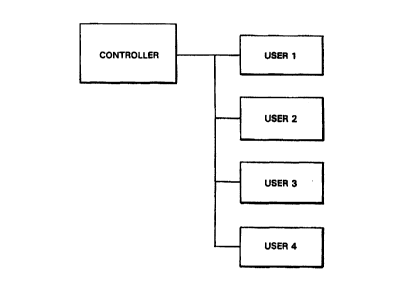
Fig. 1 shows a network including a controller {e.g., a TV facility head
is end) and a plurality of users (e.g., cable modems);
Fig. 2 shows a user activity model for FTP and WWW type applications
requiring high throughput for optimized performance;
Fig. 3 shows a user activity model for Telnet and Rlogin type
applications requiring low latency for optimized performance;
2o Fig. 4 shows a grouping of available upstream channels into three
groups based on an operating protocol;
Fig. 5 shows the calculation of delay between a user which is closest to
the host computer or controller and a user which is farthest from the host
computer
or controller;
2s Fig. 6 shows downstream polling (e.g., 'credit' messages) from the
controller to each of three users, and the response thereto (e.g., 'done'
messages)
sent in a selected polling mode upstream channel currently assigned to all
three
users;
Fig. 7 is a diagram of a controller state machine;
3o Figs. 7A to 7D(3) are flow charts showing procedures implemented at
various states of the controller state machine in the exemplary embodiment of
the
present invention;
4
CA 02280822 1999-08-10
Vh0 99/11025 PCT/US98/02084
Fig. 8 is a diagram of a user state machine; and
Figs. 8A to 8D are flow chart showing procedures implemented at
various states of the user state machine in the exemplary embodiment of the
present
invention.
s
DESCRIPTION OF ILLUSTRATIVE EMBODIMENTS
Fig. 1 shows a network including a host computer or controller 100 and
a plurality of users 101-104 according to the present invention. The network
may
encompass virtually any medium, wired or wireless. The host computer or
controller
io 100 may be, as in the exemplary embodiment, a TV facility head end, and the
users
101-104 may be cable modems installed in subscribers homes.
Fig. 2 shows Type I file transfer applications such as FTP, WWW, SMTP
and NNTP, and Fig. 3 shows Type II file transfer applications such as Telnet
and
Rlogin.
is When users operating Type I applications are busy communicating, they
cycle through alternate periods of bursting and processing. The sizes of the
bursts
are typically on the order of several thousand bytes of data. For maximum
throughput
and performance, Type ! applications should conclude their bursts as quickly
as
possible.
2o When users operating Type II applications are busy, they generate
relatively small packets on the order of a few bytes each, but on a more
continuous
basis as compared to Type I applications. For example, for Telnet and Rlogin
applications, a packet of only byte is generated each time the user types a
character
on his terminal, and is displayed only after it has been echoed back by the
receiver.
2s Type 11 applications are desirous of viewing typed characters as quickly as
possible,
and thus round trip latency must be minimized.
There is a conflicting interest between the needs of Type I applications
and the needs of Type II applications. The performance for Type I applications
is
optimized only at the expense of performance for Type II applications. Thus,
3o conventional systems utilizing a single channel and a single protocol,
i.e., contention
or polling, balance the needs of Type I applications against the needs of Type
II
CA 02280822 1999-08-10
WO 99/11025 PCT/US98/02084
applications. The present invention does not balance the needs of Type I
applications
against the needs of Type II applications. Instead, it optimizes both the
needs of
Type i applications and the needs of Type II applications by providing
separate
communication channels for each type application. The present invention
satisfies
s both the need for high throughput by Type I applications and the need for
low latency
by Type II applications by allowing each user to communicate with the
controller via
distinct channels or sub-channels operating with different protocols.
Some applications alternate between Type I and Type II during the
course of a session. For example, a file transfer using file transfer protocol
{FTP)
~o (i.e., Type II application) is typically preceded by several small messages
that set up
the FTP control connection (i.e., Type I application). As another example, a
Telnet
user (i.e., Type II user) may be scrolling through several screens of data
(i.e., Type
I communications). Even though applications alternate between communications
which require rapid throughput and those which require low latency,
conventional
Is systems typically classify the application as either a Type I application
or a Type II
application. The present invention ciassi~es applications dynamically as
either Type
I or Type II based on their current traffic.
In traditional time-division multiple access (TDMA) based medium
access channel (MAC) protocols, users transmit a first packet using contention
ao protocols, and subsequent packets by piggybacking on the initial packet.
The protocol of the exemplary embodiment of the present invention
differs from contention-only communication protocols in several respects.
According
to the present invention, each user is provided with access to any one of a
plurality
of upstream channels or sub-channels operating under different protocols,
based on
2s characteristics of the data. Of course, assignment of the users to
particular channels
may be based on other rules established to provide the users with desired
performance.
Initial data is transmitted on one upstream channel in response to a
broadcast polling message utilizing a contention protocol in a channel
designated for
3o contention mode communications. After the user is detected as active,
subsequent
data is transmitted utilizing a polling protocol in a polling mode channel. It
is desirable
s
CA 02280822 1999-08-10
WO 99/11025 PCT/US98/02084
to avoid any sustained data transfers in the contention mode channel. It is
found that
this provides a more deterministic performance for users.
In the exemplary preferred embodiment of the present invention, a head
end controller at a cable TV facility (i.e., controller) communicates with a
plurality of
s cable modems in subscribers homes (i.e., users). A plurality of upstream
channels
are formed within the bandwidth of the communication path between the user and
the
controller, e.g., a cable. The number of upstream channels from the cable
modems
to the head end controller is maximized. Sub-channels can be formed from the
channels by frequency division or by time division to provide additional
~o communication channels for use by the present invention. The channels and
sub-
channels can be of equal bandwidth, or can be of differing bandwidth. In the
disclosed embodiment, a 6 MHz TV channel is frequency divided into three 2 MHz
channels, although the 6 MHz TV channel could instead be divided into only two
3
MHz channels, six 1 MHz channels, or even unequal bandwidth channels such as
one
~s 2 MHz channel and four 1 MHz channel. Moreover, a plurality of 6 MHz TV
channels
are subdivided to provide one common group of communication channels to be
used
by various contention and polling mode protocols.
In the preferred embodiment, the available upstream channels are
classified into particular protocol groups, e.g., Group A, B or C. Group A
channels
2o handle communications utilizing a contention protocol and thus operate as
contention
mode channels. Group B channels handle shorter length 'bursty' communications
utilizing a limited type polling protocol and thus operate as limited polling
mode
channels. Group C channels handle longer length communications utilizing an
exhaustive type polling protocol and thus operate as exhaustive polling mode
2s channels.
Given a plurality of available upstream channels, only one upstream
channel type need utilize a contention protocol, whereas the remaining channel
types
can utilize a polling protocol. Alternatively, as many as all but one channel
type may
utilize a polling protocol. By grouping channels into use for either
contention mode
so or polling mode transmissions, the complexity of the overall protocol is
simplified
7
CA 02280822 1999-08-10
WO 99/11025 PCT/US98/02084
because of the elimination of complex operations such as ranging and
synchronization.
According to the exemplary embodiment, the use of a contention mode
channel in Group A is restricted to initial communications from the user to
the
s controller common to activation procedures. A newly active user is one which
has not
transmitted data for a period of time, e.g., within the previous five minutes.
Of course,
this length of time can vary depending upon the application.
In such a case, the user initially selects one of the available Group A
contention mode channels at random, and contends for that channel using a
to contention protocol. Once the initial contention mode communication is
received by
the controller, the user's upstream path is reassigned to a limited polling
mode
channel in Group B. Thus, subsequent data, e.g., subsequent packets, are
transmitted on a channel different from that over which the initial contention
mode
communications occurred.
~s In the preferred embodiment, the contention mode channels in Group
A are not utilized for significant data transfers, but instead for the
detection by the
controller of the activation of users. Thus, a relatively large number of idle
users can
be supported on only one or a few contention mode upstream channels without
any
significant degradation of service.
ao In assigning users among the polling mode channels, it is not best to
allocate all Type I users in one group of channels and all Type II users in
the other
group of channels. Because of their bursty nature, only a fraction of the
total
allocated Type I users are actively transferring data at any one time, while
the
remaining Type I users are in-between bursts. Instead, it is desirable to keep
only
zs Type I users which are currently bursting together, while the remaining
Type I users
can be assigned to share the same group with Type II users. Thus, dynamic
allocation of resources is accomplished by the present invention, e.g. between
Group
B channels and Group C channels. This dramatically reduces the number of users
(e.g., cable modems) sharing channels allocated for bursting users, thus
increasing
3o performance even more.
8
CA 02280822 1999-08-10
WO 99111025 PCT/US98/02084
An estimate of the number of Type I users which are bursting
simultaneously can be calculated as follows from Little's Law.
N = (MIR)T
Wherein N is the average number of simultaneously bursting users, M is the
number
s of active Type I users in the system, R is the average rate of transactions
generated
by an active Type I user (once every R seconds), and T is the average time in
seconds burst time it takes for a Type I transaction to complete.
For example, if M =100, R = 20 seconds, and T =1 second, then Little's
Law provides that the average number of simultaneously bursting users is N =
5.
Io Thus, out of one hundred Type I users that are busy, it is estimated that
statistically
only five are bursting at the same time. Thus, it is found that in order to
obtain good
performance, it is only necessary to provide enough Group C upstream channels
from the users (e.g., cable modems) to a controller (e.g., a cable headend) to
handle
the simultaneously bursting users. In this example, since N = 5, it is only
necessary
is to provide enough Group C channels sufficient to handle five simultaneously
bursting
users at the desired level of performance.
Fig. 4 shows sub-channel assignment and allocation according to one
embodiment of the present invention. K channels are assigned for detecting
activity
in idle users or cable modems utilizing contention mode protocols, and thus is
ao classified as a Group A contention mode channel. I channels are assigned
for
polling, non-bursting, but active users or cable modems and thus is classified
as a
Group B polling mode channel. J channels are assigned for polling bursting
modems
and thus is classified as a Group C polling mode channel.
as Contention Mode Channels - Group A
One contention protocol suitable for use in the contention mode channel
of the present invention utilizes a Binary Exponential Back-off based scheme.
Simulations have shown that a Binary Exponential Back-off scheme provides
adequate performance for a typical number of users (e.g., 1000) in a multiple
user
3o communication system, e.g., multiple cable modem subscribers served by a
cable TV
facility's headend. However, as the number of users utilizing the contention
mode
9
CA 02280822 1999-08-10
WO 99/11025 PCT/US98/02084
channel increases, transmission collisions occur more frequently and thus
transmission delays increase and performance decreases. Thus, according the
present invention performance is increased by dynamically moving transmissions
from
users between differently classified upstream channels, preferably on a packet-
by-
s packet basis.
An important parameter in contention mode channels is the minimum
upstream packet size LM~N. This value ensures the detection of a collision
between
multiple users at the controller. Fig. 5 shows the minimum upstream packet
size for
a contention mode channel.
io The last bit from the user or modem nearest to the controller or headend
arrives at the controller at a time T1 equal to whereas I is the size of the
downstream
CREDIT packet, L is the size of the upstream data packet, C(d) is the capacity
of the
downstream link, C(u) is the capacity of the upstream link, PDM,N is the delay
from the
headend to the nearest modem, and PD,"~ is the delay from the headend to the
i s farthest modem.
The first bit from the farthest modem arrives at time T2 equal to:
l
T2 = C(d) + 2PDMax
Thus, in order to ensure a collision, it is required that T1 zT2, which leads
to the
ao following condition:
L
C(u) ~ 2(PD~- - PDmN) OR
LM1N = 2C(u)(PD,~.~X - PDMIN)
According to the present invention, a controller (e.g., a headend in a
2s cable TV facility) broadcasts a polling CREDIT message to all users
desiring to
transmit packet information (e.g. all cable modems). Users that are in the
contention
mode and have a packet to transmit do so on a contention mode channel when
they
CA 02280822 1999-08-10
VVO 99/11025 PCT/US98/02084
receive the CREDIT message. U.S. Patent No. 5,586,121 describes the CREDIT-
DONE protocol and is expressly incorporated herein by reference.
Any collision between a plurality of users collide, then the collision is
detected at the controller, and the colliding users are informed of the
collision in the
s next broadcast {polling} CREDIT message sent by the controller in the
contention
mode channel. Colliding users then undergo a simple binary-exponential back-
off,
and re-transmit the collided message after a random number oftransmit
opportunities.
If there are multiple upstream contention mode channels available, e.g., Group
A
channels, then the user chooses one of the multiple upstream contention mode
~o channels at random for each transmission of a packet of data. Hence, if
there is more
than one contention mode channel, then there are effectively two sources of
randomness that help reduce collisions in the contention mode channels: a
first due
to the existence of a plurality of contention mode channels, and the second
due to the
binary-exponential back-off scheme.
~s A user with a packet of data to send monitors the primary contention
mode channel for the broadcast poll. Upon detection of the broadcast poll, the
user
transmits the number of CREDITED packets on a Group A channel chosen at
random.
Each user utilizes a simple Ethernet style binary back-off scheme. The
Zo controller periodically transmits a broadcast poll message on the
downstream
contention mode channel, with a period TIME1 equal to the maximum delay for
the
farthest modem to respond to the poll. In each polling cycle, the controller
informs the
users about the collision/no collision results from the previous broadcast
polling cycle,
e.g., by including a COLLISION bit in the CREDIT message. If a collision
occurred,
2s the user calculates a back-off window of size i , where i is a random
integer in the
range [0,2'-'], and I is the number of collisions which have occurred. The
user also
calculates j =min(max( i ,2"m~n),2"meX}, and attempts its next transmission
after j
polling cycles by the controller in the contention mode channel. After a
predetermined
number of successive re-transmissions without success, the packet of data is
3o dropped.
11
CA 02280822 1999-08-10
WO 99/11025 PCT/US98/02084
Fig. 5 shows the calculation of delay between a user which is closest to
the host computer or controller and a user which is farthest from the host
computer
or controller. The maximum delay is based on the amount of time necessary to
send
a poll (e.g., a credit message) to the farthest modem, and to receive a
response (e.g.,
s a done message) therefrom.
Fig. 6 shows downstream polling (e.g., 'credit' messages) from the
controller to each of three users, and the responses (e.g., 'done' messages)
therefrom. The polling messages are performed in the single downstream
channel,
while the response messages are sent in the currently assigned upstream
channel,
io e.g., Group B or Group C channels.
Polling Mode Channels - Groups B & C
Conventional polling schemes concern themselves with the sharing of
a single channel. Some of the more popular schemes are:
Is ~ Exhaustive Polling: When a modem is polled, all waiting packets, as well
as any
packet that arrives while the service is proceeding, are transmitted.
~ Gated Polling: When a modem is polled, only packets present at the time of
the poll
are transmitted. Those that arrive during service are transmitted during the
next
polling cycle.
20 ~ Limited - n Polling: When a modem is polled, up to n waiting packets may
be
transmitted.
For the single channel case, exhaustive and gated polling schemes
have the drawback that a single Type I user with a large amount of data can
increase
the delay for all Type II users. However, the serviced Type-l user with the
large
Zs amount of data does experience good throughput and low delay.
The preferred polling algorithm should combine the benefits of high
throughput for Type I users such as is provided by exhaustive polling,
together with
low delay for Type II users such as is provided by Limited-1 polling. Thus,
the
channels serving Type I users would utilize a limited type Polling, while the
channels
3o serving Type II users would utilize exhaustive type polling. However, a
limited-n
12
CA 02280822 1999-08-10
CVO 99/11025 PCT/US98/02084
polling scheme, such as a limited-1 polling scheme, provides good service for
Type
II users, but at the cast of throttling back bursty Type I users. This problem
is
intractable for the single channel case. However, given a plurality of
channels as in
the present invention, it is found that good service can be provided to both
Type I and
s Type II users by intelligently segregating busy Type I and Type II users
into different
channels.
In the exemplary embodiment, the controller is capabie of polling the
users assigned to upstream polling mode channels, e.g., Groups A and B, and
the
user receiving the poll transmits a packet of data. According to the
particular polling
to protocol used, if the total number of users in any polling mode channel is
less than or
equal to a predetermined number, then that upstream polling mode channel is
dedicated to those users and operates in a contention mode. On the other hand,
if
the total number of users becomes more than the predetermined number, then
that
polling mode channel resumes utilization of a polling protocol, and thus the
controller
is resumes polling the users in the polling mode channels. The available
polling mode
channels are classified as either a Group B or Group C type polling mode
channel.
Switching Upstream Communications Between Group A, B and C Channels
When an idle user first becomes busy and has one or more packets of
2o data to transmit, it is moved from a Group A contention mode channel to a
Group B
polling mode channel. If a user is assigned to a Group B polling mode channel
for
more than a predetermined amount of time, e.g., one minute, without
transmitting any
data, then it is at that time reassigned to utilize a Group A contention mode
upstream
channel for its next transmission. When a user in Group A first becomes active
and
2s is otherwise qualified to move to a Group B polling mode channel, it is
left in that
Group A contention mode channel and utilizes a polling protocol therein if the
total
number of users in the Group B polling mode channel is greater than twice NB,
where
2(NumberOfChannelslnGroupB)(LATg)
Nd =
CreditDoneCycleTime
13
CA 02280822 1999-08-10
VC~O 99/11025 PCT/US98/02084
and LATE is the target average latency in the Group B polling mode channel.
The
user is reassigned to a Group B polling mode channel when space becomes
available and if the user has any remaining packets of data to transmit. If
more than
a predetermined number of packets of data (e.g., three or more) are queued for
s transmission to the controller from a user assigned to a Group B polling
mode
channel at the time of receiving a poll from the controller in the Group A
contention
mode channel (i.e., a burst is detected), then the user is first moved to a
Group C
polling mode channel for transmission of the burst of packets.
When a user in a Group B polling mode channel is otherwise qualified
i o for reassignment to a Group C polling mode channel, but F is equal to or
greater than
a predetermined number, e.g., two, where
_ NumberOfModemslnGroupC
NumberO,fChannelslnGroupC '
then that user is left in that Group B polling mode channel until space
becomes
available in a Group C (and the user has any remaining packets of data to
transmit).
is If F is less than the predetermined number, then the user is added to a
Group C
polling mode channel.
A user assigned to a Group C polling mode channel is reassigned to a
Group B polling mode channel if: (1) the user has not sent data in a last
predetermined period of time, e.g., 100 milliseconds; or (2) the user has
spent more
2o than a predetermined amount of time, e.g., ten seconds, assigned to a Group
C
polling mode channel.
These rules are exemplary only and are not to be interpreted as limiting
the scope of the invention. These general rules are implemented in the overall
protocol as shown in Figs. 7 to 8D.
2s Fig. 7 shows the state machine of the controller 100. Upon start-up of
the controller software at start 200, the controller state machine enters an
endless
loop or wait state 202. From the wait state 202, the controller 100 enters one
of four
alternate states 204-210.
14
CA 02280822 1999-08-10
WO 99/11025 PCT/US98/02084
The first alternate state is entered on a periodic basis upon the
expiration of a first interrupt timer, TIMER 2 to allow the users to transmit
on a
contention channel Group A. In the exemplary embodiment, the users choose from
among the Group A channels at random. Upon expiration of TIMER 2, the
controller
s 100 transmits a broadcast poll in step 204 enabling a contention-based
transmission
from all users currently assigned to a contention mode upstream channel, i.e.,
Group
A. The process flow of step 204 is shown in more detail in Fig. 7A.
In particular, the controller 100 broadcasts a contention grant message
to the users on the downstream channel in step 300. Afterwards, the contention
~ o status of all Group A channels is reset in step 302, and interrupt timer
TIMER 2 is set
for a desirable period of time for generating the next contention grant
message in step
304.
The second alternate state 206 is entered into upon notice of the
detection of a collision. The processes of step 206 are shown in Fig. 7B.
is In step 206, after a collision is detected, the ID of the channel on which
the collision occurred is obtained in step 400, and a collision detect flag is
set in step
402.
The third alternate state is entered upon the arrival of a data packet in
shown in step 210 and Fig. 7C. In step 400, the controller determines if the
data
2o packet was received on a polling channel (i.e., Groups A or B). If not,
processing
continues. However, the data packet is forwarded to a local area network (LAN)
or
other network if the data packet was received on a polling channel in step
402.
Similarly, the controller 100 determines if the data packet was instead
received on a
contention channel (i.e., Group A). If not, then the procedures of step 210
are
as completed. However, if the data packet was received on a Group A channel,
then
a collision status flag for the Group A contention channel is cleared in step
406, the
user is re-assigned to a Group B channel for the transmission in step 408, and
that
user is then polled on a polling channel in step 410. In the exemplary
embodiment,
the controller 100 then forwards the data packet onto a LAN in step 412.
so Figs. 7D(1 ) to 7D(3) show the procedures carried out in step 208. Fig.
7D(1 ) relates particularly to processes with respect to users in Group B,
Fig. 7D(2)
CA 02280822 1999-08-10
WO 99!11025 PCTNS98/02084
relates particularly to processes with respect to users in Group C, and Fig.
7D(3)
relates to users in both Groups B and C.
In step 500 of Fig. 7D(1), the controller 100 determines if the user to
whom the dedicated poll is being sent is currently assigned to transmit
upstream on
s a Group B channel. If not, the processes of Fig. 7D(1) are bypassed. If so,
then the
controller 100 determines if the user is to transmit data in response to the
poll from
the controller 100 in step 502.
In step 502, the controller 100 determines if the user transmitted data
during the current poll. If so, step 504 determines if the number of packets
exceeds
io a predetermined threshold, and if space is available in Group C. If the
result of step
504 is positive, the user is placed in a wait list for Group C in step 508. If
not, the
user is placed in a wait list for Group B in step 506. If the user did not
transmit data
during the current poll as determined in step 502, step 510 determines whether
or not
the user has been inactive for more than a predetermined timeout period
TIMEOUT2.
is If the timeout period TIMEOUT2 has been exceeded, step 514 places the user
in
Group A, and step 516 sends a message to the user from the controller to
change
to contention mode. If the user is relatively active and has not exceed the
timeout
period TIMEOUT2 as determined in step 510, then the user is placed in a wait
list for
Group B in step 512. The processes shown in Fig. 7D(1) are continued in Fig.
7D(3)
zo at point 518.
Fig. 7D(2) relates to the processes for users in Group C. In step 600,
if the user is in Group C, the processes shown in step 7D(2) are executed. If
not, the
controller continues on to the steps shown in Fig. 7D(3).
Step 602 determines if the user has been inactive for a period of time
2s greater than a predetermined TIMEOUT1. If so, the controller determines
whether
the user is in a polled state in step 604, or in a dedicated state in step
608. If the user
is in a polled state, the user is placed in a wait list for Group B in step
606. If the user
is in a dedicated state as determined in step fi08, then the user is placed in
a polled
state in step 610.
3o If, on the other hand, the user has not been inactive for a period of time
greater than TIMEOUT1, then it is similarly determined if the user is in a
polled state
16
CA 02280822 1999-08-10
WO 99/11025 PCT/US98/02084
(step 612) or in a dedicated state (step 616). If the user is in a polled
state as
determined in step 612, then the user is placed in a wait list for Group C in
step 614.
If the user is in a dedicated state as determined in step 616, then the user
is placed
in a dedicated state in step 618 if the number of users in Group C is less
than a
s predetermined threshold, i.e., a maximum number of dedicated users in Group
C.
Also, the user is placed in a polled state in step 620 if the number of users
in Group
C is greater than the predetermined threshold.
The process steps shown in Figs. 7D(1 ) and 7D(2) both lead into the
process steps shown in Fig. 7D(3). In step 700 shown in Fig. 7D(3), the user
is
to removed from a polling state and put on a wait list for Group B or C. Then,
in step
702, while the wait list for Group C is non-empty, steps 704 and 706 are
performed.
In step 704, the user at the top of the wait list for Group C is polled. In
step 706, the
user is placed in a dedicated mode if the number of users in Group C is less
than the
number of channels in Group C. In step 708, while the wait list for Group B is
non-
~s empty, the user at the top of the wait list for Group B is polled in step
?10. The
controller 100 then reaches the end 712 and re-enters wait state 202.
The user state machine is shown in Fig. 8. Upon start-up, the user
passes through start 812 and enters an endless loop or wait state 810. Upon
the
arrival of a data packet, step 800 shown in more detail in Fig. 8A is entered.
Upon the
2o reception of a poll, steps 802 and 804 are performed, as shown in more
detail in Figs.
8B and 8C, respectively. Lastly, upon completion of an upstream transmission,
step
806 shown in more detail in Fig. 8D is performed.
Step 800, which is performed upon the arrival of a data packet, is shown
in Fig. 8A. In sub-step 900, a packet is inserted into the upstream transmit
queue,
2s and in sub-step 902, the packet is transmitted if the user is in a
dedicated state.
In step 802, shown in more detail in Fig. 8B, the user is placed in a
dedicated state in sub-step 910 if the user's number of credits indicates a
dedicated
state for that user. If the user's number of credits indicates polling in sub-
step 912,
then the user is taken out of the dedicated state, and placed into either a
polling or
3o contention mode. In sub-step 914, queued packets are transmitted if the
user is in
a polling state and credits are available to that user. In sub-step 916, if no
credits are
17
CA 02280822 1999-08-10
WO 99/11025 PCT/US98/02084
available, or if the packet queue is empty, then a done message is
transmitted. In
sub-step 918, if the user is in contention mode (i.e., in Group A), and if the
packet
queue is not empty, then the user transmits on a contention channel chosen at
random. The contention backoff limit is set to a default value, e.g., two, in
sub-step
s 920.
In step 804, the user determines if the transmission was successfully
received in sub-step 940. If so, step 804 is completed. If not, then the
backoff limit
is increased, e.g., doubled, in sub-step 942, and the user re-transmits in sub-
step
944.
io Step 806, which is entered upon completion of an upstream
transmission from the user to the controller 100, is shown in Fig. 8D. In sub-
step 950,
a contention channel out of those available in Group A is chosen at random.
The
user then transmits on the chosen Group A channel in sub-step 952.
The following general comments and notes apply to the exemplary
is embodiment.
The number of packets queued at the modem is computed, then
acknowledgment suppression is accomplished. For example, if there are three
packets which are suppressed into one packet, and two additional data packets,
then
the number of queued packets is reported to the controller 100 as five,
resulting in
2o three packets being transmitted.
Choice of Aepro~riate Parameters
A cable modem system is used as an exemplary embodiment. The
choice of parameters in the exemplary embodiment was based on the following
2s assumptions:
(1 ) A total of 500 users attached to an upstream path, 10% of which are
active at any one time and another 10% of which are inactive.
(2) A Credit-Done cycle time of 25 ms.
(3) A target of 150 ms for maximum polling latency and 75 ms for
so average polling latency in Group B.
18
CA 02280822 1999-08-10
WO 99/11025 PCT/US98/02084
(4) A target maximum downstream throughput of 750 Kbytesls and a
minimum downstream throughput of 600 Kbytes/s in Group C, for a modem in the
middle of a very large burst.
(5) A target downstream throughput of 350 Kbytes/s in Group B, for
s a modem in the middle of a very large burst.
The last throughput requirement is included in this list for the following
reason: It may happen that a bursting modem may not be able to move into Group
C. In this case, it will be forced to carry out its burst in Group B. Even in
this
situation, it should be able to sustain a throughput of at least 350 Kbytes/s.
Once it
~o has been moved to Group C, its throughput can increase, e.g., up to 750
Kbytes/s.
Given a maximum polling latency of 150 ms in Group B, the maximum
RTD from the server at the headend and back is about 175 ms. It is concluded
that
a bursting user in Group B can sustain a throughput of 350 Kbytes/s with 150
ms
maximum latency.
is For Group C, the minimum RTD is 25 ms (for the case of a dedicated
channel) and the maximum RTD is 75 ms. It is concluded that the corresponding
throughputs that can be achieved in a 10 second interval are 750 Kbytes/s and
600
Kbytes/s.
It was determined that, for the exemplary embodiment, K=1 (one
2o channel in Group A) is sufficient to provide adequate pertormance for up to
500 cable
modems communicating with a controller.
The value of 1 depends on two factors: the total number of
simultaneously active subscribers M, and the target latency for Type II
applications.
as I Avg. Type II Max. Type II
Packet Latency Packet Latency
M/5 75 ms 150 ms
M/10 150 ms 300 ms
M/15 2 450 ms
25 ms
M/20 _ 600 ms
~ 300 ms
Table I
19
CA 02280822 1999-08-10
WO 99/11025 PCT/US98/02084
The choice of the required number of channels J in Group C is not as
straightforward as choosing values K and I. Based on simulations, the
recommended
value for J is as follows:
s M J
1 to 50 3
51 to 100 4
101 to 150 5
151 to 200 6
l0 201 to 250 7
251 to 300 8
301 to 350 9
351 to 400 10
Table II
The main constraint on the value of J is that it be large enough to
accommodate the simultaneously bursting users. If it is not large enough, then
some
of the bursting users will be forced to wait in Group B, which will decrease
their
throughput. Downstream file transfers typically require less than 1 second to
2o complete once they gain access to Group C. Assuming an average user
transfers
a file every 20 seconds, the number of simultaneously bursting users B is
given
according to Little's Law by:
_M
B=
Substituting for M, we obtain values for B that are in the ballpark for the
2s recommended values for J as shown in Table 1.
Note that the recommended values for K, 1 and J are purely for
exemplary purposes only, and are not to be construed as limiting the scope of
the
claims of the invention.
The activity threshold T ON is defined as the minimum number of
3o packets queued at the user at the time at which the user is polled, causing
the
movement of the user to Group C.
CA 02280822 1999-08-10
w0 99/11025 PCT/US98/02084
The parameters for Group C are chosen such that it is preferred that
only Type I applications make use of the channels in Group C. A larger value
of
T ON is preferred to prevent Type II applications from being admitted into
Group C.
It was determined that T ON = 2 caused a high amount of incursions into Group
C,
s while T ON = 4 provided almost no incursions. Larger values of T ON provides
some disadvantages. For instance, the TCP slow-start algorithm starts with a
window
size of 1 segment, and gradually builds up. Therefore, it may take several
round trip
delays before it generates enough packets in a single burst to trigger T ON.
Table
I II below shows the preferred minimum size of a Type I transaction for
admission into
io Group C. Table III takes the ACK every other segment rule that most TCP
receivers
use.
T ON Min. # Min. Trans. Size
Packets (512 Byte Packets)
1 1 512 Bytes
2 9 4608 Bytes
i s 3 15 7680 Bytes
4 24 12,288 Bytes
Table III
From Table III we see that the minimum transaction size rises quite
Zo rapidly with the value of T ON such that as T ON increases, so does the
situation
that smaller transactions will not be able to take advantage of Group C.
Moreover,
an increased value of T ON results in Type I transactions which take longer to
complete.
A balanced approach to the value for T ON is a choice of T ON = 3 in
2s the exemplary embodiment.
The parameter TIMEOUT1 is defined as the period of time for which a
user holds a dedicated channel in Group C without transmitting data, after
which it
gives up the channel and is reassigned to Group B.
The TIMEOUT1 parameter is used to remove inactive users from Group
3o C, for the case in which Group C is lightly loaded, so that each user gets
its own
dedicated channel. The value of TIMEOUT1 should be small enough such that
21
CA 02280822 1999-08-10
WO 99/11025 PCT/US98/02084
unwanted Type II applications are quickly detected and removed from Group C.
Moreover, TIMEOUT1 should be large enough such that a Type I application is
not
inadvertently interrupted in the middle of its burst. It has been observed
that
successive packets in a burst are typically separated by about 1 ms, and that
s successive packets in a burst are typically separated by about 10 ms. Hence,
in view
of these considerations, the value TIMEOUT1 = 100 ms was chosen.
The parameter TIMEOUT2 is the amount of time a user in Group B may
be idle or inactive before it is moved or reassigned to Group A.
While the invention has been described with reference to the exemplary
io preferred embodiments thereof, those skilled in the art will be able to
make the
various modifications to the described embodiments of the invention without
departing
from the true spirit and scope of the invention. For instance, the invention
is
applicable not only to the transmission of data over TV channels, but to the
transmission of packet data over any means, e.g., the Internet, RF, microwave,
1 s satellite, etc. Moreover, the invention is equally applicable to the
transmission of data
over TV channels in utilizing any of the various TV standards utilized around
the
world.
22