Note: Descriptions are shown in the official language in which they were submitted.
CA 02280851 1999-08-12
WO 98/46096 PCT/US98/04726
TITLE
ADJUSTABLE HEADBAND FOR HEADGEAR
Field of the Invention
The present invention relates to a headband for
headgear and particularly to a headband for protective
headgear such as a protective helmet in which the
circumference or size of the band is easily adjusted without
removing the helmet.
Background of the Invention
Most types of protective headgear worn by workers
to protect them from falling objects have a suspension
system. The suspension system, along with the helmet
itself, act to absorb the shock of a falling object striking
the worker's head. The suspension system is also used to
hold the helmet on the worker's head.
The suspension is often a web-like support system
comprising two or more strips of material that are arranged
to cross each other. The ends of the strips are, for
example, attached at four or more points around the
circumference of the helmet. A band is then typically
attached to the four or more points of the suspension to
permit the helmet to be worn by the worker. To securely
position the helmet on the worker's head, it is essential
that the circumference of the headband be adjustable to fit
CA 02280851 2005-O1-31
2
the appropriate head size. A napestrap is often attached at
one end of the band to achieve these results.
In the Staz-One'' Suspension, currently available
from Mine Safety Appliances Company of Pittsburgh,
Pennsylvania, and described in U.S. Patent No. 3,500,979,
a headband, and more particularly, the napestrap position of
the headband, is manually adjusted by the wearer to fit the
appropriate head size. The two ends of the band are
connected and held in place by a slot-and-teeth arrangement.
One end of the band is formed with parallel rows of flanges
or teeth. The other end of the band is formed with parallel
rows of slots. The size of the band can be adjusted by
inserting the teeth of one end of the strap into the slots
formed in the other end of the strap at the desired length.
Although this type of band is relatively simple in design
and manufacture (in part because separate mechanical
fasteners or adjustment mechanisms are generally not
required), users of such bands often have difficulty
adjusting the band size while wearing the suspension. This
inconvenience often results in the use of a different, more
expensive type of suspension, such as a ratchet-type
suspension systems, for example, the Fas-TrakG Suspension,
currently available from Mine Safety Appliances Company of
Pittsburgh, Pennsylvania, and described in U.S. Patent
No. 4,942,628.
It would be desirable, therefore, to develop a
headband for protective headgear which is not only easily
adjustable while being worn by the user, but which is also
simple and inexpensive to manufacture.
CA 02280851 1999-08-12
WO 98/46096 PCT/US98/04726
3
Summary of the Invention
Generally, the present invention provides a
flexible, adjustable, headband for headgear. The headband
of the present invention is particularly well suited for use
with protective headgear. The band comprises a first end
and a second end which overlap. The first end comprises a
plurality of longitudinally spaced ~ attachment members.
Preferably, these attachment members comprise retention
regions. These retention regions can, for example, be
depressions, recesses or preferably slots. The second end
comprises a resilient fastener, preferably formed integrally
with the second end. The resilient fastener comprises an
opening, preferably a channel, to slidably receive the first
end in overlapping engagement with the second end. The
fastener comprises a fastener surface comprising at least
one cooperating attachment member to cooperate with the
attachment members of the first end of the band.
Preferably, the fastener surface comprises at least one
protrusion which extends to engage and be seated in one of a
plurality of retention regions of the first end. In an
alternative embodiment, the attachment members of the band
can comprise a plurality of protrusions adapted to engage
and be seated in at least one retention region in the
fastener surface of the fastener.
The fastener surface is resiliently bowable in a
direction away from the first end upon application of
compressive force to the fastener. Upon application of such
compressive.force, the attachment member of the first end of
the band and the cooperating attachment member of the
fastener disconnect so that the first end can be slid
relative to the fastener (and thereby the second end). In a
preferred embodiment, the at least one protrusion member of
CA 02280851 1999-08-12
WO 98/46096 PCT/US98/04726
4
the fastener is displaced from the retention region in which
it is seated so that the first end can be slid relative to
the fastener. The second end further comprises at least one
latitudinally extending notch adjacent the fastener to
facilitate bowing of the fastener surface. Preferably, two
such notches are provided, one extending from the top of the
second end toward the center thereof, and one extending from
the bottom of the second end toward the center thereof.
Preferably, the two notches are opposite each other.
Brief Description of the Drawings
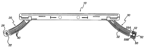
Figure 1 illustrates one embodiment of a headband
of the present invention laid flat with the first end and
the second end thereof disconnected.
Figure 2 illustrates a rear view of the first end
and second end of the headband disconnected from each other.
Figure 3 illustrates a front view of the first end
and the second end of the headband disconnected from each
other.
Figure 4 illustrates the first end and the second
end of the headband in overlapping connection.
Figure 5 illustrates a front, cross-sectional view
of one flange of the fastener seated in one slot of the
first end.
Figure 6 illustrates a front, cross-sectional view
of compression of the fastener of Figure 5 to cause bowing
~ ~
CA 02280851 1999-08-12
WO 98/46096 PCTNS98/04726
of a surface thereof to unseat the flanges thereof from the
slots of the first end to enable relative sliding of the
fastener and the first end.
Figure 7 illustrates a side, cross-sectional view
5 of the seating of two flanges of the fastener in two slots
of the first end.
Figure 8 illustrates a front, cross-sectional view
of another embodiment of a fastener of the present
invention.
Figure 9 illustrates a front, cross-sectional view
of compression of the fastener of Figure 9 to cause bowing
of a surface thereof to unseat the flanges thereof from the
slots of the first end to enable relative sliding of the
fastener and the first end.
Detailed Description of the Invention
Band 10 is a flexible member that may be molded
from an integral piece of a suitable polymeric material to
extend around the head of the user. First end 20 and second
end 30 preferably overlap at the back of the head. Band 10
may be straight from end to end, in which case first end 20
and second end 30 will overlap on the head of the user.
First end 20 and second end 30 may, on the other hand,
extend downward in the rear portion of band 10 across the
nape of the neck. This embodiment is illustrated in
Figure 1. Regardless of which type of band 10 is used,
overlapping ends 20 and 30 are connected in the same manner.
CA 02280851 1999-08-12
WO 98/46096 PCT/US98/04726
6
In that regard, first end 20 preferably comprises
a plurality of longitudinally spaced slots 40 as best
illustrated in Figures 2 and 3. Second end 30 preferably
comprises a fastener 50 which cooperates with spaced
slots 40 to form an adjustable overlapping connection
between first end 20 and second end 30. Fastener 50
preferably comprises at least one flange 52 dimensioned to
seat ir.~ and form a locking connection with one of slots 40
to create an overlapping connection between first end 20 and
second end 30. Preferably, a plurality of flanges 52 are
provided to form a locking connection with an equal number
of slots 40. Flanges 52 are thus preferably longitudinally
spaced in the same manner as slots 40.
Second end 30 preferably further comprises a
longitudinally extending guide slot 32 which cooperates
with a guide lug 22 on first end 20 to assist in guiding the
slide of first end 20 and second end 30 relative to each
other. Guide lug 22 preferably comprises a stem portion 24
(see Figure 9) which slides in slot 32 and a head or flange
member 26 which extends above and below slot 32. Flange
member 26 preferably projects far enough above back
surface 28 of first end 20 to permit a finger of the user to
move it along slot 32 to assist in adjusting the fit of
band 10.
Fastener 50 comprises an opening, preferably a
channel 54, through which first end 20 passes to form a
connection with fastener 50. As illustrated in Figure 5,
channel 54 is preferably, generally C-shaped and dimensioned
to allow first end 20 to be slidably retained therein.
Flanges 52 extend from a surface 56 into channel 54 to
engage and be seated in slots 40. Retaining flanges 58A and
58B contact front surface 29 of first end 20 to slidably
retain first end 20 within channel 54 of fastener 50.
~. ~
CA 02280851 1999-08-12
WO 98/4609b PCT/US98/04726
7
As best illustrated in Figure 7, flanges 52
preferably comprise a first surface 53A which is generally
perpendicular to rear surface 28 of first end 20 and
parallel to the orientation of slots 40 through first
end 20. Flanges 52 also preferably comprise a second
surface 53B that is curved or beveled. First surface 53A
preferably faces the direction that fastener 50 must be slid
to loosen the fit of band 10 (that is, that direction which
decreases the amount of overlap between first end 20 and
second end 30), while beveled or curved surface 53B faces
the direction that fastener 50 must be slid to tighten the
fit of band 10. Consequently, the projection of first
surface 53A of flanges 52 into slots 40 provides substantial
resistance to loosening of band 10, but beveled or curved
second surfaces 53B allows fastener 50 to be relatively
easily slid in the direction required to tighten the fit of
band 10 on the head of the user.
Assuming band 10 is expanded to its largest
circumference, which means that guide lug 22 is at or near
the end of guide slot 32, band 10 is placed on the head of
the user. The user then grips the top and bottom of
fastener 50 with one hand and slides fastener 50 along first
end 20( see Figure 1) as the user pulls guide lug 22 along
second end 30 with the user's other hand. First end 20 and
second end 30 are thereby slid relative to each other to
increase the overlap therebetween until a desirable fit is
obtained. The seating of flanges 52 in slots 40 as
described above substantially prevents undesirable loosening
of band 10 when in this position. This enables the band 10
to be adjusted without removing the helmet from the user's
head.
To loosen or enlarge band 10 for any reason,
fastener 50 is pinched or compressed latitudinally or
CA 02280851 1999-08-12
WO 98/46096 PCT/US98/04726
8
vertically (that is, in the direction of arrows 60
illustrated in Figures 2 and 4), which causes surface 56 to
bow away from back surface 28 of first end 20. As better
illustrated in Figure 6, fastener 50 is dimensioned such
that when it is compressed surface 56 bows sufficiently that
flanges 52 are withdrawn from their seating in slots 40.
Upon such bowing of fastener surface 56, band 10 can be
expanded, for example, by pushing lug guide 22 to the right
and/or by pulling first end 20 to the right, which will move
freely through temporarily deformed fastener 50. When the
compressive force is removed from fastener 50, surface 56
will flatten and flanges 52 will seat in slots 40 to prevent
further enlargement of the circumference of band 10.
To facilitate the bowing of surface 56 and allow
enlargement of band 10 during the compression of
fastener 50, second end 30 is preferably provided with at
least one inwardly extending notch 70. Preferably, two
notches 70 and 72 are provided which extend latitudinally
inward (toward the center of second end 30). One notch 70
preferably extends downward from the top of second end 20,
and another notch 72 preferably extends upward from the
bottom of second end 20. Notches 70 and 72 are preferably
located opposite each other and adjacent fastener 50. The
present inventors have discovered that placing notches 70
and 72 adjacent fastener 50 essentially isolates fastener 50
from the remainder of band 10 during the compression of
fastener 50 and increases the bowing of surface 56 to unseat
flanges 52 and enlarge the circumference of band 10. Absent
notches 70 and 72, the user would have to compress a
substantial portion of band 10 to bow surface 56
sufficiently to unseat flanges 52. Notches 70 and 72 are
preferably positioned as closely to fastener 50 as possible
to minimize that portion of band 10 that is compressed.
CA 02280851 1999-08-12
WO 98/4609b PCT/IJS98/04'726
9
Moreover, to effectively isolate fastener 50 from
the remainder of second end 30 and thus band 10, notches 70
and 72 preferably extend inwardly (that is, toward the
center of second end 30) a sufficient distance such that
substantially no compression of second end 30 on the side of
notches 70 and 72 opposite the location of fastener 50 is
required to unseat flanges 52 from slots 40. In the
embodiment illustrated in Figures 3 and 5, fastener 50
further comprises at least one plastic hinge 59A which
facilitates bowing of surface 56. Preferably, two
hinges 59A and 59B are provided. Hinges 59A and 59B may be
simply formed as longitudinally extending notches in
surface 56 to facilitate bowing. In this embodiment,
notch 70 preferably extends inwardly past hinge 59A, while
notch 72 preferably extends inwardly beyond hinge 59B.
In another embodiment illustrated in Figures 8 and
9, facilitation of bowing can be accomplished without the
use of plastic hinges by providing a fastener 150 comprising
flanges 152 extending from an arched surface 156.
Surface 156 arches away from back surface 28 of first
end 20. The arching of surface 156 away from back
surface 28 of first end 20 facilitates the unseating of
flanges 152 from slots 40 upon application of a compressive
force to fastener 150 as described above (see Figure 9).
Although the present invention has been described
in detail in connection with the above examples, it is to be
understood that such detail is solely for that purpose and
that variations can be made by those skilled in the art
without departing from the spirit of the invention except as
it may be limited by the following claims.