Language selection

Search

Patent 2281074 Summary

Third-party information liability

Some of the information on this Web page has been provided by external sources. The Government of Canada is not responsible for the accuracy, reliability or currency of the information supplied by external sources. Users wishing to rely upon this information should consult directly with the source of the information. Content provided by external sources is not subject to official languages, privacy and accessibility requirements.

Claims and Abstract availability

Any discrepancies in the text and image of the Claims and Abstract are due to differing posting times. Text of the Claims and Abstract are posted:

  • At the time the application is open to public inspection;
  • At the time of issue of the patent (grant).
(12) Patent: (11) CA 2281074
(54) English Title: SOUND ENHANCING BURNER ENCLOSURE FOR FURNACE
(54) French Title: ENCEINTE ANTISONIQUE POUR BRULEUR DE FOUR
Status: Expired and beyond the Period of Reversal
Bibliographic Data
(51) International Patent Classification (IPC):
  • F23M 9/02 (2006.01)
  • F23D 14/46 (2006.01)
  • F23L 1/00 (2006.01)
(72) Inventors :
  • CABRERA, ROBERT E. (United States of America)
  • HILL, TERRY E. (United States of America)
(73) Owners :
  • INTERNATIONAL COMFORT PRODUCTS CORPORATION (USA)
(71) Applicants :
  • INTERNATIONAL COMFORT PRODUCTS CORPORATION (USA) (United States of America)
(74) Agent: NORTON ROSE FULBRIGHT CANADA LLP/S.E.N.C.R.L., S.R.L.
(74) Associate agent:
(45) Issued: 2004-05-11
(22) Filed Date: 1999-08-24
(41) Open to Public Inspection: 2000-02-29
Examination requested: 1999-08-24
Availability of licence: N/A
Dedicated to the Public: N/A
(25) Language of filing: English

Patent Cooperation Treaty (PCT): No

(30) Application Priority Data:
Application No. Country/Territory Date
09/144,378 (United States of America) 1998-08-31

Abstracts

English Abstract


An enclosure surrounding the burner of a furnace, including a top panel, a
rear panel,
a bottom panel, a front panel, and first and second side panels. An air inlet
is provided in one
of the panels. A baffle is provided within the enclosure and extends between
two opposed
panels, each of the opposed panels adjacent the panel having the inlet. A
chamber is partly
defined by the baffle, the inlet opening into the chamber. The chamber is
provided with a
vent through which the inlet is in fluid communication with the burner.


Claims

Note: Claims are shown in the official language in which they were submitted.

THE EMBODIMENTS OF THE INVENTION IN WHICH AN EXCLUSIVE
PROPERTY OR PRIVILEGE IS CLAIMED ARE DEFINED AS FOLLOWS:
1. An enclosure surrounding the burner of a furnace, comprising:
a plurality of contiguous panels defining are enclosed space in which the
burner
is located;
an air inlet to said enclosed space in a first one of said panels; and
an air baffle located within said enclcosed space and having an edge which is
spaced from said first panel, a gap defined by said edge and said first panel,
said air
baffle extending between second and third said panels, said second and third
panels
located on opposite sides of said enclosed space, each of said second and
third panels
adjacent said first panel, said air baffle partly defining a chamber within
said enclosed
space;
wherein said air inlet opens into said chamber, said chamber is provided with
a
vent defined by said gap through which air exits said chamber, and said air
inlet is in
fluid communication with the burner through said vent, the transmission of
noise
emanating from said enclosed space through said air inlet being reduced by
said baffle.
2. The enclosure of claim 1, wherein said air baffle comprises a first leg and
a second leg, said first leg generally parallel to said first panel, said
second leg having
said edge.
3. The enclosure of claim 1, wherein said air baffle is attached to a fourth
said panel, said fourth panel being adjacent each of sari first, second and
third panels.
4. The enclosure of claim 1, wherein said air baffle is attached to said
second and third panels.

5. The enclosure of claim 1, wherein said air baffle is elongate.
6. The enclosure of claim 5, wherein said air inlet is elongate.
7. The enclosure of claim 1, wherein one of said panels and said air baffle
comprises sheet metal having a 22 gauge thickness.
8. The enclosure of claim 1. wherein one of said panels is multi-sided.
9. The enclosure of claim 1, wherein fourth and fifth said panels are
generally mutually perpendicular and are furnace cabinet panels, and said
enclosure
comprises a subassembly comprised of said first, second and third panels, said
subassembly attached to the furnace cabinet panels.
10. The enclosure of claim 9, wherein one of said fourth and fifth panels has
an aperture through which said enclosed space and a heat exchanger are in
fluid
communication.

Description

Note: Descriptions are shown in the official language in which they were submitted.


CA 02281074 1999-08-24
Robert E. Cabrera
Terry E. Hill
SOUND ENHANCING BURNER ENCLOSURE FOR FURNACE
BACKGROUND OF THE INVENTION
The present invention relates to burner enclosures, particularly burner
enclosures for
furnaces.
Burners of the type used in furnaces produce noises associated with the
combustion of
fuel within the furnace. Enclosure of the burners may help attenuate the
transmission of these
noises, but airborne sound emanating from within the enclosure may travel
outward through
the air inlet of such an enclosure. Further, sound transmission may occur
through the walls of
the enclosure. A means of reducing the transmission of noises emanating from
within a
furnace burner enclosure is desirable.
SUMMARY OF THE INVENTION
The present invention provides a sound enhancing enclosure far the burner of a
furnace. The enclosure includes a top panel, a rear panel, a bottom panel, a
front panel, and
first and second side panels. An air inlet is provided in one of the panels. A
baffle is
provided within the enclosure and extends between two opposed panels, each of
the opposed
panels adjacent the panel which includes the inlet. A chamber is partly
defined by the baffle
and the inlet opening into the chamber. The chamber is provided with a vent
through which
the inlet is in fluid communication with the burner.
Further, the sheet metal material from which the enclosure is formed is of a
thickness
which provides sufficient mass to substantially attenuate the transmission of
combustion-
related noises therethrough.
BRIEF DESCRIPTION OF THE DRAWINGS
The above-mentioned and other features and advantages of this invention, and
the
manner of attaining them, will become more apparent and the invention will be
better
understood by reference to the following description of an embodiment of the
invention taken
in conjunction with the accompanying drawings, wherein:
Figure 1 is an upper rear perspective view of a partially assembled furnace
cabinet,
showing an embodiment of a burner enclosure according to the present
invention;
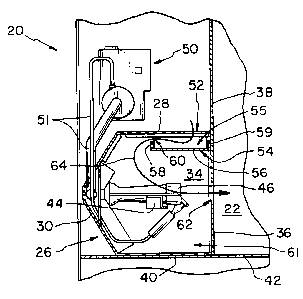
Figure 2 is a fragmentary, sectional side view along line 2-2 of Figure 1;

CA 02281074 1999-08-24
Figure 3 is a fragmentary top view of the cabinet of Figure 1 in which a
portion of the
burner enclosure has been broken away;
Figure 4 is a fragmentary rear view of the cabinet of Figure 1;
Figure 5 is an upper rear perspective view of the enclosure embodiment shown
in
Figure 1;
Figure 6 is a sectional side view along line 6-6 of Figure 5; and
Figure 7 is an upper front perspective view of the enclosure embodiment shown
in
Figure 1.
Corresponding reference characters indicate corresponding parts throughout the
several views. Although the drawings represent an embodiment of the present
invention, the
drawings are not necessarily to scale and certain features may be exaggerated
in order to
better illustrate and explain the present invention. The exemplification set
out herein
illustrate an embodiment of the invention, and such exemplification is not to
be construed as
being exhaustive or to limit the scope of the invention in any manner.
DETAILED DESCRIPTION OF THE INVENTION
Figure 1 shows partially assembled furnace cabinet 20 which includes an
embodiment
of a burner enclosure according to the present invention. Cabinet 20 comprises
heat
exchanger 22 for transferring heat from the combustion gases generated by the
burners of the
furnace to conditioned air forced through heat exchanger 22 by blower assembly
24. The
outlet 25 of blower 24 is directed upwardly as shown in Figure 1. Cabinet 24
further
comprises sound enhancing burner enclosure 26. Enclosure 26 comprises top
panel 28; rear
panel 30, which in the shown embodiment is multi-sided, having a plurality of
angled flat
surfaces; and first and second side panels 32, 34, respectively, which are
located on opposite
sides of enclosure 26. Enclosure 26 further comprises front panel 36, which is
part of
vertical heat exchanger vertical wall 38; and bottom panel 40, which is part
of horizontal
cabinet wall 42. Each side of enclosure 26 may be formed from 22 gauge (0.86
mm, 0.0336
inch thick) aluminized steel, a thickness which provides sufficient mass to
attenuate
combustion-related noise emanating from inside the burner enclosure.
Horizontal cabinet
wall 42, comprising bottom panel 40, may alternatively be formed from
prepainted,
galvanized steel. Further, top panel 28, rear panel 30 and side panels 32, 34
may be formed
2

CA 02281074 1999-08-24
from a single sheet of steel and configured on a brake into the shape shown,
the free edges of
these panels attached together with screws or by means of spot welding.
Disposed within enclosure 26, attached to and extending between first and
second side
panels 32, 34, is burner support bracket 44. Panels 32, 34 are each provided
with centrally
located slotted relief 45 into which tabs (not shown) at opposite ends of
bracket 44 are
received for attachment of bracket 44 to enclosure 26. Attached to bracket 44
are individual
burners 46, 47, 48 and 49, which may vary in number between two and six, based
on the size
and capacity of the furnace; four are shown in the illustrated embodiment. In
the shown
embodiment, the burners are gas fired and, for pilot and normal heating
operation, are
supplied with fuel by means of gas valve mechanism 50, its attendant gas lines
51. Notably,
the portion of the enclosure comprising top panel 28, rear panel 30 and first
and second side
panels 32, 34 may be formed separately and, with gas valve mechanism 50 and
gas lines 51,
bracket 44, and burners 46-49 may be installed into cabinet 20 as a sub-
assembly. Side
panels 32, 34 are provided with inwardly directed flanges 43 (Figure 7) which
lie along
vertical wall 38 and are attached thereto by means of sheet metal screws (not
shown)
engaging holes provided therefor. The enclosure sub-assembly rests upon
horizontal wall 42
but is not attached thereto. Thus, burners 46-49 are enclosed by enclosure 26.
Referring now to Figure 3, the length between panel walls 32, 34 is shown as
dimension L', which ranges between approximately 275 mm and 500 mm, depending
on the
number of burners within the enclosure. Top panel 28 of enclosure 26 is
provided with
elongate air inlet 52 centered between side panels 32, 34 and having length L,
which extends
nearly the entire distance L', and width W of approximately %2 inch (13 mm).
Air inlet 52 is
located proximal vertical wall 38.
Referring to Figures 2, 3 and 6, enclosure 26 is provided with baffle 54 which
is
generally U-shaped in cross-section, having an approximately horizontal center
portion 56
which extends between vertical legs 58, 59. Baffle 54, like the burner
enclosure, may be
formed from 20 gauge aluminized steel. Frontmost baffle leg 59 is located
adjacent vertical
wall 38. Baffle center portion 56 has width W' of approximately 1'/2 inches
(Figure 3); the
length of each vertical leg 58, 59 is approximately'/z inch. Baffle center
portion 56 is located
directly below inlet 52, at a distance D' (Figure 6) of approximately one
inch. Baffle 54
extends between and is attached to side panels 32, 34 and, with the side
panels, top panel 28,

CA 02281074 1999-08-24
and a portion of front panel 36, defines muffler chamber 55, which is best
envisioned with
reference to Figures 2 and 6. The free edge of rearmost vertical baffle leg 58
is disposed
distance A below the lower surface of top panel 28, forming elongate vent 60
which extends
the entire interior width of enclosure 26 and through which air exits muffler
chamber 55. Air
which supports combustion at the burners is thus introduced to enclosure 26
through inlet 52,
and flows through chamber 55 and vent 60 before reaching main burner enclosure
chamber
61. The gaseous combustion products exit chamber 61 through apertures 62
provided in
vertical wall 38, entering heat exchanger 22. Baffle 54 serves as a barrier
against airborne
noise emanating from inside the burner enclosure, preventing its transmission
from main
burner chamber 61 to inlet 52.
The flow of combustion air and combustion products is represented by arrow 64
in
Figure 2, which shows air entering inlet 52, flowing through chamber 55 and
vent 60,
flowing through main enclosure chamber 61, and entering heat exchanger 22 as
products of
combustion through apertures 62. Referring to Figure l, combustion gases are
exhausted
from heat exchanger 22 through exhaust fan assembly 68. The heated conditioned
interior air
exits cabinet assembly 20 in the direction of arrow 70, from which it is
ducted through a
system of ventilation ducts to a building to be heated.
While this invention has been described as having a preferred design, the
present
invention may be further modified within the spirit and scope of this
disclosure. This
application is therefore intended to cover any variations, uses or adaptations
of the invention
using its general principles. Further, this application is intended to cover
such departures
form the present invention as come within known or customary practice in the
art to which
this invention pertains.
4

Representative Drawing
A single figure which represents the drawing illustrating the invention.
Administrative Status

2024-08-01:As part of the Next Generation Patents (NGP) transition, the Canadian Patents Database (CPD) now contains a more detailed Event History, which replicates the Event Log of our new back-office solution.

Please note that "Inactive:" events refers to events no longer in use in our new back-office solution.

For a clearer understanding of the status of the application/patent presented on this page, the site Disclaimer , as well as the definitions for Patent , Event History , Maintenance Fee  and Payment History  should be consulted.

Event History

Description Date
Time Limit for Reversal Expired 2009-08-24
Letter Sent 2008-08-25
Inactive: IPC from MCD 2006-03-12
Grant by Issuance 2004-05-11
Inactive: Cover page published 2004-05-10
Pre-grant 2004-02-24
Inactive: Final fee received 2004-02-24
Letter Sent 2003-09-17
Notice of Allowance is Issued 2003-09-17
Inactive: Approved for allowance (AFA) 2003-08-29
Amendment Received - Voluntary Amendment 2003-05-21
Inactive: S.30(2) Rules - Examiner requisition 2002-12-04
Revocation of Agent Requirements Determined Compliant 2002-06-12
Appointment of Agent Requirements Determined Compliant 2002-06-12
Revocation of Agent Request 2002-04-25
Appointment of Agent Request 2002-04-25
Application Published (Open to Public Inspection) 2000-02-29
Inactive: Cover page published 2000-02-28
Inactive: First IPC assigned 1999-10-08
Inactive: IPC assigned 1999-10-08
Inactive: Filing certificate - RFE (English) 1999-09-23
Filing Requirements Determined Compliant 1999-09-23
Letter Sent 1999-09-23
Application Received - Regular National 1999-09-20
Request for Examination Requirements Determined Compliant 1999-08-24
All Requirements for Examination Determined Compliant 1999-08-24

Abandonment History

There is no abandonment history.

Maintenance Fee

The last payment was received on 2003-07-23

Note : If the full payment has not been received on or before the date indicated, a further fee may be required which may be one of the following

  • the reinstatement fee;
  • the late payment fee; or
  • additional fee to reverse deemed expiry.

Please refer to the CIPO Patent Fees web page to see all current fee amounts.

Fee History

Fee Type Anniversary Year Due Date Paid Date
Registration of a document 1999-08-24
Request for examination - standard 1999-08-24
Application fee - standard 1999-08-24
MF (application, 2nd anniv.) - standard 02 2001-08-24 2001-07-25
MF (application, 3rd anniv.) - standard 03 2002-08-26 2002-08-26
MF (application, 4th anniv.) - standard 04 2003-08-25 2003-07-23
Final fee - standard 2004-02-24
MF (patent, 5th anniv.) - standard 2004-08-24 2004-07-26
MF (patent, 6th anniv.) - standard 2005-08-24 2005-07-08
MF (patent, 7th anniv.) - standard 2006-08-24 2006-07-07
MF (patent, 8th anniv.) - standard 2007-08-24 2007-07-04
Owners on Record

Note: Records showing the ownership history in alphabetical order.

Current Owners on Record
INTERNATIONAL COMFORT PRODUCTS CORPORATION (USA)
Past Owners on Record
ROBERT E. CABRERA
TERRY E. HILL
Past Owners that do not appear in the "Owners on Record" listing will appear in other documentation within the application.
Documents

To view selected files, please enter reCAPTCHA code :


To view images, click a link in the Document Description column. To download the documents, select one or more checkboxes in the first column and then click the "Download Selected in PDF format (Zip Archive)" or the "Download Selected as Single PDF" button.

List of published and non-published patent-specific documents on the CPD .

If you have any difficulty accessing content, you can call the Client Service Centre at 1-866-997-1936 or send them an e-mail at CIPO Client Service Centre.


Document
Description 
Date
(yyyy-mm-dd) 
Number of pages   Size of Image (KB) 
Representative drawing 2000-02-09 1 20
Claims 2003-05-21 2 67
Representative drawing 2003-09-04 1 12
Drawings 1999-08-24 4 117
Cover Page 2000-02-09 1 44
Abstract 1999-08-24 1 15
Description 1999-08-24 4 216
Claims 1999-08-24 2 61
Cover Page 2004-04-07 1 39
Courtesy - Certificate of registration (related document(s)) 1999-09-23 1 140
Filing Certificate (English) 1999-09-23 1 175
Reminder of maintenance fee due 2001-04-25 1 111
Commissioner's Notice - Application Found Allowable 2003-09-17 1 160
Maintenance Fee Notice 2008-10-06 1 171
Correspondence 2002-04-25 3 91
Correspondence 2002-06-12 3 73
Correspondence 2004-02-24 1 39