Note : Les descriptions sont présentées dans la langue officielle dans laquelle elles ont été soumises.
CA 02281074 1999-08-24
Robert E. Cabrera
Terry E. Hill
SOUND ENHANCING BURNER ENCLOSURE FOR FURNACE
BACKGROUND OF THE INVENTION
The present invention relates to burner enclosures, particularly burner
enclosures for
furnaces.
Burners of the type used in furnaces produce noises associated with the
combustion of
fuel within the furnace. Enclosure of the burners may help attenuate the
transmission of these
noises, but airborne sound emanating from within the enclosure may travel
outward through
the air inlet of such an enclosure. Further, sound transmission may occur
through the walls of
the enclosure. A means of reducing the transmission of noises emanating from
within a
furnace burner enclosure is desirable.
SUMMARY OF THE INVENTION
The present invention provides a sound enhancing enclosure far the burner of a
furnace. The enclosure includes a top panel, a rear panel, a bottom panel, a
front panel, and
first and second side panels. An air inlet is provided in one of the panels. A
baffle is
provided within the enclosure and extends between two opposed panels, each of
the opposed
panels adjacent the panel which includes the inlet. A chamber is partly
defined by the baffle
and the inlet opening into the chamber. The chamber is provided with a vent
through which
the inlet is in fluid communication with the burner.
Further, the sheet metal material from which the enclosure is formed is of a
thickness
which provides sufficient mass to substantially attenuate the transmission of
combustion-
related noises therethrough.
BRIEF DESCRIPTION OF THE DRAWINGS
The above-mentioned and other features and advantages of this invention, and
the
manner of attaining them, will become more apparent and the invention will be
better
understood by reference to the following description of an embodiment of the
invention taken
in conjunction with the accompanying drawings, wherein:
Figure 1 is an upper rear perspective view of a partially assembled furnace
cabinet,
showing an embodiment of a burner enclosure according to the present
invention;
Figure 2 is a fragmentary, sectional side view along line 2-2 of Figure 1;
CA 02281074 1999-08-24
Figure 3 is a fragmentary top view of the cabinet of Figure 1 in which a
portion of the
burner enclosure has been broken away;
Figure 4 is a fragmentary rear view of the cabinet of Figure 1;
Figure 5 is an upper rear perspective view of the enclosure embodiment shown
in
Figure 1;
Figure 6 is a sectional side view along line 6-6 of Figure 5; and
Figure 7 is an upper front perspective view of the enclosure embodiment shown
in
Figure 1.
Corresponding reference characters indicate corresponding parts throughout the
several views. Although the drawings represent an embodiment of the present
invention, the
drawings are not necessarily to scale and certain features may be exaggerated
in order to
better illustrate and explain the present invention. The exemplification set
out herein
illustrate an embodiment of the invention, and such exemplification is not to
be construed as
being exhaustive or to limit the scope of the invention in any manner.
DETAILED DESCRIPTION OF THE INVENTION
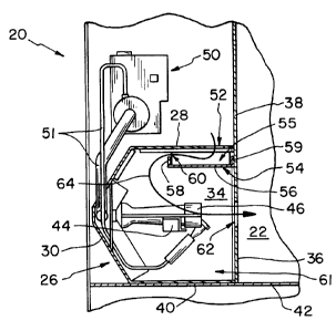
Figure 1 shows partially assembled furnace cabinet 20 which includes an
embodiment
of a burner enclosure according to the present invention. Cabinet 20 comprises
heat
exchanger 22 for transferring heat from the combustion gases generated by the
burners of the
furnace to conditioned air forced through heat exchanger 22 by blower assembly
24. The
outlet 25 of blower 24 is directed upwardly as shown in Figure 1. Cabinet 24
further
comprises sound enhancing burner enclosure 26. Enclosure 26 comprises top
panel 28; rear
panel 30, which in the shown embodiment is multi-sided, having a plurality of
angled flat
surfaces; and first and second side panels 32, 34, respectively, which are
located on opposite
sides of enclosure 26. Enclosure 26 further comprises front panel 36, which is
part of
vertical heat exchanger vertical wall 38; and bottom panel 40, which is part
of horizontal
cabinet wall 42. Each side of enclosure 26 may be formed from 22 gauge (0.86
mm, 0.0336
inch thick) aluminized steel, a thickness which provides sufficient mass to
attenuate
combustion-related noise emanating from inside the burner enclosure.
Horizontal cabinet
wall 42, comprising bottom panel 40, may alternatively be formed from
prepainted,
galvanized steel. Further, top panel 28, rear panel 30 and side panels 32, 34
may be formed
2
CA 02281074 1999-08-24
from a single sheet of steel and configured on a brake into the shape shown,
the free edges of
these panels attached together with screws or by means of spot welding.
Disposed within enclosure 26, attached to and extending between first and
second side
panels 32, 34, is burner support bracket 44. Panels 32, 34 are each provided
with centrally
located slotted relief 45 into which tabs (not shown) at opposite ends of
bracket 44 are
received for attachment of bracket 44 to enclosure 26. Attached to bracket 44
are individual
burners 46, 47, 48 and 49, which may vary in number between two and six, based
on the size
and capacity of the furnace; four are shown in the illustrated embodiment. In
the shown
embodiment, the burners are gas fired and, for pilot and normal heating
operation, are
supplied with fuel by means of gas valve mechanism 50, its attendant gas lines
51. Notably,
the portion of the enclosure comprising top panel 28, rear panel 30 and first
and second side
panels 32, 34 may be formed separately and, with gas valve mechanism 50 and
gas lines 51,
bracket 44, and burners 46-49 may be installed into cabinet 20 as a sub-
assembly. Side
panels 32, 34 are provided with inwardly directed flanges 43 (Figure 7) which
lie along
vertical wall 38 and are attached thereto by means of sheet metal screws (not
shown)
engaging holes provided therefor. The enclosure sub-assembly rests upon
horizontal wall 42
but is not attached thereto. Thus, burners 46-49 are enclosed by enclosure 26.
Referring now to Figure 3, the length between panel walls 32, 34 is shown as
dimension L', which ranges between approximately 275 mm and 500 mm, depending
on the
number of burners within the enclosure. Top panel 28 of enclosure 26 is
provided with
elongate air inlet 52 centered between side panels 32, 34 and having length L,
which extends
nearly the entire distance L', and width W of approximately %2 inch (13 mm).
Air inlet 52 is
located proximal vertical wall 38.
Referring to Figures 2, 3 and 6, enclosure 26 is provided with baffle 54 which
is
generally U-shaped in cross-section, having an approximately horizontal center
portion 56
which extends between vertical legs 58, 59. Baffle 54, like the burner
enclosure, may be
formed from 20 gauge aluminized steel. Frontmost baffle leg 59 is located
adjacent vertical
wall 38. Baffle center portion 56 has width W' of approximately 1'/2 inches
(Figure 3); the
length of each vertical leg 58, 59 is approximately'/z inch. Baffle center
portion 56 is located
directly below inlet 52, at a distance D' (Figure 6) of approximately one
inch. Baffle 54
extends between and is attached to side panels 32, 34 and, with the side
panels, top panel 28,
CA 02281074 1999-08-24
and a portion of front panel 36, defines muffler chamber 55, which is best
envisioned with
reference to Figures 2 and 6. The free edge of rearmost vertical baffle leg 58
is disposed
distance A below the lower surface of top panel 28, forming elongate vent 60
which extends
the entire interior width of enclosure 26 and through which air exits muffler
chamber 55. Air
which supports combustion at the burners is thus introduced to enclosure 26
through inlet 52,
and flows through chamber 55 and vent 60 before reaching main burner enclosure
chamber
61. The gaseous combustion products exit chamber 61 through apertures 62
provided in
vertical wall 38, entering heat exchanger 22. Baffle 54 serves as a barrier
against airborne
noise emanating from inside the burner enclosure, preventing its transmission
from main
burner chamber 61 to inlet 52.
The flow of combustion air and combustion products is represented by arrow 64
in
Figure 2, which shows air entering inlet 52, flowing through chamber 55 and
vent 60,
flowing through main enclosure chamber 61, and entering heat exchanger 22 as
products of
combustion through apertures 62. Referring to Figure l, combustion gases are
exhausted
from heat exchanger 22 through exhaust fan assembly 68. The heated conditioned
interior air
exits cabinet assembly 20 in the direction of arrow 70, from which it is
ducted through a
system of ventilation ducts to a building to be heated.
While this invention has been described as having a preferred design, the
present
invention may be further modified within the spirit and scope of this
disclosure. This
application is therefore intended to cover any variations, uses or adaptations
of the invention
using its general principles. Further, this application is intended to cover
such departures
form the present invention as come within known or customary practice in the
art to which
this invention pertains.
4