Note: Descriptions are shown in the official language in which they were submitted.
CA 02281233 1999-08-31
A,
AX/098
APPARATUS AND METHODS FOR HOLDING A WIRE
IN AN ARMATURF~ WINDING MACHINE
This application claims the benefit of U.S.
Provisional application No. 60/101,352, filed September
22, 1998.
Background of the Inventi0ll
The present application relates to apparatus
and methods for handling ware leads in a machine for
winding components of dynamo-electric machines, such as
armatures or stators of electric motors.
Typical prior art. armature winders are
described in commonly-assigned U.S. Patent x,127,594 to
Lombardi et al., U.S. Patent 5,257,745 to Lombardi et
al., and Stratico U.S. Patent Application No.
09/323,304, filed June l, 1999, each of which is
incorporated by reference in its entirety herein.
Wire grippers have been employed in the prior
art winders to grasp and hold the wires, which have
been delivered from two flyer arms. A typical prior
art wire gripper is described in U.S. Patent 3,927,843
to Dammar, which is incorpc>rated by reference in its
entirety herein. Wire gri.ppers typically grasp and
hold the wires at the completion of winding of the
CA 02281233 1999-08-31
- 2 -
armature. More particularly, at this stage of
manufacture, the flyers of: the winder have
substantially finished winding the coils to the
armature. Subsequently, t:he final leads are
"terminated," or attached, to the commutator, typically
by wrapping around a tang of the commutator. After
termination, each of the t:wo wires extends from the
commutator to the respective flyer. According to this
procedure, each wire gripper grasps a respective wire
at a point between the co~r;mutator and the flyer, and
nearer to the commutator. Each wire gripper holds the
respective wire which it has grasped so that the wire
does not run out of the gripping portion.
A first shearing step may occur wherein each
of the wire grippers, holding a respective wire, moves
to a distant location spaced apart from the armature.
For winders winding thin wires, the grippers pull the
wire in order to shear it against an edge of the
commutator during this movement (e.g., the edge of a
tang where the wire has been previously terminated), or
against specialized cutting apparatus provided on the
armature holding apparatus. For winders winding
thicker wire, i.e., wires which cannot be sheared by
the pull of the grippers, cutters are present to shear
a respective wire between the commutator and the
gripper, once the gripper lzas moved to its distant'
position to add tension to the wire.
The end result, after the first shearing
step, is that each wire is being held at one end by a
wire gripper, and the other end extends to its
respective flyer. According to this apparatus and
procedure, the completely wound armature has been freed
CA 02281233 1999-08-31
3 -
from the wires, and can be unloaded from the winder.
This armature is replaced on the winding machine by a
new armature that needs tc> be wound.
Once the new armature has been positioned
between the flyers, in it~~ position for winding, a next
step is for the wires extending between the wire
grippers and the flyers to become terminated to start
points on the commutator (e. g., first tangs). This
process of termination occurs by rotating the flyer
into position and the use of well-known tooling present
in the winder. After termination, a portion of the
wire extends between the commutator and the flyer to
commence winding, and another portion of the wire
extends between the start points of the commutator and
the wire grippers.
During a second shearing step, the portion of
wire extending between the commutator and the wire
grippers becomes sheared between the start points of
the commutator and the gri:ppers, very near to the start
points of the commutator, either by pulling the wires
or by using cutters, as described above. After cutting
the waste portions, winding the armature may begin.
The gripp,ers are consequently in a condition in which
they are holding respective waste portions of wire.
Waste portions of wire havE~ been created by the two
shearing operations described in the foregoing to free
the wound armature and to allow the new armature to be
wound. Waste portions, held by the grippers, must be
removed from the grippers and placed in a waste bin,
without impeding the winding operations.
The typical prior- art wire gripping apparatus
has a limited range of motion for shearing the wire and
CA 02281233 1999-08-31
4 -
for disposing of waste portions of the wire after
shearing. Moreover, in order to perform the shearing
process, the prior art wire gripping apparatus requires
particular coordination of movement with an armature
shielding and supporting apparatus, and may require the
armature shielding and supporting apparatus to provide
specific cutting devices.
It is therefore an advantage of the present
invention to provide an effective wire gripping
apparatus for grasping and disposing of wire.
It is also an advantage of the present
invention to provide a wire gripping apparatus having a
wide range of motion for operating with armatures of
different sizes and a vari~=_ty of armature gripping and
shielding apparatus.
Summary of the Invention
In accordance wii=h the invention, there is
provided a machine for winding dynamo-electric machine
components, such as an dynamo-electric core. The
winding machine may include machine components, e.g.,
apparatus for supporting a dynamo-electric core and for
dispensing and winding a wire coil about the dynamo-
electric core. The novel apparatus provides a wire
holding assembly movably mounted to the winding
machine. The assembly includes a gripping portion for
releasably holding a portion of a wire. By selectively
moving the wire holding assembly with respect to the
winding machine, the gripping portion may be moved to a
plurality of positions.
In a preferred embodiment, the wire holding
assembly may be selectively, rotatably movable about an
CA 02281233 1999-08-31
- 5 -
axis of the dynamo-electric core held by the apparatus
for holding. The apparatus may also be programmably
and selectively rotatable in order to position the wire
holding assembly in a selected angular position.
Moreover, wire holding assembly may be selectively
moved along the axis of the dynamo-electric core, such
that the gripping portion is relatively movable with
respect to the dynamo-electric core, and with respect
to the apparatus for winding the wire about the dynamo-
electric core.
In accordance with the principles of this
invention, the selective rotation of the wire holding
assembly permits positioning of the gripping assembly
to grasp and hold to a wire in a specified location.
For example, when the wire is installed between a tang
of the commutator and the apparatus for dispensing wire
and wrapping the wire around the dynamo-electric core,
the wire holding assembly may be selectively rotated to
angularly position the gripping portion with respect to
the wire portion. The wire holding assembly may also
be selectively moved to position the gripping portion
to grasp a free end portion of a wire, resulting from a
breakage of the wire typically extending between the
terminal of the dynamo-electric core and the winding
apparatus.
Moreover, the wire holding assembly may be
driven into position that allows access for removing or
mounting one or more additional machine components,
such as, e.g., armature sh:fielding and supporting
apparatus, in accordance with the invention. Further
in accordance with the invention, the selective
rotation of the wire holding assembly permits
CA 02281233 1999-08-31
-- 6 -
positioning of the gripping portion with respect to a
receptacle in order to release severed portions of the
wire into the receptacle.
Brief Description of the Drawings
The above and other objects of the invention
will be apparent upon consideration of the following
detailed description, taken in conjunction with the
accompanying drawings in which:
FIG. 1 is a side elevation view of an
apparatus in accordance with the invention.
FIG. 1 (a) is a 'view in partial section taken
from line la-la of FIG. 1,, of a portion of the
apparatus in accordance wii~h the invention.
FIG. 2 is an elfwational end view from line
2-2 of FIG. 1 in accordance with the invention,
wherein the armature has bE~en omitted from the FIG.
FIG. 3 is a perspective view of the apparatus
of FIG. 1, in accordance with the invention.
FIG. 4 is an elevational view from direction
4 of FIG. 2, with a partial sectional view taken
through line 4'-4', in accordance with the invention.
FIG. 5 is an elevational end view similar to
the view of FIG. 2, illustrating the apparatus in a
different position and additional apparatus in
accordance with the invention.
FIG. 6 is an elevational view taken from the
direction of FIG. 1, illustrating the mounting of the
apparatus of FIG. 1 with respect to armature winding
apparatus, in accordance with the invention.
FIG. 6(a) is an enlarged sectional view taken
along line 6'-6' of FIG. 2.
CA 02281233 1999-08-31
._
FIG. 7 is an enlarged elevational end view,
illustrating the position of the wire in relation to
the armature and the winder, in accordance with the
invention.
FIG. 8 is a view similar to FIG. 7,
illustrating the wire and the winder in a different
position with respect to the armature.
Detailed Description of the Preferred Embodiments
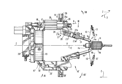
FIG. 1 illustrates a wire holding assembly 10
for a flyer winder machine in accordance with the
invention. The flyer winder machine may include other
machine components, such as armature winding and
shielding assembly, such as that described in U.S.
application 09/323,304, in~~orporated by reference,
above. As illustrated in EIG. 1, the armature 11 is
shown aligned with main axis 12 of the winder. The
wire holding assembly 10, as will be described in
greater detail below, may be mounted to a flyer winder
machine for selective rotai=Tonal movement about the
armature, and, more particularly, about axis 12. The
description of the invention will refer to an armature
for convenience; however, it is understood that any
dynamo-electric core, such as a brushless stator, may
be used with the invention as described. This position
of the armature is advantageous for the processes of
winding and termination of the wire coils by the
winder. For sake of clarity, in FIG. 1 flyer arms 13
and 13', which dispense the wire to the armature and
wind the wire about the armature, have been shown in
partial representation. Again, for the sake of
clarity, devices for holdir.~g the armature and shielding
CA 02281233 1999-08-31
_ g _
the commutator such as those described in U.S.
application 09/323,304, which would typically be
present for winding and termination in areas X and Z,
are not illustrated in FICJ. 1. It is understood that
the device for holding and shielding the armature
described in U.S. applicat:ion 09/323,304 is merely
illustrative, and other devices for serving that
purpose are contemplated for use with the present
invention.
With reference to FIGS. 1-5, and in
particular to FIG. 1, exemplary grippers for grasping
and holding the wires have been referenced with numbers
l4 and 14'. tripper 14 grasps and holds wire 15
leading to flyer 13. Similarly, gripper 14' grasps and
holds wire 15' leading to flyer 13'. Wire 15 has been
terminated to tang lla of a commutator llc, and wire
15' has been terminated to tang llb.
tripper units 16 and 16' are attached to
respective support brackets 17 and 17' respectively,
which in turn are attached, for example, by means of
bolts 18 and 18', respectively, to support ring 19. In
a preferred embodiment, the attachment of these gripper
units 16/16' to the support brackets 17/17' may be
achieved by bolting the rear end of air cylinders 20
and 20', respectively, to support brackets 17 and 17'.
For sake of clarity, constructional and
functional information will be described concerning
gripper unit 16 having gripper 14, only. tripper unit
16' having gripper 14', is substantially identical to
gripper unit 16 in terms of: construction and function,
such that discussion of gri.pper unit 16 generally
applies to gripper unit 16', as well.
CA 02281233 1999-08-31
._ g _
FIG. 1 illustrates grippes unit 16 in a
partial section view. FIG. 1(a) is an enlarged view of
the end portion of grippes 14. As illustrated in FIG.
1(a), grippes 14 includes a cylindrical sheath 21 and
5 rod 22. The forward end of sheath 21 is provided with
a slanted abutment portion. 21a. The forward end of rod
22 is provided with slanted abutment portion 22a.
Abutment portions 21a and 22a confront each other, in a
substantially parallel manner, so that wire 15 can be
held between them.
As illustrated in FIG.1, rod 22 is slidable
within sheath 21. Consequently, the wire 15 may be
pressed between abutment portions 21a and 22a (FIG.
1(a)). A sufficient pressing action by rod 22 will
15 maintain the wire firmly held between portions 21a and
22a. When rod 22, and hence abutment portion 22a, is
retracted in direction D, abutment portion 21a is
exposed to grasp the wire. Once the wire has been
brought against abutment portion 21a, rod 22 is
20 extended oppositely to direction D so that the wire
becomes trapped and held firmly between abutment
portion 21a and 22a as shown in FIG. 1(a). -It is
understood that the grippes 14 configuration described
herein is exemplary, and alternative configurations to
25 grasp the wire are contemplated, e.g., pivotable
grasping fingers or hook configurations.
With continued reference to FIG. 1, the rear
end 22b of rod 22 is enlarged, and provided with seals
so that it may act as a piston in cylinder portion 23a
30 of support arm 23. Support arm 23 is fixed with
respect to axle 24. Axle 24 may have passages for the
supply of pressurised air to either side of the
CA 02281233 1999-08-31
.- 10 -
enlarged portion of rod 2:2, which is within cylinder
portion 23a. The supply of this pressurised air will
move rod 22 in direction 17, or oppositely to direction
D, depending on which side of the enlarged portion
5 supplied. (Fork structure 27 also includes air
cylinder 29. The piston rod of air cylinder 29 can
protrude into fork structure 27.)
Support arm 23 rnay be pivotably supported by
fork structure 27. Fork ;structure 27 may be fixed with
10 respect to the front end of air cylinder 20. More
particularly, axle 24 of support arm 23 may be
supported by sides 27a and 27b of fork structure 27.
This preferred configuration allows support arm 23, and
thus gripper 14, to pivot about axis 28 of axle 24
15 (which extends perpendicu7_arly out of the plane of
FIG. 1). Gear sector 25 is fixed with respect to
support arm 23 and pivotable therewith. Rack 26 is
movable in direction D and oppositely to direction D.
Rack 26 may be bolted to t:he end portion of the piston
20 rod of cylinder 20 and be movable therewith. Gear
sector 25 preferably intermeshes with rack 26. Rack
26 may be guided to move along the inside surface of
fork structure 27.
By moving the piston rod of air cylinder 20,
25 rack 26 advances longitudinally, and rotates gear
sector 25 by intermeshing with gear sector 25.
Consequently, gripper 14 pivots about axis 28 of axle
24 and moves with respect to the armature. More
particularly, movement of cylinder 20 in direction D
30 causes gripper 24 to pivot in direction 30. Similarly,
gripper 14' can be made to pivot in direction 30' by
the use of cylinders 20' and 29'.
CA 02281233 1999-08-31
-- 11 -
tripper 14 is p_ivotable about axis 28 through
a range of motion, including three selected positions
along such range of motion, i.e., 45, 46 and 47.
(Similarly, gripper 14' pivots through a range of
5 motion including positions 45',46', and 47'.) A
forward position may be that in which the grippers 14
and 14' are respectively 7_ocated at positions 45 and
45' (see, FIG. 3). These positions are relatively
close to the armature, and may allow grippers 14 and
10 14' to grasp, respectively, wire 15 extending from
flyer 13, and wire 15' extending from flyer 13', after
termination of tangs lla and llb.
With continued reference to FIG. 1, rack 26
is provided with a raised portion, such as abutment
15 protuberance 26a. The pi:~ton rod of air cylinder 29 is
movable in direction B, and is illustrated out of fork
structure 27. However, abutment protuberance 26a and
the piston rod of air cylinder 29 may engage when the
piston rod of air cylinder 29 protrudes into fork
20 structure 27 and the piston rod of cylinder 20 is
retracted in direction D from its fully extended
position (not shown in the FIG.). As described above,
retraction of the piston rod of cylinder 20 causes
gripper 14 to swing in direction 30. When the rod of
25 piston 29 is extended into fork structure 27,
protuberance 29a will engage the rod of piston 29 and
prevent further movement of gripper 14 in direction 30.
When the travel of grippers 14 and 14' are
stopped in this way, they may be located at
30 intermediate positions 46 and 46' (see, FIG. 3) which
are positions spaced further away from the armature
than positions 45 and 45'.
CA 02281233 1999-08-31
12 -
By retracting the piston rod of air cylinder
29 out of fork structure 27, and further retracting the
piston rod of air cylinder 20, gripper 14 may be
pivoted even further from the armature in direction 30
5 to position 47, for example. Similarly gripper 14' can
be located at position 47' (see, FIG. 3). Movement of
gripper 14 in direction 3f or opposite to direction 30
about axis 28 represents a. degree of freedom in the
range of motion of the present invention with respect
10 to the armature. Similarly, movement of gripper 14' in
direction 30' or opposite direction 30' represents a
degree of freedom.
With reference to FIG. 4, support ring 19 may
be connected to main gear 35 by a flange connection
15 using bolts 36. Support ring 19 and main gear 35 are
supported for angular rotation around main axis 12 of
the winder, by being mounted on ball bearings 36' and
36". These ball bearings may be maintained at a
required distance apart from each other by spacer
20 means, such as spacer ring 37. The bolt connection to
join main gear 35 to support ring 19 pushes the ball
bearings toward each other, while spacer 37 maintains
separation. A drive unit, such as air cylinder 39, is
fixed to casing 41. Pinion gear 38 is fixed to the
25 output shaft of air cylinder 39, and meshes with main
gear 35. Air cylinder 39, when pressurised, causes~its
output shaft to rotate either in one or the other of
two opposite rotation dire~~tions. This causes pinion
gear 38 to rotate as well. As a result of the
30 intermeshing of main gear :35 with rotating pinion gear
38, main gear 35 and support ring 19 will rotate either
in directions 38' and 38" around main axis 12.
CA 02281233 1999-08-31
- 13 -
trippers 14 and 14', which are attached to ring 19,
will also move in direction 38' or 38" with ring 19.
Stop units 42 a.nd 43 are also supported on
casing 41. Support bracket 17 has on its rear end
5 shock absorber 44 with contact pins 44a and 44b that
extend substantially tangentially to the directions 38'
and 38" of rotation. As illustrated in FIG. 2, contact
pin 44a may abut against a rod of stop unit 42 to stop
rotation of support ring 19 (and to absorb the
10 consequential vibrations) when rotation occurs in
direction 38", and contact pin 44b may abut against an
extendable rod of stop unit 43, to stop rotation of
support ring 19 (and to absorb the consequent
vibrations) when rotation occurs in direction 38'.
15 The rotation of support ring 19 about axis 12
provides grippers 14 and 14' with a range of motion in
another direction, i.e., angular motion about the
armature. This range of motion includes at least two
positions, i.e., positions 48 and 49 for gripper 14 and
20 positions 48' and 49' for gripper 14'. When support
ring 19 is stopped by stop unit 42, grippers 14 and 14'
are positioned at positions 48 and 48', respectively,
as shown in FIG. 2. Conversely, when support ring 19
is stopped by stop unit 43, grippers 14 and 14' are
25 positioned at positions 49 and 49', respectively, as
shown in FIG. 5.
The functions of grippers 14 and 14', in the
various positions 45, 46, 47, 48 and 49 (respectively
for gripper 14) and 45', 46', 47', 48' and 49'
30 (respectively for gripper 14') will now be described.
Following termination of the wire to the
final tang lla, gripper 14 may be at position 45 with
CA 02281233 1999-08-31
14 -
respect to a first direction of movement (e. g.,
pivoting movement about axis 28) and at position 48
with respect to a second direction of movement (e. g.,
angular movement about axis 12), and grasps the wire
5 coming from the tang lla and leading to the flyer.
While holding wire 15, gr:ipper 14 moves in one
direction of movement to position 46 further apart from
the armature, while still remaining in position 48.
This causes the wire being held by the gripper to
10 become taut so that it ca:n be sheared near to the tang
by the pull of the gripper or by the cutter. The
degree of tautness necessary to cut the wire may be
determined by one skilled in the art, taking into
account the characteristics of the wire, the cutting
15 surface, and other factors. tripper 14 remains in
position 46 during unloading of a wound armature and
loading of a new armature. Later gripper 14 will
return to position 45 for grasping wire 15 after it has
been terminated to the first tang, such as tang lla, of
20 a new armature. Once the wire has been terminated to
the first tang and has been grasped by gripper 14,
gripper 14 then moves to position 47 (see, FIG. 3), for
shearing and for being at a distant position from the
central area where the flyers accomplish their orbits
25 of rotation.
After this operation, gripper 14 will be
holding in position 47 a waste piece WP of wire
produced by the two shearing operations, described in
the foregoing, to free the wound armature and terminate
30 the new armature on the i:irst tang. tripper 14'
accomplishes, for a tang such as tang llb, similar
operations to those described for gripper 14. The
CA 02281233 1999-08-31
- 15 -
operations for grippers 14 and 14' may occur
simultaneously. At the en.d of these operations,
gripper 14' may also have a waste piece WP when it is
in position 47'. Support ring 19 is then rotated to
selectively bring gripper 14 to position 49, and
gripper 14' to position 49', as shown in FIG. 5. Once
this situation has been reached, gripper 14 may release
waste piece WP so that it passes to a receptacle, such
as collecting bin CB, which may have a conveying
structure, such as chute CH, to direct the waste
portion WP into the collecting bin CB. The receptacle
may be configured such that chute CH is not required
(e.g., collecting bin CB may be wider). tripper 14'
may release the waste piece WP which it is holding when
it is still in position 48', because gripper 14' is
positioned with respect to collecting bin CB, i.e.,
collecting bin CB is directly below.
Bringing grippers 14 into positions 49 and 47
leaves room in area X and along vertical direction V
(see FIGS. 5 and 6) to allow dismounting and reassembly
of the shielding and armature gripping tooling (not
shown in the FIGS.), which may be located in area X.
Tooling useful for this purpose has been described, for
example, in U.S. application 09/323,304. This tooling
may be removed by moving ii. in direction V, to be
dismounted, and opposite to direction V to be
reassembled as has been described in U.S. application
09/323,304.
FIG. 6 shows that: such tooling has been
removed from winder from area X by sliding its
connection portion through groove G, during movement in
direction V. In FIG. 6, gripper unit 16 (illustrated
CA 02281233 1999-08-31
- 16 -
in dashed line) is depicted in an exemplary position
with respect to the tooling to be removed in direction
V. The rotational mounting of wire holding assembly 10
(including gripper unit 16) with respect to unit 9 (the
base portion of the winding machine), allows gripper
unit 16 to be selectively driven to a position or
configuration which provides additional access to allow
removal or mounting of one or many components of the
tooling to unit 9.
The rotational movement of grippers 14 and
14' is selectively controllable to allow grippers 14
and 14' to be rotated to a:ny angular position with
respect to axis 12. For example, air cylinder 39 may
be substituted by an electric motor, which is
controlled to stop for programmable and desired
positions of rotations in directions 38' and 38". This
selective movement may not require the use of stop
units 42 and 43, and shock absorber 44, and allows the
possibility of stopping gr:ippers 14 and 14' at many
angular positions around a:~is 12.
The rotational mounting allows the grippers
to move to predetermined positions around axis 12,
which can also optimize shearing of the wire against a
tang edge by the pulling w~_th the grippers. FIG. 7,
which is a view of tang lla from stack lld of the
armature, shows wire 15 extending to winder 13 that is
to be sheared at point P (against the edge of the tang
lla). With reference to FZ:G. 7 in conjunction with
FIG. l, the longitudinal position of the gripper 14
(and similarly for gripper 14', not shown in FIG. 7) is
between tang lla and lamination stack lld. By rotating
grippers 14 and 14' around axis 12, an ideal angle a
CA 02281233 1999-08-31
_. 17 _
(alpha), formed by the wire being gripped with a
reference axis R, can be formed to shear the wire
correctly along the edge of the tang.
Another application of the rotation of
grippers 14 and 14' around: axis 12 is shown in FIG. 8
for a tang, such as tang lla. As described above for
FIG. 7, the longitudinal position of the gripper is
between the tang lla and the lamination stack lld. For
the case shown in FIG. 8, which is typical of a wide
four pole armature, angle (3 (beta), formed by the wire
going to the flyer and a reference axis R, is very
small due to the large orbit of rotation used by the
flyers. For typical, smaller flyer orbits, i.e., for
larger values of angle ~i (:beta), the gripper would be
in position 48, partially between the wire and tang
lla, to grasp and hold the wire in direction G2.
However, in the case of FIcs. 8, the limited access
between the wire 15 and tang lla may make gripping the
wire 15 in direction G2 di:Eficult. According to the
invention, the gripper may be selectively rotated
around axis 12 to a better position to grasp the wire,
such as direction G1.
Similar principles, which have been described
with reference to FIGS. 7 and 8 for the operations of
gripper 14 in relation to gang lla, apply for gripper
14' in relation to tang llb.
FIG. 6 shows wires holding assembly 10 mounted
on unit 9 of the armature winder. Unit 9 may contain
additional tooling, such as the apparatus described in
U.S. Patent 5,137,221, which is hereby incorporated by
reference herein, and U.S. application 09/323,304,
incorporated by reference above, for actuating the
CA 02281233 1999-08-31
- 18 -
shield tubes and grippers required for positioning and
indexing the armature.
Wire holding assembly 10 (represented in
dotted line) has been mounted on unit 9 by sliding the
inner rings of ball bearing 36' and 36" (not shown in
main view of FIG. 6, because contained within support
ring 19) on a cylindrical collar 51 (see, FIG. 6(a)) of
unit 9. The cylindrical collar extends parallel to
main axis 12. As illustrated in greater detail in FIG.
6(a), radial screws 50, which are screwed into the
cylindrical collar 51, press on spacer 37 to maintain
the bearings fixed in place on the cylindrical collar
51. Apertures 50a are present on support ring 19 to
allow screws 50 to be screwed into cylindrical collar
51. Referencing and final fixing of the gripper
assembly on the cylindrical collar occurs by screwing
screws 54 of casing 41 into an abutment flange 53
extending from the cylindrical collar (FIGS. 4 and 6).
The mounting of wire holding assembly 10 to casing 41
in this manner allows the entire gripping assembly to
be mounted or removed from casing 41 as a unit.
Unit 9 may be movably mounted with respect to
the flyer winders in the direction E by the use of a
track or other mechanism known in the art. The
possibility of placing grippers 14 and 14' in various
angular positions around axis 12, and stopping them in
positions during rotation in direction 30 and 30',
combined within the possibility of selectively moving
unit 9 in direction E, or opposite to direction E (see
FIG. 6) i.e., toward or away from the flyer orbits,
allows the grippers to grasp and hold wires that are
still in condition to leave the flyer, but have become
CA 02281233 1999-08-31
- 19 -
accidentally broken at the armature. A situation like
this is shown in FIG. 5 where the wire WB has been
broken at the armature, which results in a free end
portion G3 at the location. of breakage but is still
supported by flyer 13 at the other end portion. In
FIG. 5, flyer 13 has been rotated to a horizontal
position to present wire WB as shown. tripper 14 can
rotate in direction 38' or 38" about axis 12, pivot in
rotation direction 30 or its opposite direction, and be
shifted longitudinally, by moving unit 9 in direction E
to grasp and hold wire WB adjacent free end portion G3.
Once this has been achieved gripper 14 can be moved
again with any combination of such motions, or their
opposites, to bring wire WB in a predetermined position
to reset the winder after a wire breakage. If
required, gripper 14' can do the same to recover a
broken wire still supported by flyer 13'.
It will be understood that the foregoing is
only illustrative of the principles of the invention,
and that various modifications can be made by thflse
skilled in the art without departing from the scope and
spirit of the invention. :Eor example, it is understood
that the mechanisms illustrated to move the gripper
apparatus in the various directions of movement and
axes of rotation are exemp:Lary, and it is contemplated
that any combination of elE~ctrical motors and hydraulic
pistons under open loop or feedback control may be
utilized to position the gripper assemblies with
respect to the wires and terminal tangs.